HOW TO PROPERLY ORDER PARTS
In addition to part description and part number, please give model number, serial number, and type of gas used.
Page 15
* Requires 2 ** Requires 4 JUNE 2015
REV. 01/2015
NAT. DVCF407C-H DVCF553C-H DVCF557C-H
MODEL NUMBER L.P. DVCF408C-H DVCF554C-H DVCF558C-H
REF. PART LIST PART LIST PART LIST PART LIST
PART DESCRIPTION NO. NO. PRICE NO. PRICE NO. PRICE NO. PRICE
Casing Side, Right 1a 34065 34065 34560 34560
Casing Side, Left 1b 34055 34055 34550 34550
Center Front Panel Assembly 1c 34104 34104 30534 30534
Top Assembly 1d 34050 34050 34050 34050
Upper Back Assembly 1e 34080 34080 34080 34080
Lower Back Assembly 1f 34090 34090 34575 34575
Bottom Assembly 1g 34070 34070 34070 34070
Casing Mounting Brackets N/A *30260 *30260 *30260 *30260
Liner Assembly 2 34115 34115 34600 34600
Fan Shroud Assembly 3 34140 34140 34140 34140
Top Louver 4 34100 34100 34590 34590
Bottom Louver Assembly 6 30100 30100 30100 30100
Upper Front Shield 7 30250 30250 30250 30250
Switch Box 8 30252 30252 30252 30252
Switch Box Cover 9 30253 30253 30253 30253
Lower Front Shield 10 30256 30256 30256 30256
Motor Mounting Bracket 11 *34088 *34088 *34579 *34579
Burner 12 72107 72107 72107 72107
Pilot Bracket 53 34440 34440 34440 34440
Valve, VR8200H-1004, Nat. W/78089 Dis. Bushing 13 78090 N/A 78090 N/A
Valve, VR8200H-1103, L.P. w/78089 Dis. Bushing 13 78091 N/A 78091 N/A
Valve, VR8204H-1006, Nat. w/78089 Dis. Bushing 13b N/A 78092 N/A 78092
Valve, VR8204H-1006 (Conv.), L.P. w/78089 Bushing 13b N/A 78093 N/A 78093
Disappearing Bushing 1/2x3/8 N/A 78089 78089 78089 78089
Manifold 14 72103 72103 72103 72103
Burner Orifice, Natural Gas 15 72147 72147 72140 72140
Burner Orifice, L.P. Gas 15 72149 72149 72141 72141
Fan Motor 16 72108 72108 72110 72110
Fan Blade, Dynacone 17 72111 72111 72111 72111
Rubber Grommet (Requires 4) 18 **78010 **78010 **78010 **78010
Limit Switch 60T11-L220F 19 N/A N/A 72160 72160
Limit Switch 60T11-L180F 19 78065 78065 N/A N/A
Fan Switch 60T12 F110 Degree 20 78064 78064 78064 78064
Aux. Limit Switch 60T15-L350 22 78086 78086 78086 78086
Thermostat 24 Volt 23 78355 78355 78355 78355
Transformer 24 78069 78069 78069 78069
Transformer Plate N/A 34089 34089 34089 34089
Terminal Board 35 78300 78300 78300 78300
Pilot 0.140.512, Natural Gas (w/Electrode) 25 72020 N/A 72020 N/A
Pilot 0.140.502, L.P. Gas (w/Electrode) 25 72021 N/A 72021 N/A
Cozy Handle 26 84003 84003 84003 84003
Thermostat Wire 27 74518 74518 74518 74518
Thermocouple Q309A1954 28 78095 N/A 78095 N/A
Insulated Staples 29 74209 74209 74209 74209
Pilot Assy. Electronic w/Flame Ignitor Nat. 25b/28b N/A 78098 N/A 78098
Pilot Assy. Electronic w/Flame Ignitor L.P. 25b/28b N/A 78099 N/A 78099
Wiring Harness 30 72251 72252 72253 72250
DVCF403C-H
DVCF404C-H
PARTS LIST CONTINUED
Mr. Contractor, we only sell parts through our wholesalers, but the prices listed above are for your convenience. For prompt
parts service, contact the wholesaler from which you purchased your Cozy heater. NOTE: Parts & schematic drawings on
current models are shown at www.cozyheaters.com.
PART
NO.
HOW TO PROPERLY ORDER PARTS
In addition to part description and part number, please give model number, serial number, and type of gas used.
Page 15
* Requires 2 ** Requires 4 JUNE 2015
REV. 01/2015
NAT. DVCF407C-H DVCF553C-H DVCF557C-H
MODEL NUMBER L.P. DVCF408C-H DVCF554C-H DVCF558C-H
REF. PART LIST PART LIST PART LIST PART LIST
PART DESCRIPTION NO. NO. PRICE NO. PRICE NO. PRICE NO. PRICE
Casing Side, Right 1a 34065 34065 34560 34560
Casing Side, Left 1b 34055 34055 34550 34550
Center Front Panel Assembly 1c 34104 34104 30534 30534
Top Assembly 1d 34050 34050 34050 34050
Upper Back Assembly 1e 34080 34080 34080 34080
Lower Back Assembly 1f 34090 34090 34575 34575
Bottom Assembly 1g 34070 34070 34070 34070
Casing Mounting Brackets N/A *30260 *30260 *30260 *30260
Liner Assembly 2 34115 34115 34600 34600
Fan Shroud Assembly 3 34140 34140 34140 34140
Top Louver 4 34100 34100 34590 34590
Bottom Louver Assembly 6 30100 30100 30100 30100
Upper Front Shield 7 30250 30250 30250 30250
Switch Box 8 30252 30252 30252 30252
Switch Box Cover 9 30253 30253 30253 30253
Lower Front Shield 10 30256 30256 30256 30256
Motor Mounting Bracket 11 *34088 *34088 *34579 *34579
Burner 12 72107 72107 72107 72107
Pilot Bracket 53 34440 34440 34440 34440
Valve, VR8200H-1004, Nat. W/78089 Dis. Bushing 13 78090 N/A 78090 N/A
Valve, VR8200H-1103, L.P. w/78089 Dis. Bushing 13 78091 N/A 78091 N/A
Valve, VR8204H-1006, Nat. w/78089 Dis. Bushing 13b N/A 78092 N/A 78092
Valve, VR8204H-1006 (Conv.), L.P. w/78089 Bushing 13b N/A 78093 N/A 78093
Disappearing Bushing 1/2x3/8 N/A 78089 78089 78089 78089
Manifold 14 72103 72103 72103 72103
Burner Orifice, Natural Gas 15 72147 72147 72140 72140
Burner Orifice, L.P. Gas 15 72149 72149 72141 72141
Fan Motor 16 72108 72108 72110 72110
Fan Blade, Dynacone 17 72111 72111 72111 72111
Rubber Grommet (Requires 4) 18 **78010 **78010 **78010 **78010
Limit Switch 60T11-L220F 19 N/A N/A 72160 72160
Limit Switch 60T11-L180F 19 78065 78065 N/A N/A
Fan Switch 60T12 F110 Degree 20 78064 78064 78064 78064
Aux. Limit Switch 60T15-L350 22 78086 78086 78086 78086
Thermostat 24 Volt 23 78355 78355 78355 78355
Transformer 24 78069 78069 78069 78069
Transformer Plate N/A 34089 34089 34089 34089
Terminal Board 35 78300 78300 78300 78300
Pilot 0.140.512, Natural Gas (w/Electrode) 25 72020 N/A 72020 N/A
Pilot 0.140.502, L.P. Gas (w/Electrode) 25 72021 N/A 72021 N/A
Cozy Handle 26 84003 84003 84003 84003
Thermostat Wire 27 74518 74518 74518 74518
Thermocouple Q309A1954 28 78095 N/A 78095 N/A
Insulated Staples 29 74209 74209 74209 74209
Pilot Assy. Electronic w/Flame Ignitor Nat. 25b/28b N/A 78098 N/A 78098
Pilot Assy. Electronic w/Flame Ignitor L.P. 25b/28b N/A 78099 N/A 78099
Wiring Harness 30 72251 72252 72253 72250
DVCF403C-H
DVCF404C-H
PARTS LIST CONTINUED
Mr. Contractor, we only sell parts through our wholesalers, but the prices listed above are for your convenience. For prompt
parts service, contact the wholesaler from which you purchased your Cozy heater. NOTE: Parts & schematic drawings on
current models are shown at www.cozyheaters.com.
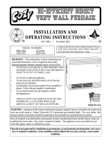
ATTN: CONTRACTORS & TECHNICIANS - We only sell parts through our wholesalers.
For prompt parts service, contact the wholesaler from which you purchased your Cozy heater.
NOTE: Parts and schematic drawings on current models are shown at www.cozyheaters.com
*Requires 2 **Requires 4
HOW TO PROPERLY ORDER PARTS
In addition to part description and part number, please give model number, serial number, and type of gas used.
Page 15
* Requires 2 ** Requires 4 JUNE 2015
REV. 01/2015
NAT. DVCF407C-H DVCF553C-H DVCF557C-H
MODEL NUMBER L.P. DVCF408C-H DVCF554C-H DVCF558C-H
REF. PART LIST PART LIST PART LIST PART LIST
PART DESCRIPTION NO. NO. PRICE NO. PRICE NO. PRICE NO. PRICE
Casing Side, Right 1a 34065 34065 34560 34560
Casing Side, Left 1b 34055 34055 34550 34550
Center Front Panel Assembly 1c 34104 34104 30534 30534
Top Assembly 1d 34050 34050 34050 34050
Upper Back Assembly 1e 34080 34080 34080 34080
Lower Back Assembly 1f 34090 34090 34575 34575
Bottom Assembly 1g 34070 34070 34070 34070
Casing Mounting Brackets N/A *30260 *30260 *30260 *30260
Liner Assembly 2 34115 34115 34600 34600
Fan Shroud Assembly 3 34140 34140 34140 34140
Top Louver 4 34100 34100 34590 34590
Bottom Louver Assembly 6 30100 30100 30100 30100
Upper Front Shield 7 30250 30250 30250 30250
Switch Box 8 30252 30252 30252 30252
Switch Box Cover 9 30253 30253 30253 30253
Lower Front Shield 10 30256 30256 30256 30256
Motor Mounting Bracket 11 *34088 *34088 *34579 *34579
Burner 12 72107 72107 72107 72107
Pilot Bracket 53 34440 34440 34440 34440
Valve, VR8200H-1004, Nat. W/78089 Dis. Bushing 13 78090 N/A 78090 N/A
Valve, VR8200H-1103, L.P. w/78089 Dis. Bushing 13 78091 N/A 78091 N/A
Valve, VR8204H-1006, Nat. w/78089 Dis. Bushing 13b N/A 78092 N/A 78092
Valve, VR8204H-1006 (Conv.), L.P. w/78089 Bushing 13b N/A 78093 N/A 78093
Disappearing Bushing 1/2x3/8 N/A 78089 78089 78089 78089
Manifold 14 72103 72103 72103 72103
Burner Orifice, Natural Gas 15 72147 72147 72140 72140
Burner Orifice, L.P. Gas 15 72149 72149 72141 72141
Fan Motor 16 72108 72108 72110 72110
Fan Blade, Dynacone 17 72111 72111 72111 72111
Rubber Grommet (Requires 4) 18 **78010 **78010 **78010 **78010
Limit Switch 60T11-L220F 19 N/A N/A 72160 72160
Limit Switch 60T11-L180F 19 78065 78065 N/A N/A
Fan Switch 60T12 F110 Degree 20 78064 78064 78064 78064
Aux. Limit Switch 60T15-L350 22 78086 78086 78086 78086
Thermostat 24 Volt 23 78355 78355 78355 78355
Transformer 24 78069 78069 78069 78069
Transformer Plate N/A 34089 34089 34089 34089
Terminal Board 35 78300 78300 78300 78300
Pilot 0.140.512, Natural Gas (w/Electrode) 25 72020 N/A 72020 N/A
Pilot 0.140.502, L.P. Gas (w/Electrode) 25 72021 N/A 72021 N/A
Cozy Handle 26 84003 84003 84003 84003
Thermostat Wire 27 74518 74518 74518 74518
Thermocouple Q309A1954 28 78095 N/A 78095 N/A
Insulated Staples 29 74209 74209 74209 74209
Pilot Assy. Electronic w/Flame Ignitor Nat. 25b/28b N/A 78098 N/A 78098
Pilot Assy. Electronic w/Flame Ignitor L.P. 25b/28b N/A 78099 N/A 78099
Wiring Harness 30 72251 72252 72253 72250
DVCF403C-H
DVCF404C-H
PARTS LIST CONTINUED
Mr. Contractor, we only sell parts through our wholesalers, but the prices listed above are for your convenience. For prompt
parts service, contact the wholesaler from which you purchased your Cozy heater. NOTE: Parts & schematic drawings on
current models are shown at www.cozyheaters.com.