Humminbird TCR 101 Operating instructions

Type
Operating instructions

Humminbird TCR 101: Experience Precision Fishfinding and Depth Measurement

The Humminbird TCR 101 is an advanced fishfinder designed to provide accurate depth readings and detailed fish arches. With its compact size and easy-to-use interface, it's perfect for anglers of all skill levels.

Features:

  • Clear, crisp display with adjustable backlighting for excellent visibility in all conditions
  • Dual-frequency sonar (200/455 kHz) for versatile fishfinding in various water depths
  • Fish ID+ technology for clear identification of fish species and sizes
  • Depth capability up to 600 feet for deep-water fishing
TRANSDUCER MOUNTING PROCEDURE
Humminbird’s high-speed transducer is supplied with your LCR. This transducer has been
designed to give good high speed readings on most all boat designs, including aluminum.
Please carefully consider the following before installing your transducer.
TRANSDUCER MOUNTING OPTIONS
A. Transom Mount- The Humminbird high speed transducer allows the transducer element to be
mounted below the bottom of the boat hull keeping the transducer out of turbulent water and
insuring good high speed operation. The transducer will absorb the blow of any obstruction
by rotating up out of the metal spring bracket without harming the transducer, or your boat.
The transducer can be re-engaged by simply rotating the transducer down and snapping it
back in place. (See Figure A)
B. Inside Hull Mount- The high speed transducer can be mounted inside the hull (without pivot
assembly) using the proper two-part epoxy, such as Humminbird’s epoxy kit. Even though
there is some loss of signal in shooting through the hull, your LCR will perform well with this
type of installation. You cannot shoot through the hull of an aluminum boat.
C. Trolling motor Mount- This type of transducer is not supplied with your LCR. It is designed to
mount on the foot of a trolling motor. You may exchange your un-used high speed
transducer for a trolling motor transducer. Call the Humminbird Customer Service
Department.
D. Bronz Thru-Hull Mount- This transducer is not supplied with your LCR but for an additional
cost you may exchange your un-used high speed transducer for a bronz thru-hull. The bronz
thru-hull transducer has a threaded stem which installs through a hole drilled in the boat hull,
leaving the housing exposed under the boat. This type of installation must be used for many
boats with in-board engines, because there is no suitable location on the transom away from
the noise and turbulence created by the prop. A bronz thru-hull transducer should be installed
by qualified personnel only.
The LCR will operate well at high speeds with a properly mounted transducer. Remember, a
transducer will not work transmitting through air or through air bubbles.
1. TRANSOM MOUNTING PROCEDURE
Step 1.
MOUNTING LOCATION- It is important that the transducer be mounted on the transom where
water flow is in constant contact with the transducer. You may wish to observe the rear of the
boat while it is moving through the water to determine the best mounting location.
Step 2.
BRACKET INSTALLATION (Aluminum Boats)- To install the metal bracket on an aluminum boat
locate the template on the transom between rows of rivets, or ribs that are on the bottom of the
boat. Align the template so that the bottom corner of the template nearest the center of the
transom is on the bottom edge of the transom.
Once the location is determined mark and drill three 7/64” dia.. holes noted on the template.
Attach the metal bracket using three #10 self threading screws supplied. Be sure to align holes in
the center of the
Bracket slots. On some aluminum boats it may be necessary to use a wood back-up plate. It is
important to use a silicone sealant between the screwhead and bracket in order to prevent
leaking. (See Figure C)
Step 2.
BRACKET INSTALLATION (Fiberglass Boats)- If your boat has a stepped transom located
below and under the main transom, the compact transducer design allows mounting in this area.
This mounting location is recommended for good reading at very high speeds. (See Figure D)
To install the metal bracket on a fiberglass boat, locate the template on the transom in the same
manner as for an aluminum boat. (See Figure C)
NOTE: On boats with more than 15 degree deadrise angle it may be necessary to mount the
transducer slightly off parallel with the water level. (See Figure E)
Mark and drill the three 9/64” dia. holes as shown on the template. Attach the metal bracket using
the three #10 self threading screws supplied. Be sure to align the holes so that they are centered
vertically in the three slots found in the bracket. It is important to use a silicone sealant between
the screwhead and bracket in order to prevent leaking.
Step 3.
TRANSDUCER PIVOT ASSEMBLY- Assemble the pivot to the transducer main body using the
two ¼”x5/8” allen head screws, two 3/8” tooth washers and two, ¼” square nuts. Make sure the
tooth washers are sandwiched between the transducer main body and the pivot. The square nuts
are trapped inside the pivot and will not rotate as the allen head screws are tightened.
HOWEVER, DO NOT TIGHTEN AT THIS POINT. (See Figure F)
Step 4
TRANSDUCER ASSEMBLY- Insert the transducer assembly into the metal bracket from the
bottom. Push up until the holes in the plastic pivot align with the uppermost holes in the bracket.
Slide the O-ring on to the headed pin and insert it through the two parts. Assemble by screwing
the ¼”x3/8” allen head screw into the end of the pin and tighten. (See Figure G)
Step 5
ANGLE ALLIGHMENT- Set the transducer angle so that it is parallel with the bottom of the boat
hull. Once proper alignment is achieved, tighten the two allen head screws using the 5/32” allen
wrench provided. The screws are visible through the access holes on each side of the metal
bracket. Check to make sure the transducer main body is rigidly fastened to the pivot. (See
Figure H)
Step 6
CHECK POSITION OF TRANSDUCER- At this point, check to see that the bottom of the
transducer is a minimum of ¼” below the bottom of the transom. (However, as noted in STEP 2,
the top of the transducer cannot fall below the bottom of the transom). If it is not, remove the
transducer assembly from the metal bracket by removing the pin installed during STEP 3. Loosen
the metal bracket mounting screws, re-position the bracket utilizing it’s slotted holes, tighten and
re-assemble. It may be necessary to replace the silicone sealant after this adjustment is made.
NOTE: It may be necessary to make several high speed runs to adjust transducer either
UP/DOWN or to re-adjust the angle to achieve optimum results.
Step 7
CABLE CLAMPS- Install cable clamps as necessary by drilling a 1/8” dia. hole for the # 8 screw
supplied.
2. INSIDE HULL MOUNTING PROCEDURE
Warning: In order to achieve proper results with this type installation, it is important that the
transducer be mounted by someone familiar with the use of two part epoxy adhesives. For this
reason, Techsonic Industries, Inc. will not be responsible for any damage due to the mounting of
your transducer in this manner.
NOTE: An Epoxy Kit (Part N. EPK) is available from Humminbird. This Epoxy Kit has been
formulated for Inside Hull Transducer Installation.
1. Select as flat an area as possible near the aft end and center of boat where the hull is thin
and not double. If the bottom has a runner down the center of boat, select an area to one side
of the runner, but as close to the runner as possible.
2. Clean the inside of the boat with lacquer thinner in the area transducer is to be mounted.
Outside of boat in this area should also be cleaned. (Not with lacquer thinner).
3. Put approximately one inch of water in the bottom of the boat.
4. Put transducer in the water. The bottom of the transducer should be in a flat area and should
be in good contact with the bottom of the boat.
5. Operate the LCR with the boat operating at high speed. The transducer may have to be
moved in order to find an area where satisfactory operation is observed.
6. When an area is found that produces satisfactory operation, mark the location of the
transducer.
7. Remove the water and transducer and clean the marked area and the bottom of the
transducer thoroughly.
8. Using the Humminbird Epoxy Kit or equivalent, mix an ample amount of epoxy without
causing it to bubble and pour it in the area the transducer is to be mounted. The puddle
should be larger than the bottom of the transducer.
9. Coat the bottom of the transducer with epoxy, then put it in the center of the puddle and push
down on the transducer while moving it around in a circular motion. This forces out any air
bubbles that may be trapped between the bottom of the transducer and the hull of the boat.
10. Let epoxy cure then the transducer is ready to operate. No water is now required in the
bottom of the boat and gas and oil that is spilled inside of the boat will not degrade
performance as it will if the transducer is placed only in water.
CAUTION: Do not use the silicone seal or any soft adhesive to bond the transducer to the
hull. This will reduce the sensitivity of the unit.
CAUTIONS
1. Occasionally the “eye“ of your transducer may become dirty from storage or from contact with
oils present in boats or marina environments. (Oil will cause the “eye” to lose the intimate
contact with the water which is necessary for efficient operation.) The “eye” may be cleaned
with liquid detergent.
2. Improper installation of the transducer can alter the efficiency and accuracy of the entire
system.
3. If your boat of transducer is out of the water for a period of time, it may take a short period of
time for the transducer to become thoroughly “wetted” when returned to the water. Also, re-
entry may cause turbulence, which will create air bubbles in the “eye” of the transducer. The
bubbles will disappear in a short time or can be removed by rubbing the transducer “eye” with
your fingers while the transducer is in the water.
4. If your instrument should fail to function, be sure to check all the electrical connections before
removing the transducer or calling a serviceman.
5. Inspect your transducer cable and make sure that it has not been cut or damaged to the point
where it will affect the performance of the transducer. A slight nick or cut, exposing the outer
cable, can be repaired by wrapping with electrical tape. A transducer can be damaged if the
inner cable and outer cable are allowed to make contact. Such a problem can sometimes be
corrected by properly splicing the coaxial cable. This should only be attempted by a qualified
service technician.
6. If your LCR is not working properly and you suspect the problem might be in your transducer,
we would recommend you borrow a unit from a friend and try it on your boat. If the symptoms
are the same, you can almost be certain that the problem is in the transducer.
INSTALLING THE LCR
The LCR should be mounted on a flat, solid surface for maximum stability. The low profile swivel
mount has four holes drilled in the base. It is recommended that all four holes be used.
Position the swivel base and drill four ¼” diameter holes. Note: The LCR hole pattern Is the same
as for all Humminbird flasher units. Use hardware provided to mount this base to the boat.
Next place the gimbal bracket on the swivel base and attach with four small machine screws,
provided.
Place the LCR in the gimbal mount and make certain the rubber washers provided are placed
between the unit and the gimbal bracket Important: Note which side of the gimbal faces forward.
(Slots on gimbal bracket go towards rear). Also, rubber washer must be located between the unit
and the gimbal bracket.
Install the mounting knobs and tighten snugly. The unit can now be swiveled and tilted to any
desired position.
OTHER MOUNTING OPTIONS
1. The LCR gimbal bracket can also be mounted on the SM-4, quick disconnect swivel mount.
2. The LCR gimbal bracket can also be mounted directly to the dash without the swivel mount,
however, this method is not recommended since the unit
cannot be rotated.
INSTALLING THE CABLES
Your LCR comes equipped with Humminbird’s new Angle-Lock power and transducer
connectors. The power connector is identified with the letter P on the back of the plug.
It plugs into the outlet on the back of the unit marked “Power”. The transducer connector is
identified with the letter T and plugs into the outlet on the back of the unit marked “Transducer”.
Note: An adapter (AD-4) is available to allow use of an old waterproof (BNC) transducer with the
LCR, but be sure that the transducer is a 16degree. A 32-degree transducer cannot be used.
A 11/8” hole must be drilled to pull through the transducer connector. After drilling the hole, pull
the transducer connector up through the hole. If you are installing two units, both transducer
connectors can be pulled through this 1 1/8” inch hole. Next, push the power cable wires down
through the hole. A hole cover has been provided which will dress and hold the wires. Install the
hole cover after determining the necessary wire length from the hole.
The power cable has a red lead to the positive (+) post and the black lead to the negative (-) post.
Install a 1 amp fuse between the red cable and positive post of your 12-volt battery.
If a fuse panel is available, we recommend wiring the power cable into the fuse panel. Note: The
LCR must be fused separately from any other accessory.
Your Angle-Lock connectors can only be plugged in one way. Position the connector so the letter
P or T can be read and the 90 degree bend is pointed downward. Push the connector in as far as
it will go. Turn the positive locking ring as far as it will go clockwise until you feel it lock. Locking
ring as far as it will go clockwise until you feel it lock. Your connector is now locked into place.
Note: For easy access to the connectors, simply loosen the mounting knobs and tilt your LCR
forward. The connectors are now in full view and easy to plug or unplug.
Reading the TCR 101 Screen
Your TCR has a liquid crystal display, or LCD. The liquid crystal material in the display
aligns itself to either block light or let light pass through. This blocking of light creates images on
the screen. Since the display depends on light to form its images, increasing the light source
makes it easier to see. This is why your TCR can be seen so well in bright, direct sunlight.
You will also notice that the display can be seen better at certain angles. The TCR
mounting system has been designed for tilting and pivoting so that you can easily maintain a
good angle for viewing. Another characteristic of the display is that some polarized glasses can
affect your view by causing a rainbow or prism to appear. This can be improved by slightly tilting
the unit.
The TCR 101 features a unique high-resolution display-a full 32 x 100 pixels offer
incredible detail of targets, structure and bait fish.
Total Screen Update
Hummingbird’s exclusive Total Screen Update instantly updates the entire TCR screen to
include new information each time a function is changed-no waiting for the changes to “march”
onto the screen. This feature is valuable in 2 ways.
1. Changing depth ranges. When the depth range changes to a deeper or shallower
scale, the entire screen changes to display the new depth scale. For example, if you’re in
the 0-60’ scale and it changes to the 0-30 scale, the entire screen will look as if you had
been in the 0-30’ range all along.
2. Using zoom and bottom-lock. Through Pixel Memory Capacity, the memory in the
TCR 101 stores readings in much finer detail than is displayed in the “regular” mode. So
when you activate the zoom or bottom-lock functions, the entire screen changes to
display the up-close detail that is stored in memory. Then when you turn off the zoom or
bottom-lock, the whole screen will change back to the full depth scale.
Of course, the best way to learn to read your TCR 101 is to use it, especially in familiar locations.
If you know what’s underwater and can see it displayed on the screen, then you’re on your way to
being an experienced TCR user.
Operating the TCR 101
Your new TCR 101 offers unique automatic features, as well as many
adjustable ones. If you’re learning to operate the TCR 101 with its
simulator, follow the directions listed “Built-In Simulator” on Page 17, and
then come back to this page. If you’re learning t use your TCR 101 using
actual, on-the-water readings, proceed with the following instructions.
Power:
Pressing this button once turns the TCR 101 on. Pressing it once
again turns it off. When the unit is turned off, holding this button down for
about 2 seconds activates the built-in simulator.
Stop:
By pressing this button once, you can stop or “freeze” the display.
Pressing the button once again re-starts the display at its previous speed
setting.
Light:
The TCR 101 features a 2-level backlight that evenly lights up the
display from behind the screen. Pressing the “light” button once gives you
a soft glow that’s ideal for night fishing because it won’t interfere with you
night vision. Press the button again for a brighter light, making the display
easy to read at dusk when it can be harder to see. Pressing the button a
third time turns off the backlight.
Select System:
The TCR 101 Select System command an amazing number
of functions with only four buttons: Select, Up and Down arrows, and
ON/Off.
When you press the Select button, each function appears in a
block on the screen with easy-to-understand instructions for using the
function. You use the Up and Down arrows and the On/Off button to
adjust the functions. Then, the instructions disappear, returning the
display to its full screen reading.
Selecting System functions are “active”, that is, the last
function displayed on the screen can be adjusted without pressing the
Select button again. This is valuable in 2 ways.
Example 1: Re-adjusting a function.
If bottom alarm was the last function used, you can adjust it again by
pressing one of the arrow buttons or the On/Off button.
Example 2: Often-used function.
If you think you’ll be using zoom often, you can go to the zoom
function, let the instructions disappear, and then activate the zoom
when you need it simply by pressing On/Off.
The following describes the functions and how to use them, in
order of appearance after you turn the unit on.
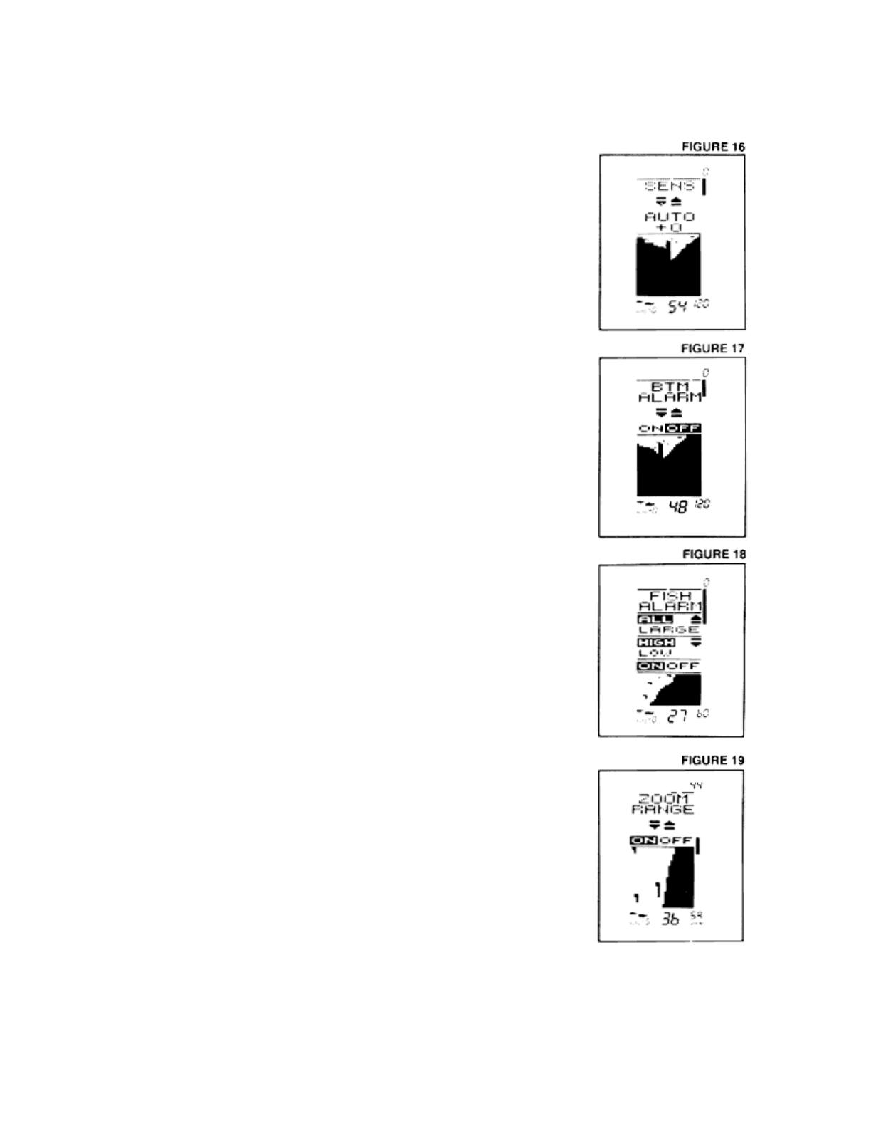
1. Sensitivity
Automatic setting: on, “O” or normal
As conditions change, the computer will automatically
increase or decrease the sensitivity setting. You can
manually increase or decrease the automatic setting from a
range of “+5” to “-5.” This level will maintain itself as long as
you have the unit on, automatically, as a result of the TCR’s
Sensitivity Bias feature. For example, if you set the sensitivity
at “+2,” the sensitivity will remain 2 settings higher than the
normal automatic settings until you turn the TCR off.
2. Bottom Alarm
Automatic setting: off
Use the On/Off button to activate the alarm, and the alarm
cursor appears on the screen. Then use the arrow keys to
adjust the depth at which the alarm will sound. You’ll hear a
continuous chirping sound when the bottom is within the area
that you’ve defined with the alarm cursor. This is a great
feature to use to alert you to shallow water, or to maintain
your position over structure.
3. Fish Alarm
Automatic setting: off
The fish alarm is easily activated by pressing the On/Off
button. This 2-level alarm can be set to sound for all fish, or
to ignore weaker signals and alarm only for stronger signals,
such as those from larger fish. You can also adjust the
volume of the fish alarm.
The controls for this function are a little different.
Pressing the Up arrow lets you switch between alarms for all
fish and large fish. The Down arrow controls volume of the
alarm.
Once the instructions have disappeared from the screen, it’s easy to tell which
alarm you have activated-the alarm for all fish shows both small and large fish symbols at
the bottom of the screen, while the “large only” alarm displays only a large fish symbol.
4. Zoom
Automatic setting: off
When zoom is activated by pressing On/Off, it creates a “window” of expanded, up-close
information. This window is marked by a cursor at the right of the screen and can be
moved up or down with the arrow buttons. The exact depths of the upper and lower limits
of the window are displayed as depth scales while you are in zoom.
The size of the zoom window changes as the depth range changes. The window
displays 7 ½ feet of up-close readings in the 15’ and 30’ ranges, and 15 feet in the 60’
and 120’ ranges. Keep in mind that, using your arrow buttons, you can move the zoom
window while the zoom is activated, without having to press Select again.
5. Bottom-Lock
Automatic setting: off
You can easily turn on the bottom-lock with the On/Off
button. When on, this function shows up-close zoom
readings in reference to the bottom. The size of the zoom
window depends on the depth range-7 ½ feet in the 15’
and 30’ ranges, and 15 feet in the 60’ and 120’ ranges.
The zoom window will automatically move up or down to
stay on the bottom, with the cursor showing you the
protion of the total depth range that is being displayed.
This is an ideal feature for finding structure or locating fish
near the bottom.
6. Display Speed
Automatic setting: one setting less than highest speed
The speed at which the TCR display moves depends on
the display speed setting, and it is easily changed by
pressing the Up arrow for a faster setting and the Down
arrow for a slower setting. Generally speaking, the higher
speed settings allow faster updates, while slower display
speeds provide more information.
7. Depth Range
Automatic setting: on
The TCR automatically finds the bottom, and then sets
and displays the ideal depth range when you turn the unit
on. If you choose to leave the auto range change on, the
bottom will remain “blacked in” for easy-to-understand
readings, and the depth ranges will change automatically.
Or, you can turn the auto change off, allowing you
to change the depth range manually. In this mode, the
bottom is not blacked in. This lets you see a double
bottom echo, which is preferred by some fishermen
because the width of the second echo can indicate bottom
texture.
  • Page 1 1
  • Page 2 2
  • Page 3 3
  • Page 4 4
  • Page 5 5
  • Page 6 6
  • Page 7 7
  • Page 8 8
  • Page 9 9
  • Page 10 10
  • Page 11 11
  • Page 12 12
  • Page 13 13
  • Page 14 14
  • Page 15 15
  • Page 16 16

Humminbird TCR 101 Operating instructions

Type
Operating instructions

Humminbird TCR 101: Experience Precision Fishfinding and Depth Measurement

The Humminbird TCR 101 is an advanced fishfinder designed to provide accurate depth readings and detailed fish arches. With its compact size and easy-to-use interface, it's perfect for anglers of all skill levels.

Features:

  • Clear, crisp display with adjustable backlighting for excellent visibility in all conditions
  • Dual-frequency sonar (200/455 kHz) for versatile fishfinding in various water depths
  • Fish ID+ technology for clear identification of fish species and sizes
  • Depth capability up to 600 feet for deep-water fishing

Ask a question and I''ll find the answer in the document

Finding information in a document is now easier with AI