Craftsman 113.221770 Owner's manual
- Category
- Circular saws
- Type
- Owner's manual
This manual is also suitable for

F•
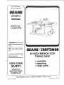
Save This Manual
For Future Reference
SEARS
owner's
manual
MODEL NO.
113,221770
I
Serial
Number
Model and serial numbers _I__RS
may be found at the rear of the
base.
You should record both model 1 0
and serial number in a safe
place for future use,
I
YOUR
SAFETY
READ ALL
INSTRUCTIONS
CAREFULLY
/CRA
iNCH BENCH
Part No, SP6048
TABLE SAW
AM
TOP
•assembly
•operating
°repair parts
Sears, Roebuck and Co., Hoffman Estates, IL 60179 U,S.A.
Printed in U.S.A, 6/97

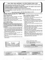
p* FULL ONE YEAR WARRANTY ON CRAFTSMAN TABLE SAW
If within one year from the date of purchase, this Craftsman Table Saw fails due to a defect in mate-
rial or workmanship, Sears will repair it, free of charge.
WARRANTY SERVICE IS AVAILABLE BY SIMPLY CONTACTING THE NEAREST SEARS SERVICE
CENTER/DEPARTMENT THROUGHOUT THE UNITED STATES.
This warranty applies only while this product is used in the United States.
This warranty gives you specific legal rights, and you may also have other rights which vary from
state to state.
Sears, Roebuck and Co., D/B17 WA Hoffman Estates, IL 60179
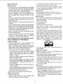
3afoty Instructions For Table Saw
Safety Signal Words
DANGER: means if the safety information is not followed
someone will be seriously injured or killed
WARNING:means if the safety information is not followed
someone could be seriously injured or killed.
CAUTION:means if the safety information is not followed
someone may be injured.
Before Using The Saw
WARNING: to avoid mistakes that could cause serf- I
ous, permanent injury, donor plug the table saw in _1
until the following steps have been satisfactorily I
completed. I
-Completely assemble and align saw (See pages 8-18)
• Learn the use and function of the ON-OFF switch (See
page 13) blade guard, spreader, anti-kickbackdevice,
miter gauge, rip fence, table insert, blade elevation and
blade tilt contro is (See page 21).
•Review and understand all safely instructions and
operating procedures inthis manual
• Review the maintenance methods for this saw (See
page 34-35).
• Find and read all the warning labels found on the saw
(shown below)
When installing Or Moving The Saw
Avoid dangerous environment.
• Use the saw in a dry, indoor place protected from rain.
Keep work area well lighted.
To avoid injury from unexpected saw movement.
•Bolt or clamp the saw to firm level surface where there
is plenty of morn to handle and properly support the
workpiece (See page 18-19).
•Support the saw so the table is level and the saw does
not rock.
• When using atable extension on any side of the saw,
prop up the outer end of the extension from the floor or
benchtop to keep the saw from tipping.
• Put the saw where neither, operators nor bystanders
must stand in linewith the sawblade.
•To avoid injury from electrical shock, make sure your
fingers de not touch the plug's metal prongs when
pluggingin or unplugging the saw.
•Never stand on tool. Serious injury could occur ifthe
tooltips or you accidentally hit the cutting tool. Do not
store any items above or near the tool where anyone
mightstand on thetool to reach them.
u o_ mm u) L) _;(9 m_ t--0) u.m
• • ••
DOUBLE INSULATED
When servicing use only identical
replacement parts.
I
li....
[' R_ld m_rluot before u_ng _sw. 6. W_n ripping, ule pullh _ft=:kwhen fence h= eel 2/ncbol or &Know bow t_ reduc:e _e _l_k of k.Jckb_k.
2 W,_=_ •_l_zy goggl_ that me, el AN_I Z87.1Stond_rdt. mo_'e |tom blade.
t3. Do rmt @_ _re_hl=r_d € u_$. 7. Whin ripping, =Jim p_llh block and _xllll_ IMIoe whln Ilsnce
tl _. Keep Id_a guard down lad In pile• _=_r through _:uts. _$ t_| foefwee_ 1/21114 2 _ncilel_ |rom bl_,de.
_l 5, Ke_p hand_ _t o_ pi|b zsfs_w blade. DOno_ make rip _uf$ rmrz_wer thlm 1/2 WCI'_.

Before Each Use
inspect your saw.
=To avoid injury from accidental starting, turn the switch
off unplug the saw. and remove the switch key before
raising or removing the guard, changing the cutting
tool, changing the setup, or adjusting anything.
• Check for alignment of moving parts, binding of mov-
ing parts, breakage of parts, saw stability, and any
other conditions that may affect the way the saw
works.
•If any part is missing, bent or broken in any way, or any
electrical part does not work properly, turn the saw off
and unplug the saw.
•Replace damaged or missing parts before using the
saw again.
° Use the sawblade guard, spreader and anti-kickback
pawls for any thru-sawing (whenever the blade comes
through the top of the workpiece). Make sure the anti-
kickback pawls work properly. Make sure the spreader
is in line with sawblade (See page 10-11).
o Make sure all clamps and locks are tight and no parts
have any excessive play.
• Remove adjusting keys and wrenches. Form a habit of
checking for and removing keys and adjusting
wrenches from table top before turning it on.
To Avoid injury From Jams, Slips Or Thrown
Pieces (Kickbacks Or Throwbacks)
Inspect your blade.
•Choose the right blade or cutting accessory for the
material and the type ot cutting you plan to do,
•Never use grinding wheels, abrasive cutoff wheels.
friction wheels (metal cutting blades) wire wheels or
buffing wheels. They can fly apart explosively.
°Choose and inspect your cuttingtool carefully:
-To avoid cutting tool failure and thrown shrapnel
(broken pieces of blade), use only 10 inch or smaller
blades or other cutting tools marked for speeds of
5000 rpm or higher.
- Always use unbroken, balanced blades designed to
fit this saw's 5/8 inch arbor.
-When thru-sawing (making cuts where the blade
comes through the workpiece top), always use a 10
inch diameter blade. This keeps the spreader in ctos-
est to the blade.
- Do not over tighten arbor nut. Use arbor wrenches to
"snug" it securely.
- Use only sharp blades with propedy set teeth. Con-
sult a professional blade sharpener when in doubt.
- Keep blades clean of gum and resin.
• Never use the saw without the proper blade insert.
Inspect your work area.
• Keep work area clean.
•Cluttered areas and benches invite accidents. Floor
must not be slippery from wax or sawdust.
-To avoid bums or other fire damage, never use the
saw near flammable licluids, vapors or gases.
-To avoid injury, don't do layout, assembly, or setup
work on the table while blade Is spinning. It could cut
or throw anything hitting the blade.
Plan your work
oPlan ahead to protect your eyes, hands, face. ears.
Use The Right Tool. Don't force tool or attachment to
do a job it was not designed for.
Dress for safety
°Do not wear loose clothing, gloves neckties or jewelry
(rings, wrist watches). They can get caught and draw
you into moving parts.
• Wear nonslip footwear.
•Tie back long hair.
• Roll long sleeves above the elbow.
• Noise levels vary widely. To avoid possible hearing
damage, wear ear plugs or muffs when using table
saw for hours at a time
° Any power saw can throw foreign objects into the
eyes. This car result in permanent eye damage. Wear
safety goggles (not glasses) that comply with ANSI
Z87.1 (shown on package). Everyday eyeglasses have
only impact resistant lenses. They are not safety
glasses. Safety goggles are available at Sears retail
stores. Glasses or goggles not in compliance with
ANSI Z87.1 could seriously hurt you when they break.
WEAR YOUR
=For dusty operations, wear a dust mask along with
safety goggles.
Inspect your workpiece.
•Make sure there are no nails or foreign objects in the
part ol the workpiece to be cut.
° When cutting irregularly shaped workpleces, plan your
work so it will not slip and pinch the blade:
° A piece of molding for example, must lie flat or be held
by a fixture or jig that wil! not let it twist, rock or slip
while being cut. Use jigs or fixtures where needed to
prevent workpiece shifting.
• Use a different, better suited type of tool for work that
can't be made stable.
Plan your cut,
• To avoid kickbacks and throwbacks - when a part or atl
of the workpiece binds on the blade and is thrown wo-
lently back toward the front of the saw:
- Never cut freehand. Always use either a rip fence.
miter gauge or fixture to position and guide the work.
so it won't twist or bind on the blade and kickback.
- Make sure there's no debris between the workpiece
and its supports.

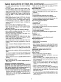
Safety Instructions for Table Saw (continued)
-Use extra caution with large, very small or awkward
workpieces:
• Use extra supports (tables, saw horses, blocks, etc.)
for any workpieces large enough to tip when not held
down to the table top. Never use another person as a
substitute for a table extension, or as additional sup-
port for a workplace that is longer or wider than the
basic saw table, or to help feed, support or pull lhe
workplace.
•Never confine the piece being cut off. that is, the piece
not against the fence, miter gauge or fixture. Never
hold it, clamp it, touch it, or use length stops against it,
It must be free to move. Jf confined, it could get
wedged against the blade and cause a kickback or
throwback.
• Never cut more than one workpiece at a time.
• Never turn your table saw "ON" before clearing every-
thing except the workplace and related support
devices off the table.
Plan the way you will push the workpiece through.
•Never pull the workplace through. Start and finish
the cutfrom the front ofthe table saw.
•Never put your fingers or hands in the path of the
sawblade or other cutting tool.
• Never reach in back of the cutting tool with either
hand to hold down, support the workpiece, remove
wood scraps, or for any other reason.
°Avoid hand positions where asudden slip could cause
fingers or hand to move into a sawblada or other cut-
tingtool.
•Oon't Overreach. Always keep good tooting and bal-
ance.
• Push the workplace against the rotation of the blade.
Never feed material into the cutting tool from the rear
ot the saw.
• Always push the workplace all the way past the saw-
blade.
•As much as possible, keep your face and body to one
side of the sawblade, out of line with a possible kick-
back or throwback.
• Make sure the top of the arbor or cutting too! turns
toward the front of the saw.
Keep children away.
• Keep all visitors a safe distance from the table saw.
+ Make sure bystanders are clear of the table saw and
workplace.
Don't force tool.
*Letthe blade reach full speed before cutting.
oItwill do the job better and safer at its designed rate.
-Feed the workpiece intothe saw only fast enough to let
the blade cut without bogging clown or binding.
Before freeing jammed material.
- Turn switch "OFF".
- Unplug the saw.
- Wait for all mov=ngparts to stop.
oCheck blade, spreader and fence for proper alignment
before starting again.
To avoid throwback of cut off pieces.
°Use the guard assembly.
To remove loose pieces beneath or trapped inside
the guard,
-Turn saw "OFF"
- Remove switch key.
=Wait for blade to stop before lifting the guard.
Before leaving the saw.
•Turn the saw off.
o Wait for blade to stop spinning.
-Unplug the saw.
oMake workshop chUd-proof.Lock the shop. Disconnect
master switches. Remove the yellow switch key, Store
it away from children and others not qualified to use
the tool
Additional Safety Instructions for
Rip Type Cuts
Before starting.
oNever use the miter gauge when ripping.
-Use a push stick whenever the fence is 2 or more
•Set the cutting tool as low as possible for the cut you're inches from the blade,
planning. *When thru-sawing, use an auxiliary fence and push
Avoid accidental starting, block whenever the fence must be between 1/2 and 2
-Make sure switch is "OFF" before plugging saw into a inches of the blade.
power outlet. •Never thru-saw rip cuts narrower than 1/2 inch. (See
Whenever Sawblade Is Spinning "Basic Saw Operations-Ripping and Bevel Ripping"
section.)
WARNING: Don't allow familiarity (gained from fre-
quent use of your table saw) cause a careless mis- !
take. Always remember that a careless fraction of a
second is enough to cause a severe injury.
•Before actually cutting with the saw, watch it while it
runsfor a short while. Ifit makes an unfamiliar noise or
vibrates a lot, stop immediately. Turn the saw off.
Unplug the saw. Do not restart until finding and cor-
recting the problem.
•Never rip anything shorter than 10" long.
•When using apush stick or push block, the trailing end
ot the board must be square. A push stick or block
against an uneven end could slip off or push the work
away from the fence.
•A Featherboard can help guide the workpiece. (See
"Basic Saw Operation-Using Featherboards for Thru-
Sawing" section.)

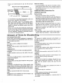
•Alwaysusefeatherboardsfor anynonthrurip type
cuts. Make From 3/4" Thick Solid Wood
E_ 24"
Ko...Abou, ! l
4-1/2 _ 5 -"-I Featherboard
• To avoid kickbacks and slips into the blade make sure
the rip fence is parallel to the sawblade.
oBefore fhru-sawing, check the anti-kickback pawls.
(See "Basic Saw Operation - Using The Rip Fence."
The pawls must stop a kickback once it has started.
Replace or sharpen anti-kickback pawls when points
become dul!,
•Plastic and composition (like hardboard) materials may
be cut on your saw. However. since these are usually
quite hard and slippery, the anti-kickback pawls may
not stop a kickback. Therefore, be especially careful in
your setup and cutting procedures.
When thru-sawing.
oTo avoid kickbacks and slips into the blade, always
push forward on the section of the workpiece between
the sawbtade and the rip fence, Never push forward on
the piece being cut off.
Additional Safety Instructions For
Crosscut Type Cuts
Before starting.
• Never use the rip fence when crosscutting.
oAn auxilia_, wood facing attached to the miter gauge can
help prevent workpiece twisting and throwbacks. Attach it
to the holes provided. Make the facing long enough and
big enough to support your work. Make sure. however, it
will not interferewith the sawblade guard_
- Use jigs or fixtures to hetp hold any piece too small to
extend across the full length of the miter gauge face
during the cut. This lets you properly hold the miter
gauge and workpiece and helps keep your hands
away from the blade,
When cutting.
-To avoid blade contact, always hold the miler gauge as
shown in "Basic Saw Operations - Using The Miler Gauge
Glossary of Terms for Woodworking
Anti-Kickback Pawls (AKP)
Device which, when properly maintained, is designed to
stop the workpiece from being kicked back at the opera-
tor during ripping operation.
Arbor
The shaft on which a cutting tool ismounted.
Bevel Cut
An angle cutting operation made through the face of the
workpiece.
Compound Cut
A simultaneous bevel and miter crosscutting operation.
Crosscut
Acutting operation made across the width of the work-
piece.
Dado
A non thru cut which produces a square sided notch or
trough in the workpiece.
Featherboard
A device which can help guide workpieces during riptype
operation.
Freehand
Performing acut without the use of fence (guide), miter
gauge, fixture, hold down or other proper device to pre-
vent the workpiece from twistingduring the cutting opera-
tion. Twisting of the workpiece can cause it to be thrown.
Gum
Asticky, sap based residue from wood products.
Heel
Misalignment of the sawblade such that the blade is not
parallel to the miter gauge groove.
Kerr
The amount of material removed by the blade in a
through cut. Also the slot produced by the blade in a non-
through or padial cut
Kickback
An uncontrolled grabbing and throwing of the workp_ece
back toward the front of the saw,
Leading End
The end of the workpiece which, during arip type opera-
tion. is pushed intothe cutting tool first.
Miter Cut
An angle cutting operation made across the width of the
workpiece.
Molding
A non through cut which produces aspecial shape in the
workpiece used for joining or decoration.
Push Stick
A device used to feed the workpiece through the saw
during narrow ripping type operations. The push stick
helps keep the operator's hands well away from the
blade.
Push Block
A device used for npping type operations too narrow to
a!low use of a push stick
Rabbet
A notch in the edge of aworkpiece.
Resin
A sticky, sap based substance that has hardened.
Revolutions Per Minute (RPM)
The number of turns completed by a spinning object in
one minute.

Glossary of Terms for Woodworking (continued)
Rip Cut
A cutting operation along the lenglh of the workpiece.
Sawblade Path
The area oi the workpiece or table top directly in linewith
either the tmvetof the blade or the part of the workpiece
whichwill be, or has been cut by the blade.
Set
The distance that the tip of the sawblade tooth is bent (or
set) outward from the face of the blade.
Throw-Back
Throwing of pieces in a manner similar to akickback.
Thru-Sawing
Any cutting operation where the blade extends com-
pletely through lhe thickness of the workpiece.
Trailing End
The workpiece end last cut bythe blade in a rippingoper-
ation.
Workpiece
The item on which the cutting operation is being per-
lormed. The surfaces of a workpiece are commonly
referred to as faces, ends, and edges.
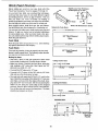
Motor Specifications and Electrical Requirements
Power Supply and Motor Specifications
The AC motor used in this saw is a universal, nonrevers-
ible type having the following specifications:
Maximum Developed HP ........................................ 2-1/2
Voltage ...................................................................... 120
Amperes ...................................................................... 13
Hedz (Cycles) ............................................................ 60
Phase ................................................................... Single
RPM ......................................................................... 4700
Rotation of Shaft ................................ Counterclockwise
WARNING: To avoid electrical hazards, fire haz-
ards, or damage to the tool, use proper circuit pro-
tection. Yoursaw is wired at the factory for 120v
operation. Connect to a 120v, 15-amp branch cir-
worn or cut, or damaged in any way, have it
•replaced immediately.
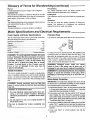
Polarized Plug
Your unit has aplug that looks like the one shown below.
To reduce the risk of electrical shock, this appliance has
a polarized plug (one blade is wider than the other). This
plug will fit in apolarized outlet only one way. If the plug
does not fit fully in the outlet, reverse plug. If it still does
not fit, contact a qualified electrician to install the proper
outlet. Do not change the plug in any way.
WARNING: Damaged power cords can cause
shock or fires. If the power cord is worn, cut, or
damaged in any way, have it replaced immediately.
tion. ' e
IMPORTANT. To avoid motor damag ,this motor should
WARNING: Double insulation does not take the l be blown out or vacuumed frequently to keep sawdust
place of normal safety precautions when operating from interfering with normal motor ventilation,
this tool. ' 1, Connect this tool to a120v, 15-amp branch circuitWith
DANGER: To avoid electrocution:
1. Use only identical replacement parts when ser-
vicing a tool with double insulation. Servicing
should be performed by a qualified service tech-
nician.
2. Do not expose to rain, use in damp location or
where floor is wet.
This tool is intended for indoor residential use
only.
a15-amp time delay fuse or circuit breaker. Using the
'aes "c " " " "
2.1f the motor won t st rt,_tumth wit h OFF immedi-
ately. Unplug The Tool. Check the sawblade to make
sure it turns freely. If the blade is free. try to start the
motor again. If the motor still does not starl, refer to the
"Troubleshooting Chart" on page 35.
3. If the motor suddenly stalls while cutting wood, turn the
switch "OFF", unplug the tool, and tree the blade from
the wood. The motor may now be restarted and the cut
finished.
4. Fuses may "blow" or circuit breakers may trip fre-
quently if:

a.MotorIs Overloaded.Overloadingcanoccurifyou 5.
feedtoorapidlyormaketoomanystart!stopsin a
shorttime.
b.Voltagesnotmorethan10%aboveor belowthe
nameplatevoltagecan handlenormalloads.For
heavyloads,however,thevoltageat motortermi-
nalsmustequalthevoltagespecifiedonnameplate.
Overload Protection
Your saw features a reset overload relay button. If the
motor stops running or fails to start (due to feed pres-
sure too fast, dull blade or low voltage), turn switch
"OFF", let the motor cool three to five minutes and
push the reset button, which resets the overload
device and allows you to turn the saw back on.
WARNING: The ON/OFF switch should be in the off
position, and the plug removed from the power
source while the cool down takes place to prevent
accidental starting when the reset button is
pushed, Overheating may be caused by misaligned
parts or dull blade, Inspect your saw for proper
setup before using it again,
Most motor troubles may be traced to Boose or #_c:or-
rect connections, overload, low voltage (such as sm_ll
size wire in the supply circuit) or h_overly tong s,JpP{Y
circuit wire. Always check the connections, the load
and the supply circuit whenever motor doesn't work
well. Check wire sizes and length with the Wire S_ze
Chart.
Wire Size
NOTE: Make sure the proper extension cord is used _d
is in good condition.
The use of any extension cord wi!l cause some toss of
power, To keep this to a rninimum and to prevent over
heating and motor burnout, use the table to determine
the minimum wire size (A.W,G.) extension cord.
Extension Cord
Length
0-25
26-50
Table of Contents
Warranty ......................................................................... 2
Safety Instructions For Table Saw ............................... 2
Safety Signal Words: ................................................... 2
Before Using The Saw: ............................................... 2
When Installing Or Moving The Saw: ......................... 2
Before Each Use: ....................................................... 3
Whenever Sawblade Is Spinning: ............................... 4
Additional Safety Instructions for: ................................ 4
Rip Type Cuts.............................................................. 4
Before starting ............................................................. 4
Additional Safety Instructions For: ........................... _..5
Crosscut Type Cuts ..................................................... 5
Glossary of Terms for Woodworking .............................. 5
Motor Specifications and Elec{rical Requirements ........ 6
Power Supply and Motor Specifications ...................... 6
Double Insulation ........................................................ 6
Polarized Plug ............................................................. 6
Motor Safety Protection ............................................... 6
Overload Protection ..................................................... 7
Wire Size ..................................................................... 7
Table of Contents ........................................................... 7
Unpacking and Checking Contents ................................ 8
Tools Needed .............................................................. 8
Table of Loose Parts ................................................... 8
List of Loose Parts in the Box and Bags ..................... 9
Assembling Handle to Handwheel ................................. 9
Blade Guard Assembly ................................................ 10
Blade Guard Alignment ................................................ 11
Checking Anti-kickback Pawls .................................... 11
Rip Fence Assembly and Adjustment .......................... 12
Rip Fence Alignment .................................................... 12
Rip Fence Indicator Adjustment ................................... 13
Miter Gauge and indicator Adjustment ........................ 13
On-Off Switch ............................................................... 13
Blade Tilting Control and Lock Lever Adjustment ........ 14
Adjusting 90 and 45 Degree Positive Stops ................. 14
Adjusting Positive Stop at 90 Degrees ...................... 14
Adjusting Positive Stop at 45 Degrees ...................... 14
Blade Tilt Indicator Adjustment .................................... 15
Wire Sizes Required
(A.W.G,)
t10-120V
14
12
Checking Blade Parallel to the Miter Gauge Groove .. 15
Adjusting Blade Parallel to Miter Gauge Groove ......... 16
Removing Sawblade .................................................... 17
Installing Sawblade ...................................................... t 7
Mounting Table Saw to Workbench, Cabinet or Legsei 18
Workbench Mounting Using Hardware ..................... 18
Workbench Mounting Using "C" Clamps ................... 18
Cabinet or Legset Mounting Using Hardware ........... 18
Assembly ................................................................... 19
Getting to Know Your Table Saw ................................ 20
Work Feed Devices ...................................................... 22
Push Stick ................................................................. 22
Push Block ............................................................... 22
Auxiliary Fence ......................................................... 23
Safety Instructions for Basic Saw Operations .............. 24
Before Each Use: ...................................................... 24
Whenever Sawblade Is Spinning: ............................. 25;
Basic Saw Operations .................................................. 26
Additional Safety Instructions for Crosscutting .......... 26
Crosscutting ... ........... 26
Repetitive Crosscutting ............................................. 27
.............. 27
Miter Crosscutting .....................................
Bevel Crosscutting .................................................. 27
Compound Miter Crosscutting ................................... 28
Additional Safety Instructions for Rip Cuts ............... 28
Ripping .. ............................................... 29
Bevel Ripping ........................................................... 30
Resawing ................................................................... 31
Dadoing .......................................................................
Rabbeting .................................................................. 33
Ploughing or Molding ................................................. 33
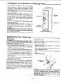
Installation and Operation of Molding Head ................. 34
Maintaining Your Table Saw ..................................... 34
Maintenance .............................................................. 34
Lubrication ............................................ 35
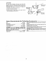
Sears Recommends the Fol ow ng Accessor es ......... 35
......................................... 3_
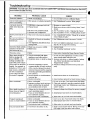
Troubleshooting ..- .............37
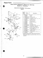
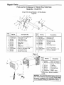
Repair Parts ....................................................43
Notes ......................................................................

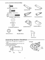
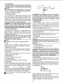
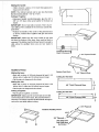
Unpacking and Checking Contents
Tools Needed
#2 Phillips Screwdriver
Medium Screwdriver
Adjustable Wrench
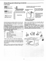
Combination Square
Combination Square must be true. Check its
accuracy as shown below.
Draw light line on board
alon edge
Select the straight edge of
3/4" thick board. This edge
must be perfectly straight,
/
NOTE: The square and
straight edge are used
to align the saw.
They must be accurate
if the saw is to be
aligned properly,
Should be gap or overlap
here when square is flipped
over in dotted position
Separate all parts lrom packing material and check each
one with the illustration and the list of Loose Parts to
make certain all items are accounted for, before discard-
ing any packing material.
wARNING: If any parts are missing, do not attempt I
to assemble the table saw, plug in the power cord !
or turn the switch on until the missing parts are
obtained and are installed correctly.
Table of Loose Parts
Item Description Qty
A Table Saw Assembly ....................................... 1
B Miter Gauge ..................................................... 1
C Blade Guard and Spreader .............................. 1
D Rip Fence (Without Handle) ............................ 1
E Owner's Manual ............................................... 1
F Bag ol Loose Parts ......................................... *
Apply a coal of automobile wax to the table. Wipe al
parts thoroughly with a clean, dry cloth. This will reduce
friction when pushing workpiece.
WARNING: For your own safety, never connect
plug to power source outlet until all assembly
steps are complete, and you have read and under-
stand the safety and operating instructions.
B
bag together and separate from contents of other bags.

List of Loose Parts in the Box and Bags
Hex Screw - 1/4-20 x 1/2" (2)
Carriage Bolt - 1/4-20 x 718" (1)
Hex Screw - 1/4-20 x 2-1/8" (1)
Flat Washer (1)
©
1/4" External Lockwasher 14)
Q
Nut Hex 5116-18 (1)
Shaft Wrench (1)
Handle (Rip Fence) (1)
Spreader Bracket (1)
Wing Nut 114-20 (1)
Arbor Wrench (1)
Knob (Handwheel) (1)
Spreader Support (1)
Assembling Handle to Handwheel
1. Thread screw into tapped hole in handwheel, as
shown.
2. When properly assembled, the knob will rotate freely
with only a small amount of play.
3. Lock nut against handwheel.
1/3_
Screw \ \
Nut Knob
Switch Key (1)
Handwheel

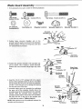
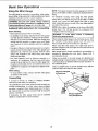
Blade Guard Assembly
1. From among the loose parts, locate the following hardware:
Hex Screw -
1/4-20 x 1t2" (2)
114"External Flat Washer (1)
Lockwas her (4)
Carriage Bolt - 1/4-20 x7/8" (1)
Wing Nut 1/4-20 (1)
0
Hex Screw - 114-20 x 2-1/8" (1)
0
Spreader Support I1) Spreader Bracket (1)
2. Position large recessed shoulder end of the
spreader support against end of pivot rod and fasten
to table using the 1/4-20x2-1/8" long hex screw and
1/4" external tooth Iockwasher.
/_ _asher 1/4"
_X Screw ,,
1/4-20 x 2-1/8
3. Position the spreader bracket to the spreader sup-
port as shown. The 1/4-20xl/2" screws and lock-
washers are to be assembled finger tight only at this
time.
.. Spreader
Support
Blade Guard
Bracket and Spreader
4. Insert the 1/4-20 x7/8" carriage bolt in the square
feature o1the spreader bracket as shown. Assemble
the flat washer first, then the 1/4 external Iockwasher
and the 1/4-20 wing nut on the carriage holt leaving
the wing nut loose at this time.
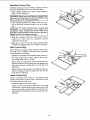
5. Assemble blade guard and spreader by positioning
the open slot in the spreader directly above the
shouldered part of the rivet attached to the spreader
bracket. Slide the spreader down between the
spreader bracket and the head of the rivet until either
the open slot sets on the rivet or the spreader sets Win
on the table top surface. Tighten wing nut.
NOTE: Both washers must be positioned between the
spreader and the wing nut.
Spreader
Shouldered
Lockwasher 114 Carriage Bolt
1/2-20x7/8
10

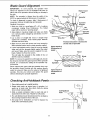
Blade Guard Alignment
IMPORTANT: To work properly, the spreader must
always be adjusted so the cut workpiece will pass on
either side of the spreader without binding or skewing to
the side.
NOTE: The spreader is thinner than the width of the
KERF by approximately six thicknesses of newspaper.
To check if alignment is proper, slide 3 thicknesses of
newspaper between straight edge and spreader.
Readjust ifnecessary.
1. Make two folds in a small piece (6" x6") of ordinary
newspaper making three thicknesses. The folded
paper will be used as a "spacing gauge".
2. Raise blade to maximum height and make sure blade
is in vertical position (straight up and down) or at "0_"
blade angle.
3. Lay apiece of straight flat wood or straight edge
against the sawblade. Insert folded paper between
spreader and wood strip.
4. Make sure the three hex screws are loose enough to
slide spreader bracket and to rotate spreader support.
5. Lift the anti-kickback pawl to clear the wood or straight
edge and hold the spreader tightly against the paper
and wood. Make sure the wood is against the saw-
blade. Tighten the three hex screws.
This will align the spreader in the middle of the cut
(KERF) made by sawblade.
NOTE: To remove the guard for non-through cuts, loosen
the wing nut and slide the guard upward off the soreader
bracket. Do not disturb the setting of the spreader sup-
port bracket.
When replacing the guard, slide the spreader down onto
the spreader support bracket with the washers directly
under the wing nut. Make sure the wing nut is tightened
securely. This lets you remove and replace the guard
without disturbing the spreader alignment.
Blade Guard
t/Arm
BladENewspaperL__Spreader
Straigh_---'c_-_-.-_J'_-_! 'J"_.._Snreader
Position flatwasher &!ockwasher
on this side of spreader
Space equals 3
thicknesses of
paper _Wood
\ J Blade
/
/
/
/
/
Space equals 3
thicknesses of
Looking Down on Saw
paper
Checking Anti-kickback Pawls
1. Raise blade guard up to upright position.
2. Rotate both pawls up toward rear el spreader. Let
pawls go to make sure they return freely by spring
force to their normal position.
3. Slide asample workpiece under a pawl and pull it
toward the front of the saw. Repeat for both pawls.
4. The anti-kickback pawl should prevent the workpiece
from moving toward the front of the saw.
5. See page 33 for instructions on how to sharpen the
teeth of the anti-kickback pawls.
Anti-Kickback /
t°' i
,laise
Pawls
11

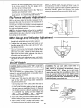
Rip Fence Assembly and Adjustment
WARNING: To prevent personal injury, always dis- I
connect plug from power source when making L
adjustments.
t_ Thread 5/16-18 nut all the way onto the fence locking
handle.
2. Thread rip fence locking handle into cam until tight.
Lock the nut against cam with wrench.
3. Place the rip fence on the table and lower the rip fence
locking handle until the rip fence is secure to front rail.
4. Check to see if rear clamp on the dp fence is loose, If
not, turn the rip fence adjustment screw counterclock-
wise until the rear clamp on the rip fen ce is loose with
the fence assembly locked to the front rail.
5. With fence assembly locked to front rail, turn the rip
fence adjustment screw clockwise until rear clamp is
snug.
6_Raise the rip fence lockinghandle.
7. Turn the rip fence adjustment screw clockwise an addi-
tional 1/2 turn.
8. Check the rip fence by applying moderate side pres-
sure to the rear of the fence assembly. If the rip fence
deflects easily raise the rip fence locking handle and
turnthe rip fence adjustment screw clockwise another
1/4turn.
9. Check rip fence again by applying moderate side pres-
sure to the rear of the fence assembly. If necessary
repeat step 8 until rip fence is secure.
NOTE: Overtightening the rip fence adjustment screw
may cause the rip fence to be loose on the front table rail.
Rip Fence Alignment
' WARNING: To prevent personal injury, always dis-
connect plug from power source when making
adjustments.
Q
Nut Hex 5/16-18 (1) Handle (Rip Fence) (1)
Rear Clamp
O
Miter Gauge Rip Fence
ICAUTION: The rip fence must be aligned parallel to
the blade to minimize the danger of kickback. For ....
convenience, the rip fence will be aligned parallel
to the miter gauge slot. The sawblade will be set or
adjusted parallel to the slot later.
1. Place the ri_
cent to the miter gauge groove.
2. Lower the rip fence locking handle to secure the rip
fence.
3. Check to see that the edge of the ri_
with the miter gauge groove
If the rip fence is not parallel:
oRaise the rip fence locking handle.
°Loosen the two hex head screws located on top of
the rip fence.
•Align the rip fence parallel to the miter gauge groove,
=Lower the rip fence locking handle.
-Tighten the two hex head screws previously loos-
ened.
Adjusting Screws
12

• Raise the rip fence rocking handle, move and return NOTE: To always obtain the best alignment of the rip
the rip fence adjacent to the miter gauge groove, fence, develop the habit ol holding the front casting on
lower the rip fence locking handle, the lence back against the table top while tightening the
• Repeat and recheck steps 8 and 9 in the "Rip Fence fence lock handle. Tighten the rip |ence tock handle
Assembly and Adjustment" section, securely to prevent rip fence movement while sawing.
• The rip fence should now be parallel to the miter
gauge groove, It not. repeat steps and recheck.
Rip Fence Indicator Adjustment ........
With the rip fence locked to the table measure the dis-
tance from the side of the rip fence to the nearest side of
the blade. The indicator should point to the same marking
on the scale. If it does not, loosen the screw holding the
indicator, move the indicator to the correct marking on
the scale and tighten the screw.
HINT: The rip fence indicator will need to be readjusted
whenever a thicker or thinner blade is installed. When
making critical cuts, make a trial cut on scrap wood rather
than relying on the rip scales.
Miter Gauge and Indicator
1. Check to make sure the miter gauge will slide
Scai____1_
Screw/
Adjustment
freely
through both entire table grooves before using it,
2. To adjust the miter gauge, loosen lock knob and set
the miter gauge body so the scale is at the 90' mark,
then tighten lock knob,
3. Make a cut on a piece of scrap wood. Check it with a
square to see if the piece ol wood was cut at 90°. Ifthe
piece was not cut 90°. adjust the miter gauge body,
tighten lock knob and make additional cuts until you
are ceratin you have made a 90° cut.
4. Loosen the miter scale adjustment screw set the indi-
cator point on the 90° mark on the scale and tighten
screw,
On-Off Switch
ICAUTION: Before turning switch "ON", make sure I
the blade guard is correctly installed and operating I
properly.
The On-Off switch has a locking feature. This feature is
intended to prevent unauthorized and possible hazard-
ous use by children and others.
1_ insert key into switch.
2. To turn saw "ON", stand to either side of the blade.
never in line with it: insert finger under switch lever
and pull end of lever out.
-After turning switch "ON". always allow the blade to
come up to full speed before cutting.
-Do not cycle the motor switch on and off rapidly as
this may cause the sawblade to loosen. In the event
this should ever occur, allow the sawblade to come
to a complete stop, unplug saw and retighten the
arbor nut normally, not excessively.
-Never leave the saw while the power is "ON".
3. To turn saw "OFF", push lever in. Never leave the saw
until the cutting tool has come to a complete stop.
4. To lock switch in "OFF" position, hold switch in with
one hand and remove key with the other hand.
WARNING: For your own safety, lower blade or
other cutting tool below table surface. (If blade is
tilted, return it to vertical, 90 ° position). Always
lock the switch "OFF". When saw is not in use,
remove key and keep it in a safe place. Also, in the
event of a power failure (all of your lights go out)
turn switch off and lock it by removing the key.
This will prevent the saw from starting up again
when the power comes back on.
Switch Key
13

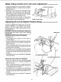
Blade Tilting Control and Lock Lever Adjustment
1. Loosen blade tilting lock lever and slide the elevation
handwheel until blade is at desired angle and tighten
blade tilt lock lever.
2. If blade lock lever interferes with some object before
blade tilting control mechanism is held tight or rigid,
pull lock lever out and rotate lock Fever counterclock-
wise to another position. Tighten lock lever. Recheck
for proper adjustment of blade tilt lock lever,
3. I1 lock lever won1 loosen enough so blade can be
tilted, pull lock lever out and rotate lever clockwise to
another position. Tighten blade lock lever,
EJevation Handwheel
Blade Tilt Lock Lever
Adjusting 90 and 45 Degree Positive Stops
Your saw is equipped with positive stops for last and
accurate positioning ol the sawblade at 90 and 45
degrees to the table. Always measure blade position
from the left side of the blade. Blade insert may not be
flush with table top.
IWARNING: To from source _vhen making I
prevent personal injury, ahvays dis- I
connect plug power
adjustments. !
Adjusting Positive Stop at 90 Degrees
1. Unplug the saw.
2. Turn elevation wheel clockwise and raise blade to
maximum height,
3. Loosen the blade tilt lock lever and push the elevation
wheel to the left as far as possible and tighten the
blade tilt lock lever
4. Place a combination square on the table with one end
of square against the blade as shown and checkto see
ifthe blade is 90 ° to the table.
5. If the blade is not 90° to the table, loosen the blade tilt
lock lever, loosen 90° adjustment screw (A) a few turns
and push the elevation wheel until the blade is 90 ° to
the table
6. Tighten blade tilt lock lever and tighten 90°adjustment
screw until it stops.
\\
Adjusting Positive Stop at 45 Degrees
1. Loosen the blade tilt lock lever and push elevation
wheel to the right as far as possible and tighten the
blade tilt lock lever.
2. Place a combination square on the table with one end
ol the square against the table as shown, and check to
see if the blade is 45° to the table,
3. It the blade is not 45 ° to the table loosen the blade tilt
lock lever, loosen 45 ° adjustment screw (B) a few turns
and push the elevation wheel until the blade is 45 ° to
the table.
4. Tighten blade tilt lock lever and tighten 45° adjustment
screw until it stops,
°" t
90 Adiustmen Screw (A)
Blade insert
45°Adjustment Screw (B)
/
/
/
14

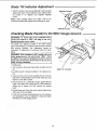
Blade Tilt Indicator Adjustment
1. With 90° positive stop set and blade tilt control pushed
against this stop, loosen indicator screw, adjust indica-
tor pointer to "0" degrees and retighten indicator
screw.
NOTE: When making critical cuts. make a trial cut on
scrap wood rather than relying on the tilt scale or stops.
Indicator Pointer
Indicator Screw
Checking Blade Parallel to the Miter Gauge Groove
WARNING: To avoid injury from accidental start,
make sure switch is "OFF" and plug is not con-
nected to power source outlet.
The blade was adjusted parallel to the miter gauge
groove at the factory, in order to insure accurate cuts and
help prevent kickback, this adjustment should be
rechecked, If adjustment is necessary follow the steps
below.
WARNING: If the sawblade is NOT parallel with the
miter gauge groove, it is said to have "HEEL". This
condition can cause the workpiece to bind or move
away from the rip fence at the end of arip cut, pos-
sibly causing a kickback.
1, Unplug saw.
2. Turn elevation whee, and raise blade as high as it will
go.
3. Lift blade guard if already installed, to its highest posi-
tion.
4. Select a tooth on the front of sawblade that is set to the
right when viewing blade from the front of the saw. and
mark this tooth with a pencil
5. Place the base of a combination square against the left
edge of the right miter gauge groove, and extend the
sliding rule ol square so it just touches the marked
tooth.
6. Rotate blade and check the same marked blade tooth
at the rear of the saw table.
7. If the front and back measurements are not identicaL,
the mechanism must be adjusted to make the blade
PARALLEL to miter gauge groove,
/
/
Mark "X" on tooth
15

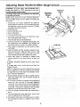
Adjusting Blade Parallel to Miter Gauge Groove --
WARNING: To avoid injury from accidental start,
make sure switch is "OFF" and plug is not con-
nected to power source outlet.
ICAUTION: Fold a piece of cardboard over the blade
Ito protect your hand
NOTE: Always review the section "Checking Blade Par-
allel to the Miter Gauge Groove" before proceeding with
this section.
1. Should your saw require adjustment the alignment
screws must be loosened It you are unable to loosen
the alignment screws from the top using a #2 Phillips
screwdriver proceed as follows:
2. Unplug the saw.
3. Remove the table insert.
4. Remove the blade.
5. Turn saw upside down.
6. Locate the 4 nuts attached to the alignment screws
(A). Loosen these nuts 1/2 turn.
7. Turn saw right side up and install blade
8. Loosen 1/2 turn the four alignment screws (A) in the
top of table next to the sawblade. This will allow the
mechanism below the table to be shifted sideways.
9. Fold a piece of cardboard over the blade to protect
your hands.
10. Grasp the blade and the spreader support mecha-
nism and move it to either the right or left a small
amount as needed to make the square Iouch the
same amount front and rear. Tighten one screw.
11. Check with square to determine if marked tooth
touches square by the same amount at front and
rear.
If it does, alternately tighten the other three screws
slowty.
If it does not, loosen screws and move blade the
required amount.
NOTE: If adjustment cannot be achieved by loosening
the four alignmen! screws (A), loosen the two second-
ary alignment screws (B) only if it is absolutely neces-
sary to make this adjustment.
12. Recheck blade clearance to table and table insert to
Secondary
ALignment
Screws
Alignment
Screws
(A)
Cardboard
make sure blade does not hit at both 90 and 45
degree blade tilt.
13. If you cannot complete the alignment using alignment
screws (A), then proceed to secondary alignment
screws (B), if you cannot loosen secondary alignment
screws (B), remove blade and turn saw upside down,
Locate the 2 nuts that are attached to the secondary
alignment screws IB) and loosen nuts 1/2 turn.
14. Turn saw upright, reinstall blade and repeat steps 1
thru 5.
15. Once saw blade has been aligned, the screws need
only to be tightened from the top side
16. Reinstall the table insert and blade guard. Continue
the assembly procedure as outlined in your owners
manual.
16

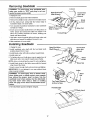
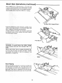
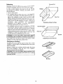
Removing Sawblade
WARNING: To avoid injury from accidental start,
make sure switch is "OFF" and plug is not con-
nected to power source outlet.
1. Unplug the saw.
2. Remove blade guard and retain hardware,
3. Remove the phillipshead screws from the blade insert.
4. Lift the blade insert noting that the formed edge is
toward the blade. Set insert aside.
5. Turn elevation handwheel clockwise to raise sawblade
as high as it will go.
6. Insert open end arbor shaft wrench over flal portions ol
motor spacer and closed end arbor nut wrench over
arbor nut. Position wrenches as shown holding your
hands well above blade.
7. Hold arbor wrench against table and loosen arbor nut
with arbor nut wrench by pulling it forward to you.
8. Slide sawblade off motor shaft.
Installing Sawblade
1. Unplug the saw.
2. Install sawblade onto shaft with the top blade teeth
pointing toward front of saw.
3_Install blade collar with hollow surface toward blade.
4. Install arbor nut.
5. To tighten arbor nut, hold arbor wrench against rear of
table, push arbor nut wrench towards rear of table,
NOTE: Arbor nut should just be snug. Do not overtighten.
6. Install blade insert in the table recess with its formed
edge toward the blade.
7. Insert screws through front and rear holes and tighten.
IMPORTANT: Do not attempt to run saw without blade
collar properly installed.
WARNING: To avoid injury from athrown work-
piece, blade parts, or blade contact, never operate
saw without the proper insert in place. Use the
sawblade insert when sawing. Use the dado/mold-
ing head insert when using a dado or molding
head. See page 34 for Sears recommended acces-
sories.
8. Re-install blade guard and tighten wingnut.
Loosen
Open End Arbor"_ "_-"_'_ Closed End
Shaft Wrench _)jArbor Nut
-- \ _-_ f/"...Wrench
Stop or=Table f'° _" d_i/ /-'Arbor Nut
J
Tighten
Closed End
;k_ Arbor Nut
ench
LBlade
_'-Insert
_r// ! Arbor Nut
Collar
Top Teeth Pointing "_._'_ '_--_"_
to Front of Saw
Formed Edge
\
\
17

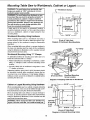
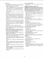
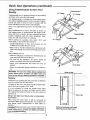
Mounting Table Saw to Workbench, Cabinet or Legset --
WARNING: To avoid injury from accidental start,
make sure switch is "OFF" and plug is not con-
nected to power source outlet.
WARNING: To avoid injury from kickback or saw
movement the saw must be properly secured to a
sturdy workbench, cabinet or legset. Casters if
provided onthe cabinet or legset must be locked
during saw operation. Ifthere is any tendency for
the saw to move or rock during operation, this
must be corrected immediately.
If table saw is to be used in a permanent location,
should be fastened securely to a firm supporting surface
such as a workbench, cabinet or tegset using the four
mounting' holes.
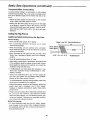
Workbench Mounting Using Hardware
When mounting table saw to a workbench and using a
vacuum hookup, holes should be drilled through the sup-
porting surface of the workbench using the dimensions
illustrated.
When mounting table saw without a vacuum hookup to
the base, an opening must be made in the workbench
using the dimensions illustrated, so the sawdust can fall
away from the Saw base area.
Workbench Mounting Using "C" Clamps
An alternative method of securing your table saw is to
fasten the saw base with "C" clamps.
1. Follow instructionsfor mounting to workbench, substi-
tuting "C" clamps in each recessed mounting screw
Iocalion.
2. Securely clamp saw to workbench using three or 10ur
"C" clamps, as shown.
Supporting surlace where saw is to be mounted should
be examined carefully after mounting to insure that no
rnovement can occur during use. If any tipping, sliding or
walking is noted, secure the workbench or cabinet before
operating the table saw.
--- Workbench Surface
................ m ...... i
I
I I 3/8" Dia!'
=,'Opening if
Vacuum
is not used
;o ---T
9/1_"
5_
!
_0_
I-_-- 16_9116"--------_1
(Front of Table Saw)
Diagram of Workbench Mounting Holes
"C" Clamps
(Front and Rear)
%__. _-_ _"C" Clamp
Recessed Mounting
Screw Location
Diagram of Clamping Table Saw to Workbench
Cabinet or Legset Mounting Using Hardware
When mounting table saw to a cabinet or legset and using
avacuum hookup, holes should be drilled through a 3/4"
thick plywood base using the dimensions illustrated.
When mounting table saw without a vacuum hookup to
the base, an opening must be made in the plywood base
using the dimensions illustrated, so the sawdust can fall
away from the saw base area.
IWARNING: Never clamp the table saw directly to a I
legset. The saw could fall. You could be badly cut. I
-- 20"1/2"'--"---_ I
3/8" Dia. "-" I"- 2-1/2"
2-7/16" ,
T T
. 21"
16 1/8"
Opening_
if vacuum|
is not |O
used l-._--- 16-9116" _ I-,=_--2"
(Front of Table Saw
Diagram of Cabinet Mounting Holes
18

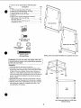
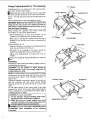
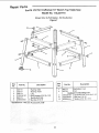
1. From the loose parts find the following pads.
Item Description Qty
A Leg ................................................................................. 4
1 Top Front and Rear Brace (18" long) ............................ 2
2 Bottom Front and Rear Brace (22" long) ...................... 2
3 Top side brace (17-1/2" long) ........................................ 2
4 Bottom side brace (22-1/2" long) ................................... 2
5 Leg Pad ....................................................................... 4
6 Bag of Loose Parts Containing the Following:
Bolt carriage, 5/t 6-18 x 5/8" long .............................. 24
Hex Nuts, 5/16-18 ................................................. 28
Hex Head Screws. 5/16-18 x 2-1/2 .............................. 4
Lockwashers. 5/16 ..................................................... 4
5/16-18 x 5/8" Long
Bolt Carriage
© ©
5/16 In. External 5/16-18
Lockwasher Hex Nut
5/16-18 x 2-1/2"
Hex Head Screw
1
A
A
Front and Rear
3
Right and Left Sides
54
NOTE: Letter and number identifiers are stamped into parts.
WARNING: For your own safety, turn switch "OFF" and
remove plug from power source outlet before mounting
power tool onto leg set.
Assembly
1. Install one leg pad onto bottom of each leg.
2. Assemble front and rear sections first by insertingscrews
through legs then through braces. Braces are always inside
of legs and top brace flanges. Shorter side of braces are
always up. Finger tighten screws and nuts as adjustment
may be necessary later. Assemble front and rear sections as
shown. Pay particular attention to the hole and screw pat-
terns as shown ......
3. Assemble side braces to front and rear sections of leg set
4. Hardware to mount the power tool to the leg set is supplied.
5. After the power tool is mounted to the leg set you may then
shift the leg set to adjust for a slightly unlevel floor. Then
securely tighten all hardware.
Front Side
W
Top
View
Use Outermost Holes for Table Saws
(Shaded Areas)
19

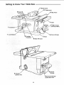
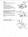
Getting to Know Your Table Saw
6 Blade Tilt
/1 1Blade Guard
/
/ /12 Table insert
/
10 Rip Fence
7 Handwheel /
_'4 Table
3 Miter Gauge
(stored position)
1 On-Off Switch
Overload
Protection _"_ 5 Base
8 Blade Tilt Scale
Rip Fence Storage
Ejection Port
I Wrench
Storage
ge
on Non-thru Cuts
2O
Page is loading ...
Page is loading ...
Page is loading ...
Page is loading ...
Page is loading ...
Page is loading ...
Page is loading ...
Page is loading ...
Page is loading ...
Page is loading ...
Page is loading ...
Page is loading ...
Page is loading ...
Page is loading ...
Page is loading ...
Page is loading ...
Page is loading ...
Page is loading ...
Page is loading ...
Page is loading ...
Page is loading ...
Page is loading ...
Page is loading ...
Page is loading ...
-
 1
1
-
 2
2
-
 3
3
-
 4
4
-
 5
5
-
 6
6
-
 7
7
-
 8
8
-
 9
9
-
 10
10
-
 11
11
-
 12
12
-
 13
13
-
 14
14
-
 15
15
-
 16
16
-
 17
17
-
 18
18
-
 19
19
-
 20
20
-
 21
21
-
 22
22
-
 23
23
-
 24
24
-
 25
25
-
 26
26
-
 27
27
-
 28
28
-
 29
29
-
 30
30
-
 31
31
-
 32
32
-
 33
33
-
 34
34
-
 35
35
-
 36
36
-
 37
37
-
 38
38
-
 39
39
-
 40
40
-
 41
41
-
 42
42
-
 43
43
-
 44
44


Craftsman 113.221770 Owner's manual
- Category
- Circular saws
- Type
- Owner's manual
- This manual is also suitable for
Ask a question and I''ll find the answer in the document
Finding information in a document is now easier with AI
Related papers
-
Craftsman 113299210 User manual
-
-
-
-
-
-
-
-
-