Page is loading ...

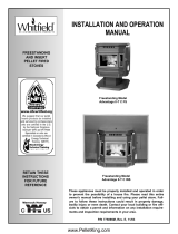
INSTALLATION AND OPERATION
MANUAL
Freestanding Model
Advantage
Optima 3 FS *
FREESTANDING
AND INSERT
PELLET FIRED
STOVES
These appliances must be properly installed and operated in order to
prevent the possibility of a house fire. Please read this entire owner's
manual before installing and using your pellet stove. Failure to follow
these instructions could result in property damage, bodily injury or even
death. Contact your local building or fire officials to obtain a permit and
information on any installation requirements and inspection require-
ments in your area.
P/N 775097M, Rev. E, 12/03
Insert Model, Advantage Optima 3 INS not shown
* Shown with Decorative Log Option
RETAIN THESE
INSTRUCTIONS
FOR FUTURE
REFERENCE
Freestanding Model
Advantage
Optima 2 FS *

IMPORTANT WARNINGS
CAUTION:
Read this manual thoroughly before starting installation. For your safety, follow the installation, op-
eration and maintenance instructions exactly without deviation. Failure to follow these instructions may result
in a possible fire hazard and will void the warranty. If this appliance is not properly installed, a house fire may
result. Contact local building or fire officials about requirements and installation inspection in your area.
PAGE 2
1. DO NOT CONNECT THIS UNIT TO A CHIMNEY
FLUE CONNECTED TO ANOTHER APPLIANCE.
2. Do not connect this appliance to air ducts or any air
distribution system.
3. Do not install a flue damper in the exhaust venting
system of this appliance.
4. Do not use class B venting intended for gas appli-
ances as a chimney or connector pipe on a pellet
fired appliance.
5. The minimum clearances must be maintained for all
combustible surfaces and materials including; fur-
niture, carpet, drapes, clothing, wood, papers, etc.
Do not store firewood within this clearance space.
6. INSTALLATION DISCLAIMER - This stoves exhaust
system works with negative combustion chamber
pressure and a slightly positive chimney pressure.
Therefore, it is imperative that the exhaust system
be gas tight and installed correctly. Since Lennox
Hearth Products has no control over the installa-
tion of your stove, Lennox Hearth Products grants
no warranty, implied or stated for the installation or
maintenance of your stove, and assumes no re-
sponsibility for any consequential damage(s).
7. Burning any kind of fuel consumes oxygen. If out-
side air is not ducted to the appliance, ensure that
there is an adequate source of fresh air available to
the room where the appliance is installed.
8. The stove will not operate using natural draft, nor
without a power source for the blower and fuel
feeding systems.
9. Never use gasoline, gasoline-type lantern fuel,
kerosene, charcoal lighter fluid, or similar liquids to
start or "freshen up" a fire in this heater. Keep all
such liquids well away from the heater while it is in
use.
10. CONTINUOUS OPERATION: When operated cor-
rectly, this appliance cannot be overfired. Continu-
ous operation at a maximum burn can, however,
shorten the life of the electrical components (blow-
ers, motors, and electronic controls), and is not
recommended. Typical approved operation would
include running at the low to mid range setting with
occasional running on the maximum setting during
the coldest periods of the winter. The blower speed
control should be turned to high when operating
the stove on the high heat setting.
11. CAUTION: NEVER PUT FINGERS NEAR AUGER.
Pellet fuel is fed to the UltraGrate by a screw auger.
This auger is driven by a high torque motor. The
auger is capable of doing serious harm to fingers.
Keep pellets in the hopper at all times and keep fin-
gers away from auger. The auger can start and
stop automatically at any time while the stove is
running.
12. CAUTION: HOT WHILE IN OPERATION. An appli-
ance hot enough to warm your home can severely
burn anyone touching it. Keep children, clothing
and furniture away. Contact may cause skin burns.
Do not let children touch the appliance. Train them
to stay a safe distance from the unit.
13. APPROVED FUEL: This appliance is designed
specifically for use only with pelletized wood fu-
els only. With its advanced UltraGrate technol-
ogy, this appliance is designed and approved for
the burning of wood residue pellets with up to 3%
ash content. This appliance is NOT approved to
burn cardboard, nut hulls, cherry pits, corn, etc.
regardless if it is in pellet form. Failure to comply
with this restriction will void all warranties and
the safety listing of the stove. Consult with your
authorized Lennox Hearth Products dealer for
more information on approved pellet fuels.
14. FLYASH BUILD-UP: For all wood pellet fuel-
burning heaters, the combustion gases will con-
tain small particles of fly ash. This will vary due to
the ash content of the fuel being burned. Over
time, the fly ash will collect in the exhaust venting
system and restrict the flow of the flue gases.
The exhaust venting system should be inspected
regularly and cleaned as necessary.
15. SOOT FORMATION: Incomplete combustion can
occur during startup, shutdown, or incorrect op-
eration of the room heater. This can lead to some
soot collecting in the exhaust venting system. A
precautionary inspection on a regular basis is
advisable to determine the necessity of cleaning.
The exhaust venting system should be inspected
regularly and cleaned as necessary.
16. DISPOSING OF ASHES: Any ashes removed
from the pellet stove must be deposited in a
metal container with a tight-fitting lid. The
closed container of ashes should be placed on
a noncombustible floor or on the ground, well
away from all combustible materials, outside of
the dwelling pending final disposal. If the
ashes are disposed of by burial in soil or oth-
erwise locally dispersed, they should be re-
tained in the closed container until all cinders
have been thoroughly cooled.
17. SAVE THESE INSTRUCTIONS.
18. See the listing label on the appliance (or see
Safety / Listing Labels on pages 51 and 52).

TABLE OF CONTENTS
PAGE 3
Important Warnings ................................................ 2
Testing / Listing, EPA, Using this Manual................ 3
Planning Your Installation ..................................... 4-9
Manufactured (Mobile) Home Installation ................9
Installation ........................................................ 10-21
Care and Operation .......................................... 22-27
Routine Maintenance........................................ 28-33
Specifications.................................................... 34-36
Definitions ...............................................................37
Wiring Diagram .......................................................38
Troubleshooting ................................................ 39-41
Replacement Parts List / Diagrams .................. 42-47
Optional Accessories ..............................................48
Installation Tips .......................................................49
Simple Operating Instructions.................................50
Safety / Listing Label and EPA Label ............... 51-52
Ownership Records ................................................53
LISTING / TESTING
Listing: The listing laboratory is ITS (Intertek Testing Ser-
vices) and the listing mark is Warnock Hersey.
Testing: In accordance with the specifications and proce-
dures listed in UL 1482 & ASTM E1509 for solid fuel room
heater, this appliance has been independently tested to UL,
ULC and CSA standards, report # 6658 for Advantage
Optima 2 and report #476-1244 for Advantage
Optima 3.
UL 1482 states requirements for installations as a free-
standing room heater, or hearth insert for masonry or listed
factory built (zero clearance) fireplaces. The safety-listing
label is located on an inside hopper surface of the pellet
stove. Please read this safety label carefully. It contains
important information about installation and operation of
this appliance. This appliance is tested and listed for resi-
dential installation according to current national and local
building codes as:
• A Freestanding Room Heater
• A Manufactured (mobile) Home Heater
EPA (Environmental Protection Agency)
Status: EPA Exempt - Pellet appliances that are de-
signed with the combustion air supply exceeding the 35
to 1 (by weight) ratio are exempt from EPA regulations
and are “non-affected facilities.”
PRODUCT IS SUBJECT TO CHANGE WITHOUT NO-
TICE.
CONGRATULATIONS ON THE PURCHASE OF YOUR
NEW PELLET STOVE MANUFACTURED BY LENNOX
HEARTH PRODUCTS.
When you purchased your new pellet stove, you
joined the ranks of thousands of concerned indi-
viduals whose answer to their home heating needs
reflects their concern for aesthetics, efficiency and
our environment. We extend our continued support
to help you achieve the maximum benefit and enjoy-
ment available from your new pellet stove.
It is our goal at Lennox Hearth Products to provide
you, our valued customer, with an appliance that will
ensure you years of trouble free warmth and pleas-
ure.
Thank you for selecting a Lennox Hearth Products
stove as the answer to your home heating needs.
Sincerely,
All of us at Lennox Hearth Products
PACKAGING LIST
The assembled pellet stove model Optima 2 FS, Optima 3
FS and Optima 3 INS are packaged with an accessory
package, which contains the following:
One - Installation and operation instructions manual.
One - Warranty.
One - Power cord.
One- Control board – Optima 3 INS only.
One - Screw, #8 x ½” tek (for mounting control board)
– Optima 3 INS only.
One - Grate scraper.
One - Video
One - Lower trim
One - Wall thermostat.
One - Roll of thermostat wire.
Two- Leveling bolts, ¼-20 x 3” – Optima
3 INS only.
One - Door Handle (removable)
One - Fireplace Warning Label (see page 8)
Surround Kit (For Optima 3 INS Only)
(Purchased separately, see page 48) kit is packaged with:
One - Top surround panel.
One - Left surround panel.
One - Right surround panel with door.
One - Left side trim.
One - Right side trim.
One - Top trim.
Two - Corner keys (“L” shaped surround trim brackets).
USING THIS MANUAL
Please read and carefully follow all of the instructions
found in this manual. Please pay special attention to the
safety instructions provided in this manual. The home-
owner’s Care and Operation Instructions included here
will assure you have many years of dependable and en-
joyable service from your appliance.

PLANNING YOUR INSTALLATION
PAGE 4
QUESTIONS TO ASK LOCAL BUILDING OFFICIAL
A correct installation is critical and imperative for reduc-
ing fire hazards and perilous conditions that can arise
when wood pellet burning appliances are improperly
installed. The installer must follow all of the manufac-
turers’ instructions.
The installation of this appliance must conform to local
codes and applicable state and federal requirements.
Familiarity with these requirements before installation is
essential. Important considerations to discuss with local
building officials include:
1. Applicable codes (i.e. Uniform Mechanical Code,
State or Regional Codes)?
Electrical codes:
In USA, NEC, ANSI / NFPA 70-2002.
In Canada, CSA C22.1
Power Supply Requirements
– The power cord
must be plugged into a standard, 115 volt, 60 Hz
grounded electrical outlet. The approximate
power requirement is 362 Watts, and will peak up
to 736 Watts for approximately 6 minutes when
the self-igniter is operating (it will turn off 2 min-
utes after flame detection). The power cord must
be routed to avoid contact with any of the hot or
sharp exterior surface areas of the stove. When
installed into a manufactured (mobile) home, the
appliance must be electrically grounded to the
steel chassis (see page 9, Manufactured [Mobile]
Home Requirements). These requirements must
be met unless otherwise specified by state or lo-
cal authorities.
WARNING: ELECTRICAL GROUNDING IN-
STRUCTIONS: THIS APPLIANCE IS
EQUIPPED WITH A THREE-PRONG
(GROUNDING) PLUG FOR YOUR PROTEC-
TION AGAINST SHOCK HAZARD AND
SHOULD BE PLUGGED DIRECTLY INTO A
PROPERLY GROUNDED THREE-PRONG
RECEPTACLE. DO NOT CUT OR REMOVE
THE GROUNDING PRONG FROM THIS
PLUG. DO NOT ROUTE POWER CORD UN-
DER OR IN FRONT OF APPLIANCE.
2. Local amendments?
3. Is a permit required - cost?
(you may wish to contact your insurance com-
pany to ask if they require this).
4. Is outside combustion air required?
5. Rooms where the installation is not allowed?
INSTALLATION / MAINTENANCE STANDARDS
National Fire Protection Association – The primary
NFPA standard that refers to installation and mainte-
nance of pellet appliances and venting is NFPA 211:
Chimneys, Fireplaces, Vents, and Solid Fuel appli-
ances, Jan. 2000.
SELECTING A LOCATION
The design of your home and where you place your
stove will determine its value as a source of heat. This
type of appliance depends primarily on air circulation
(convection) to disperse its heat, and therefore, a cen-
tral location is often best. There are other practical con-
siderations, which must be considered before a final
selection of locations is made.
♦ Existing Chimneys
♦ Pellet Fuel Storage
♦ Aesthetic Considerations
♦ Roof Design (rafter locations & roof pitch)
♦ Room Traffic
♦ Proximity to Combustibles
♦ Electrical Wiring
The installation of this stove will require some research.
Once your options are determined, consult with your
local building department who will be able to give you
the necessary installation requirements for your area (Is
a building permit required? Rooms where installation
may not be allowed, etc.).
WARNING: CHECK ALL LOCAL BUILDING AND
SAFETY CODES BEFORE INSTALLATION. THE IN-
STALLATION INSTRUCTIONS AND APPROPRIATE
CODE REQUIREMENTS MUST BE FOLLOWED EX-
ACTLY AND WITHOUT COMPROMISE. ALTERA-
TIONS TO THE STOVE ARE NOT ALLOWED. DO
NOT CONNECT THE STOVE TO A CHIMNEY SYS-
TEM SERVING ANOTHER STOVE, APPLIANCE, OR
ANY AIR DISTRIBUTION DUCT. FAILURE TO FOL-
LOW THESE INSTRUCTIONS WILL VOID THE
MANUFACTURERS WARRANTY.
SMOKE DETECTORS
Since there are always several potential sources of fire
in any home, we recommend installing smoke detec-
tors. If possible, install the smoke detector in a hallway
adjacent to the room (to reduce the possibility of occa-
sional false activation from the heat produced by the
stove). If your local code requires a smoke detector be
installed within the same room, you must follow the re-
quirements of your local code. Check with your local
building department for requirements in your area.

PLANNING YOUR INSTALLATION
PAGE 5
FLOOR PROTECTION - Optima 2 FS
This appliance requires noncombustible floor protec-
tion. If the floor protection is to be stone, tile, brick, etc.,
it must be mortared or grouted to form a continuous
non-combustible surface. If a chimney connector ex-
tends horizontally over the floor, the protection must
cover the floor under the connector and at least 2" to
either side.
A noncombustible floor protector must fully cover the
area beneath the appliance and extend 6” to the front,
6” to the sides, and up to 6" from the back as illus-
trated on this page.
*Note: When installed at clearances less than 6”, floor pro-
tection is only required to extend to the wall.
Top View of Model: Optima 2 FS
Up to * 6"/153mm
minimum
6"/
153mm
min..
6"/
153mm
min.
Rear
Front
6"/
153mm
min.

PLANNING YOUR INSTALLATION
PAGE 6
FLOOR PROTECTION - Optima 3 FS
The floor protector must
meet or exceed the
minimum thermal re-
quirements as defined
on this page (see Floor
Protection/Hearth Ex-
tension Using Alternate
Material As Floor Pro-
tector). If the floor pro-
tection is to be stone,
tile, brick, etc., it must
be mortared or grouted
to form a continuous
noncombustible sur-
face. If a chimney con-
nector extends horizon-
tally over the floor, pro-
tection must also cover
the floor under the connector and at least 2" (51 mm) to either
side.
The floor protector must fully cover the area beneath the appli-
ance and extend 6” to the front, 6” to the sides, and 6” from the
back as shown in the illustration to the right (Note: When installed
at clearances less than 6”, the floor protection is only required to
extend to the wall).
FLOOR PROTECTION / HEARTH EXTENSION USING
ALTERNATE MATERIAL AS FLOOR PROTECTOR
(also
see Floor Protection above for freestanding models and
Hearth Requirements, page 8 for the insert model)
The hearth pad or alternate material used as a floor/hearth
protector must be constructed of a durable noncombustible
material having an equal or better thermal conductivity value
(lower k value) of k = .84 BTU / IN FT
2
HR °F or a thermal
resistance that equals or exceeds r = 1.19 HR °F FT
2
IN/BTU
with a minimum thickness of 3/8”. With these values, deter-
mine the minimum thickness of the alternate material required
using the formula(s) and the table shown here (see chart -
Approved Alternate Materials for Floor/Hearth Protection).
Note: Any noncombustible material having a minimum thickness
of 3/8” (10 mm) whose k value is less than .84 or whose r value
is more than 1.19 is acceptable. If the alternate material used has
a higher k value or lower r value will require a greater thickness of
the material used. In some cases, if the k value is less or the r
value higher, a thinner material may be used.
Methods of determining floor protection equivalents:
To determine the thickness required for the alternate material
when either the k value or r value is known, use either the k
formula or r formula:
Example: Durock Cement
is to be used for the floor protec-
tion. How thick must this material be? The following formulas
give the means of determining minimum thickness required.
T
M
= minimum thickness required for alternate material
k
M
= k value per inch of alternate material
T
L
= minimum thickness of listed material
r
M
= r value per inch of alternate material
Using the k formula
:
Minimum k-value (per Inch) Specified min.
thickness of = of alternate material
x thickness
alternate k-value (per inch) of listed
material of listed material material
T
M
(inches) = k
M
x T
L
.84
T
M
(inches) = 1.92 x .375 (3/8”)
.84
Answer using k: 2.29 x 0.375” = 0.858 = ~7/8”
7/8” thickness (minimum) Durock Cement will be required.
Using the r formula
:
T
M
(inches) = 1.19 x T
L
r
M
T
M
(inches) = 1.19 x 375 (3/8”)
.52
Answer using r: 2.29 x 0. 375” = 0.858 = ~7/8”
7/8” thickness (minimum) Durock Cement will be required.
At times it is important to know what combination of materials
are acceptable for use as floor protection. The “R values” are
used to determine acceptable combinations of materials be-
cause “R values” are additive where r and k values are not.
“R value” = 1
= r x thickness of material used
k
Example: Given that the required “R value” for a suitable floor
protector used must be equal to or greater than “R” = r x T
L
=
1.19 x .375” = .45.
Approved Alternate Materials for
Floor/Hearth Protection (**)
Alternative
Materials ↓
Thermal Values * Minimum
Thickness
k (per inch) r (per inch) T
M
Kaowool M Board .47 2.13 * 3/8”
Micore 160
.35 2.86 * 3/8”
Micore 300
.46 2.18 * 3/8”
Durock Cement
1.92 .52 7/8”
Hardibacker
1.95 .51 7/8”
Hardibacker 500
2.30 .44 1 1/8”
Cultered Stone
Hearthstone
2.82 .35 1 5/8”
Wonderboard 3.23 0.31 1 1/2”
Face brick 9.00 0.11 4 1/8”
Common brick 5.00 0.20
2 1/4”
Cement mortar 5.00 0.20 2 1/4”
Ceramic tile 12.5 .08
5 5/8”
Marble
~20.0 ~.05
9”
Note: To convert inches to millimeters divide by .03937.
* After minimum thickness is calculated, the thickness can be
no less than 3/8” (.375” / 10mm).
(**) If the floor protector to be used is a noncombustible material
and is NOT listed on the chart above, the manufacturer of the ma-
terial must provide either the listed k-value per inch or r-value per
inch and the minimum acceptable thickness will need to be calcu-
lated per instructions on this page.
.
Top View
*Up to 6”
1 53 mm minimum
6”/
153mm
min.
6”/
153mm
min.
6”/153mm
minimum
Listed Material
Thermal Values
Specified
Minimum
Thickness
k (per inch) r (per inch) T
L
Listed Material →
.84 1.19 3/8” (.375)

PLANNING YOUR INSTALLATION
Clearances to combustibles are determined from testing to applicable standards for allow-
able heat transfer. The clearances allowed as shown here, do not take into account opera-
tion or serviceability requirements.
PAGE 7
CLEARANCES
Optima
2 FS and Optima 3 FS - Standard residential or
manufactured (mobile) home installation. These appli-
ances require the following minimum clearances to com-
bustibles:
MINIMUM CLEARANCES TO COMBUSTIBLES
Manufactured (Mobile) Home
or Residential Installation
Horizontal Flue – Di-
rectly Through Wall
Interior Vertical Flue
Optima 2 FS
Clearance to
Combustibles
inch / millimeter inch / millimeter
A - Sidewall to unit ♦4” / 102 mm ♦4” / 102 mm
B – Backwall to unit *2” / 51 mm 9” / 229 mm
C – Sidewall to unit
Corner
*2” / 51 mm *2” / 51 mm
D – Max. Depth of
Alcove
•24” / 610 mm •24” / 610 mm
E – Flue to Wall 3” / 77 mm 3” / 77 mm
♦ Measured to fuel hopper lid in alcove.
• Minimum Alcove Measurements - Height 48” / 1220 mm
Width 31” / 788 mm
Manufactured (Mobile) Home
or Residential Installation
Horizontal Flue – Di-
rectly Through Wall
Interior Vertical Flue
Optima
3 FS
▪ Clearance to
Combustibles
inch / millimeter inch / millimeter
A - Sidewall to unit ♦6” / 153 mm ♦6” / 153 mm
B – Backwall to unit *2” / 51 mm 9” / 229 mm
C – Sidewall to unit
Corner
*2” / 51 mm *2” / 51 mm
D – Max. Depth of
Alcove
•16” / 407 mm •16” / 407 mm
E – Flue to Wall 3” / 77 mm 3” / 77 mm
♦ Measured to fuel hopper in alcove.
• Minimum alcove measurements - Height 48” / 1220 mm
Width 38” / 966 mm
Minimum clearances specified may not allow for
ease of operation and maintenance (please take
this in to account when planning the installation).
If installed to the minimum clearances, removal of
the appliance may be necessary for servicing.
Recommended clearance zone from the front of
the appliance to combustibles is 4 feet minimum.
* The certified back wall clearance as shown on the
listing label is 1" (see Safety / Listing Label) but for
proper hopper lid operation in corner and parallel
installations a 2" clearance is required.
Rear Wall or Alcove – Optima
2 FS and Optima 3 FS
Corner - Optima 2 FS
Corner - Optima 3 FS
*
*
*
*
*

PLANNING YOUR INSTALLATION
PAGE 8
MASONRY AND FACTORY BUILT FIREPLACES
The model Optima
3 INS is approved for installation into a solid
fuel burning fireplace, either a masonry fireplace (built to UBC 37
or ULC S628 standards) or an approved factory-built / zero
clearance fireplace (built to UL 127 or ULC S610 standards).
See pages 20 and 21 for additional information on venting.
Minimum Fireplace Firebox Size
Height 20 1/8” / 512 mm
Width @ Front 32” / 814 mm
(extends back 1 ½”)
Width @ back 24 5/8” / 626mm
Depth 17 ¾” / 452 mm
CAUTION: The fireplace in which the Optima 3 INS is to be
installed must be thoroughly cleaned if it has been used to burn
wood or synthetic logs. Have the chimney and all inside sur-
faces of the fireplace brushed and vacuumed so that no soot,
embers, or loose combustion deposits can be drawn into the
heat circulation blower and blown into the living area. If any por-
tion of the chimney system shows signs of structural or me-
chanical weaknesses, such as: cracks, leaky joints, corroded or
warped surfaces, the faulty portion must be repaired or replaced
prior to installing this appliance.
IMPORTANT: When installing the Optima 3 INS into a factory
built fireplace or heatform, the air flow within and around the fire-
place shall not be altered by the installation of the insert (i.e. DO
NOT BLOCK louvers or cooling air inlet or outlet ports, circulating
air chambers in a steel fireplace liner or metal heat circulator). The
factory built firebox must accept the insert without modification
other than removing bolted or screwed together pieces such as
smoke shelf / deflectors, ash lips, screen or door tracks and
damper assemblies. Any fireplace component, which is removed,
must be retained so they can be reinstalled to restore the fireplace
to its original operating condition. The removal of any part must
not alter the integrity of the outer shell of the pre-engineered fire-
place cabinet in any way. A Warning Label (provided with appli-
ance) must be installed in the fireplace firebox so that it shall be
visible upon removal of the fireplace insert (see Fireplace Warning
Label, below). Use RTV high Temperature Silicone as an adhe-
sive to affix the warning label.
Fireplace Warning Label
(provided in accessory package)
THIS FIREPLACE HAS BEEN ALTERED TO ACCOMMO-
DATE A FIREPLACE INSERT AND SHOULD BE IN-
SPECTED BY A QUALIFIED PERSON PRIOR TO RE-
USE AS A CONVENTIONAL FIREPLACE.
HEARTH / FLOOR PROTECTION - Optima 3 INS
The area directly in front of the Optima 3 INS
must be protected by a noncombustible material
or a fireplace hearth or hearth extension as fol-
lows:
Combustible flooring must be protected by
non-combustible material in Canada and 10
millimeter (3 / 8 inches) millboard or equivalent
non-combustible in U.S. extending beneath the
heater and to the front as indicated or to the
nearest permitted combustible material. See
page 6 for requirements when using alternate
material as hearth extension.
The protected area must extend 6” to the front of
the face of the Optima 3 INS.
MINIMUM CLEARANCES TO COMBUSTIBLES
inches / millimeters
A - Insert to side wall 6” / 153 mm
B - Insert to side trim 1” / 26 mm
C - Hearth extension 6” / 153 mm
D - Insert to mantel 18” / 458 mm
E - Insert to top trim 1” / 26 mm
Top View
Side View
Recommended clear-
ance zone from the
front of the appliance
to combustibles is 4
feet minimum.
24 5/8"
17 3/4
"
32"
Clean-out
Tee
D
E
Mantel
Trim
Side Wall Trim

PLANNING YOUR INSTALLATION
PAGE 9
Models – Optima 2 FS and Optima 3 FS
MANUFACTURED (MOBILE) HOME INSTALLATION
Freestanding Models – Optima 2 FS and Optima 3 FS
In addition to the standard installation instructions, the
following instructions may be required by local, state or
federal building codes:
• Stove must be permanently bolted to the floor.
• An outside air inlet must be provided for combustion
and be unrestricted while unit is in use. Use a galva-
nized or stainless steel pipe for the duct (the outside
air inlet on the stove is 2" diameter).
• Stove must be permanently electrically grounded to
the steel chassis of the home. The location selected
for ground attachment to the stove must be dedicated
for this purpose.
• See pages 14 through 19 for additional information on
venting requirements.
• Do not install appliance in a sleeping room.
• The structural integrity of the manufactured home
floor, walls, ceiling and roof must be maintained.
NOTE: The grounding of this product, at installation,
must comply with NFPA-70 standards, CSA C22.1 in
Canada, as well as any local codes.
MANUFACTURED (MOBILE) HOME EXHAUST VENT
PIPE INSTALLATION GUIDELINES
Use only listed type “PL” pellet vent pipe. Pipe should
extend at least 3 feet above the part of the roof through
which it passes. The top of the pipe should be at least 2
feet above the highest required elevation of any part of
the manufactured (mobile) home within 10 feet of the
pipe.
If the exhaust vent exits the manufactured (mobile)
home at a location other than the roof, and exits at a
point 7 feet or less above the ground level on which the
manufactured (mobile) home is positioned. A guard or
method of enclosing the pipe shall be provided at the
point of exit for a height of up to 7 feet. The openings, if
any, in this guard shall not allow a 3/4” rod to pass
through. A 1/2” rod could pass through but should not
be able to touch the pipe when inserted through the
opening a distance of 4 inches.
Bolt
Floor Protector
Floor
Cha
s
sis
Ground to Steel Chassis

INSTALLATION
PAGE 10
REMOVING APPLIANCE FROM PALLET
1. After removing the packaging from the stove, lift the hop-
per lid, and remove all pre-packaged items that were
shipped in the hopper. Next, open the stove door and
remove all pre-packaged items.
2. Using a socket or open end wrench (7/16" for freestand-
ing units and 3/8" for the insert), remove the pallet bolts
which secure the unit to the pallet (located on each side
of back corners and at the front under ash pan). See fol-
lowing pictures.
Optima 3 INS
Side View of Optima 2 FS & Optima 3 FS
(Removing Back Pallet Bolts)
Note: The pallet bolt at the front of appliance is located un-
der the ash pan (this will require removing the ash pan. See
Ash Pan on pages 28 and 29 for removal instructions). See
following picture (freestanding unit shown).
Front View - Removing Front Pallet Bolt
INSTALLATION CHECK LIST
It is strongly recommended that you have an author-
ized Lennox Hearth Products dealer install your
stove. If you install your stove yourself, you should
review your installation plan with an authorized Len-
nox Hearth Products dealer.
Check list:
Check off each item as you proceed with the installa-
tion process.
Read the ENTIRE stove installation section first
Read the Insert or Freestanding section (which-
ever applies).
Determine the appropriate measurements and
locations for your installation.
Follow the general installation directions under
Stove Installation and the installation section ap-
propriate to your stove.
Be sure to pre-fit all items before you install, fas-
ten, or set up the stove permanently.
Prior to lighting your stove:
Review the Important Warnings section (page 2).
Review Fuel Specifications (page 27).
Review and follow instructions in the Care and
Operation Section (pages 22 to 27).
Plug power cord connector into corresponding
connector on the back of appliance (see illustra-
tions on page 13 showing connector locations).
Note
: Optima 3 INS – Route power cord behind
side surround panel.
After you have begun operation of your stove:
Review the routine cleaning / maintenance informa-
tion.
Enjoy the warmth from your new Lennox Hearth
Products pellet stove!
(Insert Only) It is important to level the appliance. In
some installations such as a recessed firebox floor (if
the existing fireplace floor is lower than the hearth),
install the 2 leveling bolts (1/4-20 x 3” long) into the
threaded holes at the rear base of the Optima 3 INS.
Adjust bolts until appliance is level.
Use a 3/8" nut
driver to remove
the bolts on
both brackets
(located on each
side of the in-
sert back
)
.
Remove 1
bolt on each
side of stove
back
With the ash pan
removed, remove
center bolt.
Stove or Insert Front

INSTALLATION
PAGE 11
INSTALLING SURROUND ASSEMBLY - Optima 3 INS
(to be done after venting system is installed)
The surround kit (purchased separately) comes with a
set of metal panels that enclose the fireplace opening
when fitted together. There is also a trim assembly that
frames the surround assembly to give it an attractive fin-
ished appearance. Put the surround assembly together
according to the following instructions.
1. Remove panels from package.
2. Open the hopper lid on Optima 3 INS so it is out of
the way for when panels are installed.
3. Install the control board onto the right side panel (with
door) using the TEK screw (#8 x ½”) provided.
4. Position the power cord so that it will be behind either
the right or left side surround panel when they are in-
stalled.
5. Install right side surround panel onto right side of the
Optima 3 INS body by sliding the 2 flanges on side of
panel into corresponding slots on the Optima 3 INS.
6. Connect the wiring harness from the Optima 3 INS
into corresponding connector on control board.
Locate damper rod on left side of the Optima 3 INS. Ro-
tate angled arm of rod so it is pointing down. Remove
damper knob and set aside.
7. Install the left-hand panel onto the left side of Optima
3 INS body by sliding the 2 flanges on side of panel
into corresponding slots on the Optima 3 INS.
8. Reach behind left surround panel and rotate damper
arm so that end is inserted into the upper right hand
slot of left surround panel (see illustration on page 12,
Optima 3 INS).
9. Reinstall damper knob by threading it onto end of
damper rod.
10. Set the top surround panel in place over the two side
panels. Position the 2 tabs on bottom of top surround
panel so they slide into corresponding clips on the
Optima 3 INS. Connect the top surround panel to the
side panels by pressing pins from side panels into
corresponding holes on top panel.
11. Remove the surround trim from its packaging. As-
semble it together using the corner keys (“L” shaped
brackets) provided. Slide assembled trim over the top
surround panel and slide it down over the side pan-
els.
12. Push the Optima 3 INS back into place so the sur-
round is flush with the face of the hearth.

INSTALLATION
PAGE 12
Optima 3 INS (Only) – Install damper rod knob as ex-
plained on page 11.
Adjustment Procedure:
The damper knob should be
positioned in the center of the oblong slot for the aver-
age installation (see illustration above). If more or less
air is needed, then adjust in ¼" increments until opti-
mum combustion air flow is achieved (see Damper Ad-
justment Guidelines on page 26).
Damper Locations
See ‘Opening Side Panels’, page 33 for instructions on
opening the side panels for models Optima 2 FS & Op-
tima 3 FS. See ‘Installing Surround Assembly’ for in-
structions on side surround panel access for model Op-
tima 3 INS.
Optima 2 FS - The damper control handle is located on the
right-hand side panel.
Optima 3 FS - The damper control handle is located on the
left-hand side panel.
Optima 3 INS - The damper control handle is located on the
left surround panel.
Damper Adjustment
It is very important to preset your damper prior to burn-
ing your pellet stove.
Damper - Air Control Handle – Freestanding Units
Adjustment Procedure:
Loosen setscrew on set collar
(see above picture), then adjust in ¼" increments until
optimum combustion air flow is achieved. For less air
push in and for more air pull out. After adjustment, posi-
tion set collar against side panel and tighten setscrew.
Damper is factory set to a gap as
specified below. Follow Dampe
r
Adjustment Guidelines on page 26.
To adjust, use a
3/32" allen wrench
to loosen set collar.
1 5/8" – Optima 3 FS
1 1/2" – Optima 2 FS
Damper
Knob
Left
Surround
Panel
More Air
Less Air
For less air, slide
damper knob to the
right (or) for more air,
slide knob to the left.

INSTALLATION
THERMOSTAT INSTALLATION:
NOTE: Always Disconnect Power Before Performing The Thermostat Installation
.
A 24 volt wall thermostat and 20 feet of 18-gage thermostat wire is included in your stoves accessory package. It is rec-
ommended that the thermostat and thermostat wire be installed by an authorized Lennox Hearth Products dealer.
Installation Steps:
1. Unplug stove power cord from the wall outlet.
2. Locate the thermostat terminal block (see illustrations below).
3. Loosen the two terminal screws on the terminal block and remove the jumper.
4. Connect the two wires from your thermostat to the terminals (one per terminal). Ensure that the purple wires from the
harness remain connected to the terminal block and tighten the terminal screws. Make sure the wires are firmly con-
nected to the thermostat.
5. Plug in the stove and you are ready to operate with your thermostat!
IMPORTANT: IF THE WALL THERMOSTAT PROVIDED IS NOT USED, THE JUMPER IS REQUIRED FOR THE
STOVE TO OPERATE.
PAGE 13
Terminal Block for Thermostat
Leave Jumper on, If Thermostat Is Not
Used
Remove Jumper if Thermostat Is
To Be Used
Model: Optima 3 FS
Model: Optima 3 INS
(on right side of insert when viewed from the front)
Th
Model: Optima 2 FS
(viewed from stove back)
Jumper
Terminal Block
for Thermostat
Terminal Block
for Thermostat
Terminal Block
for Thermostat
Power Cord
Connector
Power Cord
Connector
Power Cord
Connector

INSTALLTION
PAGE 14
VENTING REQUIREMENTS
It is recommended that only an authorized dealer install
your pellet stove. The specified installation requirements
must be followed to ensure conformity with both the
safety listing of the appliance and local building codes. All
clearances, installation instructions and precautions
specified by the vent manufacturer must be followed.
Selecting a Location (Freestanding Models)- Review
the appliance clearance requirements before installing
the venting system (see page 7). Position the appliance
far enough away from walls to allow adequate room for
servicing. Choose the appliance location with the least
amount of interference with the house framing, plumbing,
wiring, etc.
Preferred Vent Configuration – For the best perform-
ance, we recommend a vent run design which runs verti-
cally and terminates above the roofline. This design will
allow natural draft to improve the flow of flue gases and
will aid in combustion and stove performance.
Type of Pipe - This stove requires type “PL” (pellet vent
pipe, sometimes referred to as “L-Vent pellet vent”),
which conforms to UL standard 641. Connect the pellet
vent pipe or the “tee” to the flue collar using a minimum of
three screws and seal as specified in “Pipe / Liner Joint
Requirements” on this page. Do not use class B gas chim-
ney or single wall chimney as a substitute.
Size of Pipe -These pellet appliances are approved for
use with the following vent sizes: 3” (75mm) standard, or
4” (100mm). See page 16 for determining correct size
vent to use. Use a 3” (75mm) to 4” (100mm) adapter
(Cat. No. 14M81) or a 3” (75mm) to 4” (100mm) “tee” in
order to run 4” (100mm) pipe.
Offsets - In every installation, a single or double clean-
out “tee” is recommended for every ninety-degree offset
(this tee will help collect ash residue and will allow for
routine cleaning without the need to disconnect sections
of pipe).
Note: Offsets and horizontal runs accumulate fly ash and
soot which reduces the exhaust flow and performance of
the stove.
Total Offsets in venting system should not exceed 270°
total in direction change.
Horizontal Runs - The maximum total horizontal run
must not exceed 10 feet (3.1 meters).
Horizontal run of pipe requires 1/4” / 7 mm rise per foot.
Pipe Clearances / Requirements – See pipe manufac-
turers instructions for installation of venting components
and clearances. Follow pipe manufacturers installation
precautions for passing pipe through a combustible wall
or ceiling (i.e. use an approved thimble).
Notes:
All pellet vent pipe requires 3” (75mm) clearance from
outside of pipe unless otherwise specified by vent manu-
facturer.
A support bracket should be installed every 4’ (1.2m) of
pellet vent pipe on the exterior wall of the house unless
otherwise specified by vent manufacturer.
Pipe / Liner Joint Requirements - All pipe joints must
be secured with a minimum of 3 screws. ALL horizontal
joints must be sealed gas tight (air tight, sealed connec-
tion). Use High Temperature RTV silicone with a rating of
at least 570° F (969° C), or Interam to provide a complete
seal at the flue collar and on all joints.
Connection to Masonry Chimney through a Wall
(Freestanding Models) - Be sure to verify the construc-
tion of a masonry chimney, as it may have combustible
framing.
Approved liner when relining Masonry or Factory
Built Fireplaces is 2100HT (degree F.) liner listed to
UL 1777 or ULC S635.
Connection to an Existing Class A Chimney (Free-
standing Models) - A chimney adapter can be used to
make the connection from 3” / 75mm or 4” / 100mm pellet
vent pipe to existing UL chimney system. Verify with the
pipe manufacturer that your pipe brands will interconnect.
Horizontal-Vent Installations - On all horizontal-vent
installations (short, horizontal runs with no vertical pipe);
care should be taken when choosing a location for termi-
nating the vent. It is not recommended to directly vent the
exhaust on the prevailing wind side of the house. It is
recommended that when an appliance is vented directly
through a wall, a minimum of 8’ (2.5m) of vertical pipe
should be installed to create some natural draft. This will
reduce the possibility of smoke or odor entering the
dwelling during appliance shutdown or loss of power.

INSTALLTION
PAGE 15
VENT TERMINATION
Do not terminate vent in an enclosed or semi-enclosed
area such as: carports, garage, attic, crawl space, under
a deck, porch, narrow walkway, closely fenced area, or
any location that can build up a concentration of fumes
such as a stairwell, covered breezeway etc.
Vent surfaces can get hot enough to cause burns if
touched. Adults should supervise children when they are
in the area of a hot stove. Non-combustible shielding or
guards may be required.
Termination Cap: The termination of the outside chim-
ney of the pellet stove shall be located in accordance with
the following:
A. Higher than 3’ (.92m) above any forced air inlet (air
conditioner, etc.) located within 10’ (3m).
B. Not less than 4’ (1.2m) below, 4’ (1.2m) horizontally
from or 1’ (3.1m) above any gravity air inlet (door, win-
dow, etc.) which flue gases could re-enter the dwelling.
C. Not less than 2’ (.6m) from combustible materials such
as an adjacent buildings, fences, protruding parts of the
structure, roof overhang, plants and shrubs, etc. and
not less than 7’ (2.1m) above grade when located adja-
cent to the public sidewalks (access). The final termina-
tion of the exhaust system must be configured so that
flue gases do not jeopardize the safety of people pass-
ing by, overheat combustible portions of nearby struc-
tures or enter the dwelling.
D. Not less than 3’ (.92m) below an eave (maximum
overhang of 3’ (.92m) or any construction that pro-
jects more than 2” (51mm) from the plane of the wall.
E. The distance from the bottom of termination to grade
is 12” (305mm) minimum. This is conditional upon
plants and nature of grade surface: Be careful to
choose a location for the vent termination, which
does not expose people or shrubs to high heat from
the exhaust gases. The exhaust gases are not hot
enough to ignite grass, plants and shrubs located in
the vicinity of the termination although they should be
a minimum of 3’ (.92m) away. The grade surface un-
der the termination must not be a lawn.
F. Since sparks may escape from the exhaust pipe of
any stove, use caution when positioning the vent
pipe. Refer to pipe manufacturer’s instructions when
installing and terminating the exhaust. The vent pipe
should be horizontal and never run the pipe in a
downward direction (recommend a ¼” (7mm) rise
per foot horizontal).
Notes:
• It is not recommended to terminate exhaust vent on the
prevailing wind side of the house.
• It is not recommended using a termination cap with a
screen (fly ash can collect in a screen resulting in
blockage).
Site Built Residential Home
Chimney Height Requirements
The vent termination height required is - USA, 1-foot
minimum; Canada 3-feet minimum above the roof pene-
tration point as illustrated below (Ref. USA - National
Standard, NFPA 211, Clause 7-4.1 and Canada National
Standard CSA B365-01, Clause 5.6). Check with your
local building official for additional requirements for your
area.
Manufactured (Mobile) Home
Chimney Height Requirements
The chimney must extend 3’ (.92m) above the level of
roof penetration and a minimum of 2’ (.61m) higher than
any roof surface within 10’ (3m) (see below). Check with
your local building officials for additional requirements for
your area.
To pass inspection in nearly any jurisdiction, the chimney
must meet both safety and exhaust flow requirements.
The (3’ by) 2’ by 10’ rule applies to both masonry and
factory built chimneys.
* Ref. NFPA 211 Clause 7 – 4.1.2, Vents installed with a
listed cap shall terminate in accordance with the terms
of the cap’s listings.
REQUIRES A LISTED
TERMINATI
O
N
C
AP *
TOP OF FLUE MUST BE 2’
HIGHER THAN ANY PART OF
ROOF WITHIN 10’ HORIZONTAL
TOP OF FLUE MUST BE 3’ HIGHER THAN
HI
G
HE
S
T P
O
INT
O
F R
OO
F PENETRATI
O
N
TERMINATION
CAP MUST BE
LISTED TO UL
641 AND ULC
S609 *
TERMINATION HEIGHT IS
MEASURED ABOVE THE
HIGHEST POINT WHERE
IT PASSES THROUGH
THE ROOF SURFACE.
USA 1 Foot Minimum
CANADA 3 Feet Minimum

INSTALLATION
PAGE 16
DETERMINING SIZE OF PIPE TO INSTALL
To determine what diameter pipe to use in an installation (3” or 4”), first find the “equivalent pipe length” using the follow-
ing guidelines, then plot this figure and the altitude on the chart.
Fill out the installation chart, and calculate your total equivalent pipe length. After you have the total equivalent pipe
length, use the Pipe Selection Chart below to determine if your installation requires 3” or 4” exhaust pipe
.
INSTALLATION CHART
Type of
Pipe
# of Elbows
or Feet of
pipe
Equivalent
Feet
Total
Equivalent
Feet
90
o
Elbows /
Tee (A & G)
x 5 Ft. (1.5m)
45
o
Elbows (C)
x 3 Ft. (1m)
Horizontal
(B & F)
x 1 Ft. (.3m)
Vertical
(E)
x .5 Ft.
(.15m)
A- 90 Degree Elbow E- 8’ Vertical Pipe
B- 1’ Horizontal Pipe F- 2’ Horizontal Pipe
C- 45 Degree Elbow G- 90 Degree Tee
D- Standoff Braces
H- Wall Thimble
NOTE: All equivalent pipe styles shown to the right are
standard for all freestanding models.
SAMPLE INSTALLATION CHART
Type of
Pipe
# of Elbows
or Feet of
pipe
Equivalent
Feet
Total
Equivalent
Feet
90
o
Elbows /
Tee (A & G)
2 x 5 Ft. (1.5m) 10 (3m)
45
o
Elbows (C)
1 x 3 Ft. (1m) 3 (1m)
Horizontal
(B & F)
3 x 1 Ft. (.3m) 3 (1m)
Vertical
(E)
8 x .5 Ft. (.15m) 4 (1.2m)
Total = 20
PIPE SELECTION CHART
0 1 2 3 4 5 6 7 8 9 10
Altitude x 1000 Feet
4 “ Diameter Only
3 or 4”
Diamete
r
30
20
10
0
Equivalent Pipe Length (Feet)

INSTALLATION
PAGE 17
INSTALLING YOUR FREESTANDING PELLET STOVE
Standard Horizontal Vent Installation
1. Locate the proper position for the listed type “PL”
wall thimble. Avoid cutting wall studs when installing
your pipe. Use a saber saw or keyhole saw to cut
the proper diameter hole through the wall to accom-
modate the wall thimble. Use extreme caution to
avoid cutting into power lines within the wall of the
home. The hole size will depend on the brand of
pellet vent that you are using. Install the wall thimble
in the hole.
ALL INTERLOCKING PIPE CONNECTIONS WITH-
IN THE ROOM MUST BE SEALED WITH High Tem-
perature RTV AND SECURED WITH A MINIMUM
OF 3 FASTENERS PER CONNECTION.
2. Position the stove approximately 12” (.3m) from the
wall on the floor pad. Push listed type “PL” pipe
through wall thimble. Squeeze a bead of high tem-
perature silicone (High Temperature RTV) sealer
around the end of the machined portion of the 3”
(76mm) pipe connector on the back of the stove.
Firmly push on a section of listed type “PL” pipe until
inner pipe liner pushes into the bead of High Tem-
perature RTV sealer.
3. Push the stove (with pipe attached) towards wall.
Pipe will go through the wall thimble. Do not position
the back of the stove closer than 2” (51mm) from the
wall.
NOTE: Greater back clearance will improve the ser-
viceability of the stove.
4. Install listed type “PL” 45 degree elbow with optional
rodent screen or cap (recommended) on outside end
of pipe. The rodent screen should be no less than
1/2” (13 mm) mesh and may clog with soot and ash
if left unattended during the burn season.
NOTE: The end of the exhaust pipe must extend a
minimum of 12” (.3m) from the outside of the build-
ing.
5. If the installation includes a source of outside com-
bustion air; cut a separate hole through the wall for
the fresh air tube. Use a galvanized or stainless
steel pipe for the duct. The minimum size for the
duct shall be not less than 50% of the cross sec-
tional flue area. Connect outside air pipe to air inlet
on stove. This tube must be terminated with a 45
degree elbow or hood.
NOTES:
Combustion air may also be drawn from a vented crawl
space under the home.
All joints for connector pipe are required to be fastened
with at least three screws. If vented horizontally, joints
shall be made gas-tight (air tight, sealed connection) in
a manner as specified on this page (see instruction #1).
Install vent at clearances specified by the vent manu-
facturer.
Quick
Disconnect
Back of
Stove
Exhaust
Port
Gasket
Inlet
Air
Port
Straight PL-Vent
Pipe
Wall Thimble 45 Degree
Elbow
45 Degree Elbow Joint
for Fresh Air Pipe
Holes Through the Wall for the
Thimble and Fresh Air Pipe

INSTALLATION
Standard Horizontal Installation Configurations
Note: Horizontal run of pipe requires 1/4” (7 mm) rise per foot.
PAGE 18
Optima 3 FS
Corner Through the Wall
Optima
2 FS and Optima
3 FS
Horizontal Vent Through the Wall
3” (75 mm) Mini-
mum clearance be-
tween wall and pipe.
If you vent to the
furthest wall, the
vent pipe must
maintain a 3” clear-
ance parallel to the
other wall.
Wall
Wall
Wall
Wall
Top View Illustration
Top View Illustration
3” (75 mm) Minimum
clearance between
wall and pipe. If you
vent to the furthest
wall, the vent pipe
must maintain a 3”
clearance parallel to
the other wall.
2
"
2"
6" / 152 mm
Minimum
2" / 51 mm
Minimum
12" / 305 mm
Minimum From
Outer Wall
45 Degree
Elbow
Hearth Pad /
Floor Protection
12" / 305 mm From
Ground or Other Surface
Optima 2 FS
Corner Through the Wall

INSTALLATION
♦ USA & Canada – Requires an approved noncombustible hearth or floor protector, 3/8” / (10 mm) millboard
or equivalent (k = .84, r = 1.19) to extend 6” / 150 mm to the front of the glass door.
PAGE 19
Standard Vertical Installation Configurations
Models: Optima 2 FS and Optima 3 FS
These freestanding models may be connected to an
existing flue or by installing listed type “PL” vent pipe. If
a liner is run all the way to the top of the existing chim-
ney, the existing flue should be sealed with a steel
plate. Start a vertical run with a Tee at the back of the
stove. Other options are illustrated below. Note: See
page 15 for Vent Termination Requirements
Exterior Vertical Vent
Vertical Vent Into A Masonry Flue
Preferred Installation – Vertical Vent Through the
Roof
This venting configuration allows for the best stove
performance. The vertical pipe promotes natural draft
and with the chimney inside the dwelling, the flue
gases stay warm, thus rising at a consistent rate.
Interior Vertical Vent into an
Existing Class A Chimney
Wall Straps
Required Every
4 ft. Minimum
Optional Com-
plete Liner and
Listed Termina-
tion Cap
Optional Clean-Out
Access Door
Listed Rain Cap
3”
Min.
Clean-Out
Tee
Existing
Chimney
Pipe
Extend Pipe to
the Top if Exist-
ing Chimney is
Corroded o
r
Damaged
Pipe Increaser
3”
Min.
Flashing

INSTALLATION - Optima 3 INS
Standard Installation Configurations Into and Existing Fireplace – Model: Optima
3 INS
IMPORTANT- Make sure the chimney and firebox are clean and free of soot and ashes before installation begins. Fail-
ure to do so may result in the transfer of soot into the room by way of the room air blower.
♦ USA & Canada – Requires an approved noncombustible hearth or floor protector, 3/8” / (10 mm) millboard
or equivalent (k = .84, r = 1.19) to extend 6” / 150 mm to the front of the glass door.
PAGE 20
(USA only) Venting Into an Existing Chimney
This pellet insert may be installed into a masonry
fireplace (built to UBC 37 or ULC S628 standards) or
a factory built fireplace (built to UL 127 or ULC S610
standards) as illustrated on this page. When installing
into a masonry chimney, it is recommended that the
exhaust vent be extended to the top of the chimney
as shown on the following page. However, if the vent
pipe does not extend to the top of the chimney, the
vent must extend a minimum of 18” above the
damper. You must seal the damper area so that the
air / exhaust in the chimney cannot communicate with
the air in the fireplace firebox (this is a positive flue
connection. See the following instructions for one
method of sealing flue).
(USA & Canada) Direct Connection / Positive Flue
Connection
In Canada, this appliance requires a full reline when
installing into a masonry fireplace. In the USA, as a
minimum the vent connector from the insert flue out-
let must extend a minimum of 18” above the damper
and the damper area must be sealed to prevent dilu-
tion air from entering the chimney which will affect
proper drafting of appliance.
See the following instructions for acceptable methods
for sealing chimney throat.
Approved Methods of Achieving a Positive Flue Con-
nection - A qualified installer should evaluate the ex-
isting fireplace to determine the best method for
achieving a positive flue connection between the vent
pipe or liner and the chimney. The most common
method for achieving a positive flue connection in
masonry fireplaces is to secure a seal-off plate (i.e.
22-gage sheet steel) in the fireplace throat using ma-
sonry screws. Other acceptable methods include
packing noncombustible material (i.e. rockwool)
around the vent pipe or using a flue adapter. What-
ever “seal off” method is used must effectively seal
the area to prevent room air passage to the chimney
cavity of the fireplace.
Direct Connection
(not allowed in Canada)
The vent pipe must
extend a minimum
of 18" above the
damper. The chim-
ney must not be
corroded or dam-
aged in any way fo
r
this type of installa-
tion to be permitted.
A non-combustible
seal is required at
the damper area (to
prevent dilution ai
r
from entering the
chimney). See Posi-
tive Flue Connection
Methods on this
page.
Optional
Access
Door
Clean-
out
Tee
/