
Hilti HIT
Gebrauchsanleitung de
Installation instructions en
Mode d’emploi fr
Instrucciones de uso es
Gebruiksaanwijzing nl
00_Cover_HIT_Profi_P1.qxd 13.12.2006 13:33 Uhr Seite 10

I
00_Cover_HIT_Profi_P1.qxd 13.12.2006 13:33 Uhr Seite 1

2x
2x2x
I
00_Cover_HIT_Profi_P1.qxd 13.12.2006 13:33 Uhr Seite 2

2x
2x
2x
I
00_Cover_HIT_Profi_P1.qxd 13.12.2006 13:33 Uhr Seite 3

2x 2x
2x
I
00_Cover_HIT_Profi_P1.qxd 13.12.2006 13:33 Uhr Seite 4

11
en
Observe these instructions for use and
safety precautions before using Hilti HIT
systems.
International and national approvals takes
precedence for approval governed appli-
cations.
Observe the Instructions for Use provided
with each foil pack and the dispenser in use.
For application specific information, refer
to the Hilti technical literature.
For the availability of the Hilti products
referenced in this document, please contact
your local Hilti representative.
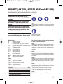
Hilti HIT (-HY 150, -HY 150 MAX and -RE 500)
Installation Instructions for fastenings in concrete
Contents Page
1. Borehole drilling 12
2. Borehole preparation 13
3. Borehole cleaning 14
4. Injection of mortar 15
5. Installation of the element 17
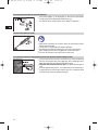
Safety Regulations:
Review the Material Safety Data Sheet (MSDS) before
use!
Wear well-fitting safety glasses, protective gloves and
suitable protective clothing when working with Hilti
HIT.
Read the Installation
Instructions for Use.
The following guidance will help you to find your way
in these installation instructions.
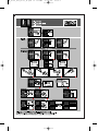
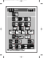
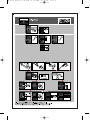
Step 1
Depending on the drilling method and the base mate-
rial condition (dry or water saturated / water filled /
underwater), choose one of the four installation meth-
ods. See Table I for the overview of the installation
methods.
Step 2
The sequence of the single steps in the overall proce-
dures is numbered and has to be followed accordingly.
The icons are explained in detail in the text part of these
instructions.
Step 3
Depending on the application condition and borehole
diameter, special accessories may be required. For the
proper choice of the accessories please refer to Table II.
Step 4
In order to reach the bottom of the borehole for a select-
ed installation procedure, the following tables will list the
appropriate elongations:
- Table III for the elongations used for brushing
- Table IV for the elongations used for air cleaning
- Table V for the elongations used for injecting
Step 5
Table VI lists the most appropriate HIT dispenser.
Abbreviations:
d
o
= Borehole diameter
d
s
= Element diameter
c= Concrete cover over the post installed
element (rebar applications)
c
drill
=
Distance of borehole axis to concrete surface
inst
= Embedment depth
m
= Mortar level mark
t
cure, full
= Full curing time
t
cure, ini
= Initial curing time
t
gel
= Gel / working time
Ø = Drill bit diameter
MSDS = Material Safety Data Sheet
HIT = Hilti Injection Technology
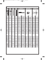
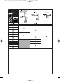
Tables:
Table I = Installation methods
Table II = Accessories selector
Table III = Brushing extension selector
Table IV = Blowing extension selector
Table V = Injection extension selector
Table VI = Dispenser selector
02_BA_HIT_Profi_P1_en.qxd 13.12.2006 13:37 Uhr Seite 11

12
en
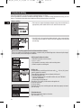
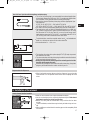
1. Borehole drilling
The drilling method has an influence on the setting procedure. See Table I.
In these installation instructions two different drilling methods, i.e. hammer drilling and diamond coring, are con-
sidered. For detailed information about additional drilling methods please contact Hilti.
• Drill hole to the required embedment depth using a hammer-drill with an
appropriately sized carbide drill bit set in rotation hammer mode.
•
Core drill hole to the required embedment depth using an appropriately
sized diamond core drill bit. Remove all core fragments from the hole
after drilling.
Special Case: Splicing applications for reinforcement bars (rebars)
To be in accordance with the design assumptions, concrete cover, parallel drilling to the surface and splice length
must be carefully ensured during the installation.
Splicing applications for rebars
•
Measure and verify concrete cover c.
•
c
drill
= c + d
s
/2
•
Drill parallel to concrete surface and to existing rebar.
•
Where required use drilling aid.
Drilling aid
Hammer drilling: use drilling aid for holes with
inst
> 20 cm (8") (check
specific approval for details).
Three different options may be considered a drilling aid:
A) Hilti drilling aid HIT-BH
•
Secure the drilling aid etc. with HKD-S M10×40 or HST M10/10
(HDI 3/8" or KB3 3/8").
•
Drill parallel to the guide rod.
Precaution: Put a clearly visible mark on the guide rod.
B) Slat or spirit level
C) Visual control
Diamond core rigs serve as drilling aids and need to be properly anchored
prior to coring.
Embedment mark
Mark the embedment depth on the rebar
(e.g. with tape) →
inst
.
Hammer drilling
Diamond coring
02_BA_HIT_Profi_P1_en.qxd 13.12.2006 13:37 Uhr Seite 12

13
en
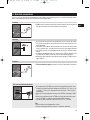
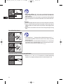
2. Borehole preparation
For use in case of: diamond cored boreholes, holes filled with standing water and / or under water applications,
observe the following steps prior to the borehole cleaning procedure.
•
Flush hole by inserting a water hose (water-line pressure) to the back of
the hole until water runs clear. Perform this step twice.
•
Brush the hole 2 times with the specified brush size (brush Ø ≥ bore-
hole Ø) by inserting the round steel brush to the back of the hole in a
twisting motion.
•
The brush shall produce natural resistance as it enters the anchor hole.
If this is not the case, use a new brush or a brush with a larger diameter.
•
See Table II for the corresponding round steel brush / drill bit combi-
nation.
•
If required, extend the reach of a steel brush, HIT-RB, by attaching it to
an extension HIT-RBV in order to reach the back of the borehole.
•
Attach the other extension end into the brush handle HIT-RBH, accord-
ing to Table III.
•
Flush the borehole again until water runs clear. Perform this step twice.
Special Case: Machine Brushing
0
0
•
Brush extensions HIT-RBS for machine brushing shall be used to acco-
modate cleaning of boreholes deeper than 250 mm (10”) (for d
s
= 8
mm (3/8")…12 mm (1/2") or deeper than 20 xd
s
(for d
s
> 12 mm (1/2")),
respectively.
•
Select the corresponding brush extension HIT-RBS according to Table
III.
•
Attach the round steel brush, HIT-RB, on to one end of the brush exten-
sion(s) HIT-RBS, in order to reach the back of the borehole.
•
Secure the other extension end into the TE-C/TE-Y (-T) holder.
Tips:
•
Start machine brushing operation slowly.
•
Start brushing operation once brush is inserted in borehole.
Flushing
Brushing
Flushing
02_BA_HIT_Profi_P1_en.qxd 13.12.2006 13:37 Uhr Seite 13

14
en
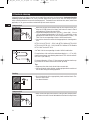
3. Borehole cleaning
Load performances of chemical anchors are strongly influenced by the cleaning method. Inadequate borehole
cleaning = poor load values. For safety relevant applications, please verify with the design engineer
which cleaning method was assumed in the design phase. The borehole must be free of dust, debris, water when
applicable, ice, oil, grease and other contaminants prior to mortar injection.
0
0
•
Blow from the back of the borehole with oil-free compressed air [min.
90 psi at 3.5 CFM (6 bar at 6 m
3
/hour)] until return air stream is free of
noticeable dust. Perform this step 2 times.
•
For boreholes deeper than 250 mm (10") (for d
s
= 8 mm (3/8") …12 mm
(1/2")) or deeper than 20xd
s
(for d
s
>12 mm (1/2")), respectively, use the
appropriate air nozzle Hilti HIT-DL (oil free compressed air ≥ 6 bar) – see
Table II for the corresponding air nozzle / drill bit combination.
•
Connect the selected air nozzle with the appropriate air cleaning exten-
sion:
HIT-DL 12–16 (HIT-DL 1/2" – 11/16") with HIT-DL 10/0.8 or HIT-DL V10/1
HIT-DL 18–32 (HIT-DL 3/4" – 1 3/8") with HIT-DL 16/0.8 or HIT-DL B and/or
HIT-VL 16/0.7 and/or HIT-VL 16.
See Table II for the corresponding air nozzle / drill bit combination.
For applications with an effective embedment depth
inst
> 0.7 m (28"),
please connect two or more blowing extensions HIT-DL with the connect-
or HIT-DL K (See Table IV).
For element diameter > 25 mm (1") the compressor must be rated to sup-
ply a minimum air flow of at least 140 m
3
/hour (82 CFM).
Tips:
•
Keep away from dust cloud, do not inhale concrete dust.
•
Hilti recommends a dust collector or other equipment to be used to col-
lect the dust during the blowing operation.
•
Brush the borehole with an appropriately sized round steel brush. Per-
form this step 2 times.
•
See above for details.
•
Blow out the hole again from the back of the hole with compressed air
until return air stream is free of noticeable dust. Perform this step 2 times.
Compressed air
Brushing
Compressed air
02_BA_HIT_Profi_P1_en.qxd 13.12.2006 13:37 Uhr Seite 14

15
en
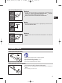
Special Case: Manual Cleaning
0
0
4x
Blowing out
•
The Hilti manual pump may be used for blowing out boreholes up to
diameters d
s
≤ 16 mm (5/8") and borehole depths up to
inst
≤ 250 mm
(10") (please contact Hilti for further references).
•
Blow out at least 4 times from the back of the borehole.
Brushing
•
Brush the borehole 4 times with an appropriately sized round steel
brush. See above for details.
Blowing out
•
Blow out at least 4 times from the back of the borehole. See above for
details.
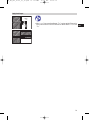
4. Injection of mortar
•
Observe the instructions for use of the dispenser.
•
Check foil pack holder for proper function.
•
Put foil pack into foil pack holder.
•
Do not use damaged foil packs/ holders.
•
Use the static mixer that is delivered with the mortar.
•
Attach the static mixer tightly on to the manifold before starting to dis-
pense.
•
Do not modify the static mixer.
Insert foil pack in foil pack holder
Tightly attach mixer to foil pack manifold
02_BA_HIT_Profi_P1_en.qxd 13.12.2006 13:37 Uhr Seite 15

16
en
•
Push release trigger (1), retract plunger (2) and insert foil pack holder
with foil pack into the appropriate Hilti dispenser (3).
•
See Table VI for the selection of the most suitable HIT dispenser.
0
0
•
Observe the Instructions for Use of the mortar for the amount of mortar
that has to be discarded.
•
The foil pack is self opening when dispensing begins.
•
Do not pierce the foil pack manually (this can cause system failure).
•
After changing a mixer, the first trigger pulls must be discarded.
•
For each new foil pack a new static mixer must be used.
•
Inject the mortar from the back of the borehole by slowly withdrawing
the mixer incrementely after each trigger pull, after controlling that the
depth of the borehole corresponds to the design value.
•
Important! Use extensions for deep holes, as explained under special
case.
•
Fill holes approximately 2/3 full, or as required to ensure that the annu-
lar gap between the anchor/rebar and the concrete is completely filled
with mortar over the entire embedment length.
Insert foil pack holder with foil pack into dispenser
Discard initial amount of mortar
Inject mortar into borehole starting from the back of the borehole without forming air voids
02_BA_HIT_Profi_P1_en.qxd 13.12.2006 13:37 Uhr Seite 16

17
en
Special Case: Injection with elongations and piston plug
•
The use of the piston plug is recommended for overhead applications
or boreholes deeper than 250 mm (10"). For underwater applications
the installation is only possible with the aid of piston plugs.
•
Connect the selected injection piston plug with the appropriate injec-
tion extension:
HIT-SZ 12–16 (HIT-SZ 1/2" – 5/8") with HIT-VL 9/1.0
HIT-SZ 18–32 (HIT-SZ 11/16" – 1 3/4") with HIT-VL 16 or HIT-VL 16/0.7
•
See Table II for the corresponding piston plug / drill bit combination.
•
For applications with an effective embedment depth
inst
> 800 mm
(31"), please connect two or more injection extensions HIT-VL using
the connector HIT-VL K (See Table V). In case of use of two or more
rigid injection extensions HIT-VL 16/0.7, use a flexible tube HIT-VL 16
(0.5 m /20") prior to the connection to the static mixer.
•
To aid installation, mark the required mortar level
m
and embedment
depth
inst
with tape or marker on the mixer extension.
•
Quick estimation:
m
= 1/3 •
inst
.
•
The injection of mortar with a piston plug HIT-SZ (IP) helps to prevent
the creation of air voids.
•
The mixer extension with the piston plug should be inserted to the back
of the borehole without resistance.
•
During the injection the piston plug will be naturally pushed out the
borehole by the mortar pressure.
•
Attention! By pulling the mixer extension with piston plug, the piston
plug may be rendered inactive and air voids may occur.
5. Installation of the element
•
Mark the anchor/rebar at the required embedment depth.
•
Set the anchor/rebar to the required embedment depth. Embedment
depth must equal to the design specification.
•
Before use, verify that the anchor/rebar is dry and free of oil or other
residue.
•
To ease installation, anchor/rebar may be slowly twisted as they are inser-
ted.
•
After installing an anchor/rebar the annular gap must be completely filled
with mortar.
Insert element into the borehole
•
After injecting the mortar depressurize the dispenser by pressing the
release button. This will prevent further mortar from escaping out of the
mixer.
Depressurize the dispenser
02_BA_HIT_Profi_P1_en.qxd 13.12.2006 13:37 Uhr Seite 17

18
en
0
0
t
cure
•
Once the gel time “t
gel
” has elapsed, do not disturb the element until “t
cure
”
has passed. Please refer to the Instructions for Use of the mortar for
details about “t
cure
”.
•
For rebar applications, do not disturb the element until “t
cure,ini
” has passed,
if the mortar in use is characterised by “t
cure,ini
”, please refer to the Instruc-
tions for Use of the mortar for details about “t
cure,ini
”.
•
Between “t
cure,ini
” and “t
cure,full
” the mortar has a limited load bearing
capacity. Do not apply the design load on the rebar during this time.
Do not disturb the element
Preparation work may continue for rebar applications
•
Observe the gel time “t
gel
”, which varies according to the temperature
of base material. Please refer to the Instructions for Use of the mortar for
details about t
gel
.
•
Minor adjustments to the anchor/rebar may be performed during the gel
time. For the gel time see relevant information in the manual of the mor-
tars.
Attention!
•
For overhead applications take special care when inserting the anchor/rebar.
•
Excess mortar will be forced out of the borehole. Collect and remove it
safely to protect the installer and the anchor/rebar. Avoid dripping of the
mortar.
•
Position the anchor/rebar and secure it from falling during the curing
time.
0
t
gel
l
inst
0
02_BA_HIT_Profi_P1_en.qxd 13.12.2006 13:37 Uhr Seite 18

19
en
•
After “t
cure,full
” has passed load/torque “T
inst
” may be applied. Please refer
to the Instruction for Use of the mortar for details about “t
cure,full
” and
“T
inst
”
Apply load/torque
02_BA_HIT_Profi_P1_en.qxd 13.12.2006 13:37 Uhr Seite 19

02_BA_HIT_Profi_P1_en.qxd 13.12.2006 13:37 Uhr Seite 20

HAS HIS Rebar HIT-RB HIT-SZ (IP) HIT-DL
Ø [mm] Ø [mm] Ø [mm] Ø [mm] Item no. Item no. Item no.
10 810380917 – – – –
12 10 8 8/12 336548 8/12 351989 8/12 371715
14 12 8 10 10/14 336549 10/14 351990 10/14 371716
16 12 12/16 336550 12/16 351991 12/16 371717
18 16 10 14 14/18 336551 14/18 351992 14/18 371718
20 16 16/20 336552 16/20 351993 16/20 371719
22 12 18 18/22 370774 18/22 269618 16/20 371719
24 20 24 380918 24 269619 16/20 371719
25 20 20/25 336553 20/25 351994 20/25 371720
28 24 16 22 28 380919 28 269620 20/25 371720
30 27 30 380920 30 269621 20/25 371720
32 20 25 25/32 336554 25/32 351995 25/32 371721
35 30 28 35 380921 35 269622 25/32 371721
37 33 30 37 382259 37 271499 25/32 371721
40 36 32 40 382260 40 269623 25/32 371721
42 42 382261 42 269624 25/32 371721
45 39 36 45 382262 45 269625 25/32 371721
47 47 382264 47 269626 25/32 371721
52 52 382265 52 271476 25/32 371721
55 40 55 382266 55 271477 25/32 371721
Ø [inch] Ø [inch] Ø [inch] Ø [inch] Item no. Item no. Item no.
7/16 3/8 7/16" 273203 – – –
1/2 #3 1/2" 273204 1/2" 274019 1/2" 38237
9/16 1/2 9/16" 273205 9/16" 274020 9/16" 38238
5/8 #4 5/8" 273207 5/8" 274021 9/16" 38238
11/16 3/8 11/16" 273209 11/16" 274022 11/16" 38239
3/4 5/8 #5 3/4" 273210 3/4" 274023 3/4" 38240
7/8 3/4 1/2 #6 7/8" 273211 7/8" 274024 7/8" 38241
1 7/8 #7 1" 273212 1" 274025 1" 38242
1 1/8 1 5/8 #8 1 1/8" 273214 1 1/8" 274026 1" 38242
1 1/4 3/4 1 1/4" 273216 1 1/4" 274027 1" 38242
1 3/8 1 1/4 #9 1 3/8" 273217 1 3/8" 274028 1 3/8" 38243
1 1/2 #10 1 1/2" 273218 1 1/2" 274029 1 3/8" 38243
1 3/4 1 1/2 #11 1 3/4" 273219 1 3/4" 274030 1 3/8" 38243
II
00_Cover_HIT_Profi_P1.qxd 13.12.2006 13:33 Uhr Seite 5

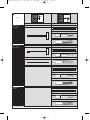
1)
Depending on drilling machine
1)
Ça depend du perforateur
1)
Depende del marillo perforador
III
Item Item no.
1 HIT-RBS 10/0.35 371722
TE-C
1)
263437
TE-Y
1)
263439
Item Item no.
1 HIT-RBH 229138
0–250 mm
(0"–10")
1–2 HIT-RBS 10/0.35 371722
TE-C
1)
263437
TE-Y
1)
263439
1 HIT-RBH 229138
HIT-RBV 238727
HIT-RBS 10/0.7 336645
TE-C
1)
263437
TE-Y
1)
263439
1–x Brush RBS 10/0.7 336645
TE-C
1)
263437
TE-Y
1)
263439
250–800 mm
(10"–31")
>800 mm
(> 31")
inst
0
0
00_Cover_HIT_Profi_P1.qxd 13.12.2006 13:33 Uhr Seite 6

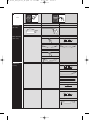
IV
Item Item no.
G 1/4" 381215
Item Item no.Item Item no.
Handpump 60579
0–250 mm
(0"–10")
G 1/4" 381215
HIT-DL 10/0.8 38251
HIT-DL A 336643
HIT-DL V10/1 336644
G 1/4" 381215
HIT-DL 16/0.8 38252
HIT-DL A 336643
HIT-DL B 371714
HIT-VL 16/0.7 336646
HIT-DL K 038250
HIT-DL A 336643
HIT-VL 16 038249
250–800 mm
(10"–31")
>800 mm
(> 31")
inst
00_Cover_HIT_Profi_P1.qxd 13.12.2006 13:33 Uhr Seite 7

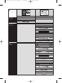
V
Item Item no.Item Item no.
HIT-M1 068156
HIT-M3 348071
HIT-RE-M 337111
0–250 mm
(0"–10")
HIT-M1 068156
HIT-M3 348071
HIT-RE-M 337111
HIT-VL 16 038249
HIT-M1 068156
HIT-M3 348071
HIT-RE-M 337111
HIT-VL 9/1.0 024632
250–800 mm
(10"–31")
HIT-M1 068156
HIT-M3 348071
HIT-RE-M 337111
HIT-VL 16 038249
1-x HIT-VL 16/0.7 336646
HIT-VL K
HIT-M1 068156
HIT-M3 348071
HIT-RE-M 337111
HIT-VL 16 038249
HIT-VL K
>800 mm
(> 31")
inst
00_Cover_HIT_Profi_P1.qxd 13.12.2006 13:33 Uhr Seite 8

VI
00_Cover_HIT_Profi_P1.qxd 13.12.2006 13:33 Uhr Seite 9
Page is loading ...
-
 1
1
-
 2
2
-
 3
3
-
 4
4
-
 5
5
-
 6
6
-
 7
7
-
 8
8
-
 9
9
-
 10
10
-
 11
11
-
 12
12
-
 13
13
-
 14
14
-
 15
15
-
 16
16
-
 17
17
-
 18
18
-
 19
19
-
 20
20
-
 21
21


Ask a question and I''ll find the answer in the document
Finding information in a document is now easier with AI
Related papers
-
Hilti 3489736 Installation guide
-
Hilti 260346 Installation guide
-
-
-
-
-
-
-
-
Other documents
-
Miele RBS 36 User guide
-
 Newport MD2500 Epoxy Dispenser User manual
-
 Screening Eagle PROFOSCOPE Operating instructions
-
Plawa Scrivo.1 User manual
-
 Screening Eagle Profometer PM8000 Operating instructions
-
Westinghouse Y1SA Installation guide
-
-
Metabo KHE 75 Operating instructions
-
Proceq Profometer 5+ Operating Instructions Manual
-
Simpson Strong-Tie SET-XP22 Installation guide


