Sony sony mz-dh10p User manual
- Category
- Car audio amplifiers
- Type
- User manual
This manual is also suitable for

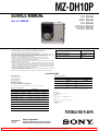
SERVICE MANUAL
PORTABLE MD PLAYER
MZ-DH10P
Ver. 1.2 2005.05
SPECIFICATIONS
9-879-552-03
2005E05-1
© 2005.05
Sony Corporation
Personal Communications Business Division
Published by Sony Engineering Corporation
US and foreign patents licensed from Dolby Laboratories.
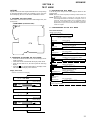
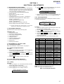
Model Name Using Similar Mechanism NEW
MD Mechanism Type MT-MZDH10P-181
Optical Pick-up Name ABX-UJ
US Model
AEP Model
UK Model
Chinese Model
Tourist Model
• SonicStage is trademark or registered trademark of Sony Corporation.
•MD Simple Burner, OpenMG, “MagicGate”, “MagicGate Memory Stick”, “Memory Stick”, Hi-MD, Net
MD, ATRAC, ATRAC3, ATRAC3plus and their logos are trademarks of Sony Corporation.
• Microsoft, Windows, Windows NT and Windows Media are trademarks or registered trademarks of Microsoft
Corporation in the United States and /or other countries.
• IBM and PC/AT are registered trademarks of International Business Machines Corporation.
•Macintosh is a trademark of Apple Computer, Inc. in the United States and/ or other countries.
•Pentium is a trademark or registered trademark of Intel Corporation.
• All other trademarks and registered trademarks are trademarks or registered trademarks of their respective
holders.
•™ and
®
marks are omitted in this manual.
• CD and music-related data from Gracenote, Inc., copyright © 2000-2004 Gracenote. Gracenote CDDB
®
Client Software, copyright 2000-2004 Gracenote. This product and service may practice one or more of the
following U.S. Patents: #5,987,525; #6,061,680; #6,154,773, #6,161,132, #6,230,192, #6,230,207, #6,240,459,
#6,330,593, and other patents issued or pending. Services supplied and/or device manufactured under license
for following Open Globe, Inc. United States Patent 6,304,523.
Gracenote is a registered trademarks of Gracenote. The Gracenote logo and logotype, and the “Powered by
Gracenote” logo are trademarks of Gracenote.
Program © 2001, 2002, 2003, 2004, 2005 Sony Corporation Documentation © 2005 Sony Corporation
!UDIOPLAYINGSYSTEM
-INI$ISCDIGITALAUDIOSYSTEM
,ASERDIODEPROPERTIES
-ATERIAL'A!L!S-17
7AVELENGTH
LNM
2ECORDINGANDPLAYBACKTIME
2EVOLUTIONS
!PPROXRPMTORPM#,6
%RRORCORRECTION
(I-$
,$#,ONG$ISTANCE#ODE")3"URST)NDICATOR
3UBCODE
-$
!#)2#!DVANCED#ROSS)NTERLEAVE2EED3OLOMON
#ODE
3AMPLINGFREQUENCY
K(Z
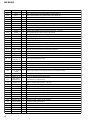
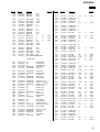
,ISTOFTHERECORDINGTIMEFOREACHDISC!PPROX
4HERECORDINGTIMEISVARIEDDEPENDINGONDISCTYPEDISCMODECODECANDBITRATE
7HENUSINGADISCIN(I-$MODE
2ECORDINGTIME*
#ODEC"ITRATE '"(I-$DISC MINUTE
STANDARDDISC
MINUTE
STANDARDDISC
MINUTE
STANDARDDISC
,INEAR0#--BPS HOURAND
MINUTES
MINUTES MINUTES MINUTES
!42!#PLUSKBPS HOURSAND
MINUTES
HOURSAND
MINUTES
HOURSAND
MINUTES
HOURAND
MINUTES
!42!#PLUSKBPS HOURS HOURSAND
MINUTES
HOURSAND
MINUTES
HOURSAND
MINUTES
!42!#PLUSKBPS HOURS HOURSAND
MINUTES
HOURSAND
MINUTES
HOURS
!42!#KBPS HOURSAND
MINUTES
HOURSAND
MINUTES
HOURSAND
MINUTES
HOURSAND
MINUTES
!42!#KBPS HOURSAND
MINUTES
HOURSAND
MINUTES
HOURSAND
MINUTES
HOURSAND
MINUTES
!42!#KBPS HOURSAND
MINUTES
HOURSAND
MINUTES
HOURS HOURSAND
MINUTES
-0KBPS HOURS HOURS HOURSAND
MINUTES
HOURSAND
MINUTES
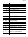
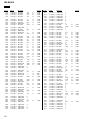
7HENUSINGADISCIN-$MODE
2ECORDINGTIME*
#ODEC"ITRATE MINUTE
STANDARDDISC
MINUTESTANDARD
DISC
MINUTE
STANDARDDISC
!42!#STEREOKBPS HOURAND
MINUTES
HOURAND
MINUTES
HOUR
!42!#KBPS HOURSAND
MINUTES
HOURSAND
MINUTES
HOURS
!42!#KBPS HOURSAND
MINUTES
HOURAND
MINUTES
HOURS
7HENTRANSFERRINGMINUTETRACKS
-0lLEFORMATSAREASFOLLOWS-0%'!UDIO,AYERSAMPLINGFREQUENCYK(ZlXEDBITRATE
For other Service and User Manuals, go to www.ManualDepot.com

MZ-DH10P
2
0LAYABLEAUDIOFORMAT
,INEAR0#-K(ZBIT
!42!#PLUS!DAPTIVE42ANSFORM!COUSTIC
#ODINGPLUS
!42!#
!42!#
-0-0%'!UDIO,AYERSAMPLINGFREQUENCY
K(ZBITRATEKBPSlXEDVARIABLEBIT
RATE
-ODULATIONSYSTEM
(I-$
2,,2UN,ENGTH,IMITED02-,0ARTIAL
2ESPONSE-AXIMUM,IKELIHOOD
-$
%&-%IGHTTO&OURTEEN-ODULATION
&REQUENCYRESPONSE7HENOUTPUTTINGTHROUGH
EARPHONE
TO(ZD"
/NPUTCONNECTOR
¦STEREOMINIJACKDEDICATEDREMOTEJACK
-AXIMUMOUTPUT$#
(EADPHONES
M7M77%UROPEANMODEL
M7M77/THERMODELS
)MAGEDEVICE
MMTYPECOLOR#-/3
0RIMARYCOLORlLTER
4OTALPIXELSNUMBEROFCAMERA
!PPROXPIXELS
%FFECTIVEPIXELSNUMBEROFCAMERA
!PPROXPIXELS
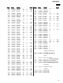
,ENS3INGLEFOCALLENS
FMMINCHESMMCAMERA
CONVERSIONMMINCHES&
%XPOSURECONTROL
!UTOMATIC
$ATAFORMATS
3TILLIMAGES$#&COMPLIANT
%XIF6ER*0%'COMPLIANT
&LASH
2ECOMMENDEDDISTANCEMTOMTO
FT
,#$SCREEN
MMINOPPOSITEANGLETYPE
4OTALNUMBEROFDOTS§DOTS
0OWERREQUIREMENTS
3ONY!#0OWER!DAPTORCONNECTEDATTHE$#
).6JACK
$IMENSIONS
!PPROX§§MMWHD
§§INEXCLUDINGPROJECTINGPARTS
ANDCONTROLS
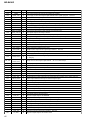
"ATTERYLIFE
4HISVALUEVARIESDEPENDINGONHOWTHEPLAYERISUSED
7HENLISTENINGTOMUSICHOUR!PPROX
(I-$MODE ,INEAR0#- (I30 (I,0 -0
'"(I-$DISC
MINUTE
STANDARDDISC
-$MODE 30 ,0 ,0
MINUTE
STANDARDDISC
-EASUREDINACCORDANCEWITHTHE*%)4!*APAN%LECTRONICSAND)NFORMATION4ECHNOLOGY)NDUSTRIES!SSOCIATION
STANDARD
7HENUSINGAFULLYCHARGEDLITHIUMIONRECHARGEABLEBATTERY
7HENTRANSFERRINGATKBPS
7HENVIEWINGSTILLIMAGESWHILELISTENINGTOMUSICINTHESLIDESHOWHOUR!PPROX
(I-$MODE ,INEAR0#- (I30 (I,0 -0
'"(I-$DISC
MINUTE
STANDARDDISC
-EASUREDINACCORDANCEWITHTHE*%)4!*APAN%LECTRONICSAND)NFORMATION4ECHNOLOGY)NDUSTRIES!SSOCIATION
STANDARD
7HENSHOOTINGSTILLIMAGES!PPROX
)MAGESIZE .UMBEROFSTILLIMAGES
'"(I-$DISC
MINUTESTANDARDDISC
-EASUREDINACCORDANCEWITHTHE#)0!#AMERA)MAGING0RODUCTS!SSOCIATIONSTANDARD
3HOOTINGINTHEFOLLOWINGSITUATIONS
n3HOOTINGONETIMEEVERYSECONDS
n4HEmASHSTROBESONCEEVERYTWOTIMES
n4HEPOWERTURNSONANDOFFONCEEVERYTENTIMES
n4HEIMAGESIZEIS-&INE
7HENVIEWINGSTILLIMAGESHOUR!PPROX
)MAGESIZE "ATTERYLIFE
'"(I-$DISC
MINUTESTANDARDDISC
-EASUREDINACCORDANCEWITHTHE#)0!#AMERA)MAGING0RODUCTS!SSOCIATIONSTANDARD
6IEWINGSINGLESTILLIMAGESINORDERATABOUTSECONDINTERVALS
-ASS
!PPROXGOZTHEPLAYERONLY
!PPROXGOZINCLUDINGTHERECHARGEABLE
BATTERY
$ESIGNANDSPECIlCATIONSARESUBJECTTOCHANGE
WITHOUTNOTICE
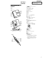
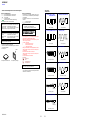
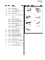
Supplied Accessories
AC power adaptor
Remote control
1)
USB cradle
Earphones
Dedicated USB cable
2)
LIP-4WM Lithium-ion rechargeable battery
Rechargeable battery case
Carrying pouch
Ferrite core (for the remote cord, AEP and UK models only)
CD-ROM
3)
(SonicStage/MD Simple Burner)
Operating Instructions
1) For US model, remote control with a ferrite core is supplied.
2) For Chinese and Tourist models, the ferrite core is not attached to the dedicated USB cable.
3) Do not play a CD-ROM on an audio CD player.
Ver. 1.2
6!#(Z/THERMODELS
4HEPLAYER
,ITHIUMIONRECHARGEABLEBATTERY
,)07-6M!H,IION
53"CRADLE
!#POWERADAPTOR$#6
/PERATINGTEMPERATURE
#&TO#&
"ATTERYOPERATIONTIME
120V AC, 60Hz (US model)
220V AC, 50Hz (Chinese model)

MZ-DH10P
3
TABLE OF CONTENTS
1. SERVICING NOTES ............................................... 4
2. GENERAL ................................................................... 5
3. DISASSEMBLY
3-1. Disassembly Flow ........................................................... 6
3-2. Panel (Bottom) Block ...................................................... 7
3-3. Camera Module ............................................................... 7
3-4. MAIN Board.................................................................... 8
3-5. Panel (Upper) Block ........................................................ 8
3-6. Ornamental Belt .............................................................. 9
3-7. Mechanism Deck (MT-MZDH10P-181),
Battery Case .................................................................... 9
3-8. Gear (SA), Gear (SB) ...................................................... 10
3-9. OP Service Assy .............................................................. 10
3-10. DC Motor SSM18D/C-NP (Spindle) (M701),
DC Motor SSM21A/C-NP (Sled) (M702),
DC Motor Unit (Over Write Head Up/Down) (M703) ... 11
3-11. Holder Assy ..................................................................... 11
3-12. Position Of Ferrite Core .................................................. 12
4. TEST MODE.............................................................. 13
5. ELECTRICAL ADJUSTMENTS .......................... 17
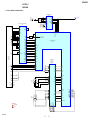
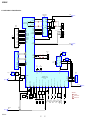
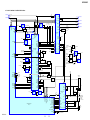
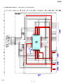
6. DIAGRAMS
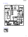
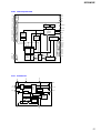
6-1. Block Diagram – MD SERVO Section – ........................ 21
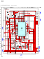
6-2. Block Diagram – AUDIO/CAMERA Section – .............. 22
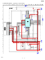
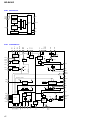
6-3. Block Diagram – POWER SUPPLY Section – ............... 23
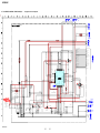
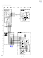
6-4. Schematic Diagram – MAIN Board (1/9) – .................... 25
6-5. Schematic Diagram – MAIN Board (2/9) – .................... 26
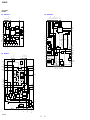
6-6. Schematic Diagram – MAIN Board (3/9) – .................... 27
6-7. Schematic Diagram – MAIN Board (4/9) – .................... 28
6-8. Schematic Diagram – MAIN Board (5/9) – .................... 29
6-9. Schematic Diagram – MAIN Board (6/9) – .................... 30
6-10. Schematic Diagram – MAIN Board (7/9) – .................... 31
6-11. Schematic Diagram – MAIN Board (8/9) – .................... 32
6-12. Schematic Diagram – MAIN Board (9/9) – .................... 33
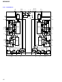
6-13. Printed Wiring Board
– MAIN Board (Component Side) – ............................... 34
6-14. Printed Wiring Board
– MAIN Board (Conductor Side) – ................................. 35
6-15. Printed Wiring Boards – PANEL Section –..................... 36
6-16. Schematic Diagram – PANEL Section – ......................... 37
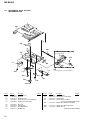
7. EXPLODED VIEWS
7-1. Overall Section ................................................................ 51
7-2. Panel (Upper) Section ..................................................... 52
7-3. Chassis Section ................................................................ 53
7-4. Mechanism Deck Section (MT-MZDH10P-181) ............ 54
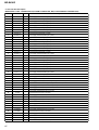
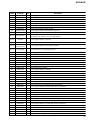
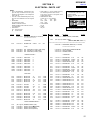
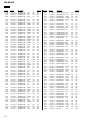
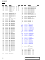
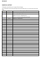
8. ELECTRICAL PARTS LIST................................ 55
Notes on chip component replacement
• Never reuse a disconnected chip component.
• Notice that the minus side of a tantalum capacitor may be
damaged by heat.
Flexible Circuit Board Repairing
• Keep the temperature of the soldering iron around 270 ˚C
during repairing.
• Do not touch the soldering iron on the same conductor of the
circuit board (within 3 times).
• Be careful not to apply force on the conductor when soldering
or unsoldering.
CAUTION
Use of controls or adjustments or performance of procedures
other than those specified herein may result in hazardous radiation
exposure.
SAFETY-RELATED COMPONENT WARNING!!
COMPONENTS IDENTIFIED BY MARK 0 OR DOTTED LINE
WITH MARK 0 ON THE SCHEMATIC DIAGRAMS AND IN
THE PARTS LIST ARE CRITICAL TO SAFE OPERATION.
REPLACE THESE COMPONENTS WITH SONY PARTS WHOSE
PART NUMBERS APPEAR AS SHOWN IN THIS MANUAL OR
IN SUPPLEMENTS PUBLISHED BY SONY.
/NPOWERSOURCES
s&ORUSEINYOURHOUSE&ORTHESUPPLIED53"
CRADLEUSETHE!#POWERADAPTORSUPPLIED
WITHTHISPLAYER$ONOTUSEANYOTHER!#
POWERADAPTORSINCEITMAYCAUSETHEPLAYER
TOMALFUNCTION
Ver. 1.2

4
MZ-DH10P
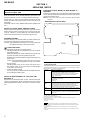
SECTION 1
SERVICING NOTES
The laser diode in the optical pick-up block may suffer electrostatic
break-down because of the potential difference generated by the
charged electrostatic load, etc. on clothing and the human body.
During repair, pay attention to electrostatic break-down and also
use the procedure in the printed matter which is included in the
repair parts.
The flexible board is easily damaged and should be handled with
care.
NOTES ON LASER DIODE EMISSION CHECK
The laser beam on this model is concentrated so as to be focused on
the disc reflective surface by the objective lens in the optical pick-
up block. Therefore, when checking the laser diode emission,
observe from more than 30 cm away from the objective lens.
NOTES ON HANDLING THE OPTICAL PICK-UP
BLOCK OR BASE UNIT
OPERATION CHECK WHEN THE MAIN BOARD IS
REMOVED
In making an operation check with the MAIN board removed from
the set, short the SL894 of the MAIN board with the solder before
starting the operation check.
Note: Be sure to remove the solder used for shortcircuit after the repaire
completed.
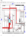
– MAIN BOARD (Conductor Side) –
SL894
UNLEADED SOLDER
Boards requiring use of unleaded solder are printed with the lead-
free mark (LF) indicating the solder contains no lead.
(Caution: Some printed circuit boards may not come printed with
the lead free mark due to their particular size)
: LEAD FREE MARK
Unleaded solder has the following characteristics.
• Unleaded solder melts at a temperature about 40 °C higher
than ordinary solder.
Ordinary soldering irons can be used but the iron tip has to be
applied to the solder joint for a slightly longer time.
Soldering irons using a temperature regulator should be set to
about 350 °C.
Caution: The printed pattern (copper foil) may peel away if
the heated tip is applied for too long, so be careful!
• Strong viscosity
Unleaded solder is more viscou-s (sticky, less prone to flow)
than ordinary solder so use caution not to let solder bridges
occur such as on IC pins, etc.
• Usable with ordinary solder
It is best to use only unleaded solder but unleaded solder may
also be added to ordinary solder.
Providing the required system environment
The following system environment is required in order to use the SonicStage Ver. 3.0/MD
Simple Burner Ver. 2.0 software for the MD Walkman.
This software is not supported by the following environments:
• OSs other than the indicated above
• Personally constructed PCs or operating systems
• An environment that is an upgrade of the original manufacturer-installed operating system
• Multi-boot environment
• Multi-monitor environment
• Macintosh
• We do not ensure trouble-free operation on all computers that satisfy the system requirements.
• The NTFS format of Windows XP/Windows 2000 Professional can be used only with the standard
(factory) settings.
• For Windows 2000 Professional users, install Service Pack 3 or later version before using the
software.
• We do not ensure trouble-free operation of the system suspend, sleep, or hibernation function on all
computers.
System requirements
Computer IBM PC/AT or Compatible
•CPU: Pentium III 450 MHz or higher
•Hard disk drive space: 200 MB or more (1.5 GB or more is
recommended) (The amount space will vary according to Windows
version and the number of music files stored on the hard disk.)
•RAM: 128 MB or more
Others
•CD drive (capable of digital playback by WDM) (A CD-R/RW drive
is necessary for CD writing)
•Sound Board
•USB port
Operating
System
Factory installed:
Windows XP Media Center Edition 2005/Windows XP Media Center
Edition 2004/Windows XP Media Center Edition/Windows XP
Professional/Windows XP Home Edition/Windows 2000 Professional/
Windows Millennium Edition/Windows 98 Second Edition
Display High Color (16bit) or higher, 800 u 600 dots or better (1024 u 768 dots
or better is recommended)
Others • Internet access: for Web registration, EMD services and CDDB
•Windows Media Player (version 7.0 or higher) installed for playing
WMA files
Notes
NOTES ON REPLACEMENT OF CSP (CHIP SIZE
PACKAGE) IC
Replacement of MM1690LCBE (IC401), SN761059AZQLR
(IC501), SC901585VAR2 (IC601), CXD2683-225GG (IC801) and
S29PL032J55BFI120A (IC802) used in this set requires a special
tool.

5
MZ-DH10P
SECTION 2
GENERAL
This section is extracted from
instruction manual.
Ȣ
SHOOTINGVIEWINGBUTTON
ȣ
3HUTTERBUTTON
Ȥ
0LAYER6/,
nBUTTONS
2EMOTE6/,nCONTROL
ȥ
$/7.,/!$
BUTTON
Ȧ
(/,$SWITCH
ȧ
"ATTERYCOMPARTMENT
Ȩ
&LASH
ȩ
-IRROR
Ȫ
,ENS
ȫ
,ENSCOVER!5$)/0(/4/
Ȭ
¦
EARPHONESJACK
ȭ
#('LAMP
Ȯ
0LAYER
ý
STOP#!.#%,BUTTON
2EMOTE
ý
STOPBUTTON
ȯ
*OGDIAL
Ȱ
s$)30,!9
3,)$%3(/7BUTTON
ȱ
/0%.SWITCH
Ȳ
$ISPLAY
2EMOTE
Ȧ
ȸ
ȹ
Ȥ
ȳ
Ȯ
Ⱥ
'UIDETO0ARTSAND
#ONTROLS
0LAYER
Ȣ
ȣ
Ȥ
ȥ
Ȧ
ȧ
Ȫ
ȫ
Ȩ
ȩ
Ȭ
ȭ
Ȯ
ȯ
Ȱ
Ȳ
ȴ
ȵ
ȶ
ȷ
ȳ
ȱ
ȳ
0LAYERWAYCONTROLKEY
¼ú%.4
Ê n
2EMOTE
úBUTTON
ȴ
3%!2#(BUTTON
ȵ
/02LAMP
ȶ
-%.5BUTTON
ȷ
#ONNECTORFORTHE53"CRADLE
ȸ
#LIP
ȹ
GROUPnBUTTON
Ⱥ
¼ÊBUTTON
4HEREISTACTILEDOT
4OREADMUSICTRACKSONTOADISCDIRECTLYFROM
ANAUDIO#$INTHE#$DRIVEOFYOURCOMPUTER
USING-$3IMPLE"URNERUSETHISBUTTON.
7HENTHELENSCOVERISCLOSEDTHEPLAYERISIN
THEMUSICMODE7HENTHELENSCOVERISOPEN
THEPLAYERISINTHESHOOTINGMODEORINTHE
VIEWINGMODE

MZ-DH10P
6
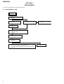
• This set can be disassembled in the order shown below.
3-1. DISASSEMBLY FLOW
SECTION 3
DISASSEMBLY
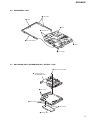
3-2. PANEL (BOTTOM) BLOCK
(Page 7)
3-3. CAMERA MODULE
(Page 7)
3-7. MECHANISM DECK (MT-MZDH10P-181),
BATTERY CASE
(Page 9)
3-8. GEAR (SA), GEAR (SB)
(Page 10)
3-4. MAIN BOARD
(Page 8)
3-9. OP SERVICE ASSY
(Page 10)
3-10. DC MOTOR SSM18D/C-NP (SPINDLE) (M701),
DC MOTOR SSM21A/C-NP (SLED) (M702),
DC MOTOR UNIT (OVER WRITE HEAD UP/DOWN) (M703)
(Page 11)
3-11. HOLDER ASSY
(Page 11)
3-5. PANEL (UPPER) BLOCK
(Page 8)
3-6. ORNAMENTAL BELT
(Page 9)
SET

MZ-DH10P
7
qs
four claws
7
Slide the knob (open) in the direction of arrow
A
,
and open the panel (upper) block in the direction of arrow
B
.
0
sheet
9
connector
qa
flexible (S-V) board
(CN202)
qd
panel side block
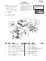
5
screw (M1.4)
4
battery case lid
6
two screws
(M1.4)
qf
panel (bottom) block
2
two screws
(M1.4)
1
screw
(M1.4)
qs
two claws
A
B
8
knob (open)
3
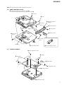
Open the battery case lid.
5
three toothed lock screws
3
two sheets
1
sheet
2
flexible board
6
toothed lock scre
w
7
camera module
4
flexible (M-C) board
3-3. CAMERA MODULE
Note: Follow the disassembly procedure in the numerical order given.
3-2. PANEL (BOTTOM) BLOCK

MZ-DH10P
8
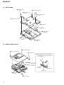
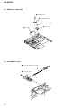
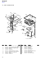
3-4. MAIN BOARD
3-5. PANEL (UPPER) BLOCK
5
two toothed lock
screws
1
Remove two solders.
7
two toothed lock
screws
8
three toothed lock
screws
9
MAIN board
3
sheet
2
flexible boar
d
(CN491)
2
flexible board
(CN701)
2
flexible board
(CN501)
6
holder (connector)
2
two screws (M1.4)
6
panel (upper) block
3
screw (M1.4)
4
screw (M1.4)
1
connector
(CN201)
5
Two flexible boards are drawn from the
space between the ornamental belt and
the chassis block.
chassis block
connector
(CN201)
ornamental belt

MZ-DH10P
9
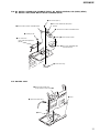
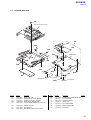
3-6. ORNAMENTAL BELT
3-7. MECHANISM DECK (MT-MZDH10P-181), BATTERY CASE
7
ornamental belt
3
claw
5
two claws
2
two bosses
4
boss
6
bos
s
1
two bosses
1
two step screws (MD)
2
mechanism deck
(MT-MZDH10P-181)
3
two claws
3
three claws
5
battery case
4
two bosses

MZ-DH10P
10
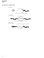
1
self tap screw
2
thrust retainer spring
3
washer (0.8-2.5)
4
gear (SA)
5
gear (SB)
1
Lead screw block assy is turned
and it removes from OP service assy.
2
OP service assy
3-8. GEAR (SA), GEAR (SB)
3-9. OP SERVICE ASSY

MZ-DH10P
11
3
two screws (M1.4)
4
DC motor SSM21A/C-NP (sled)
(M702)
1
Remove four solders of flexible board.
2
Remove two solders of flexible board.
6
three self tap screws
7
DC motor SSM18D/C-NP
(spindle) (M701)
5
motor base assy
9
DC motor unit
(over write head up/down)
(M703)
8
self tap screw
4
Remove the holder assy
to the direction of the arrow
A
.
3
Open the holder assy.
1
boss
2
boss
A
3-10. DC MOTOR SSM18D/C-NP (SPINDLE) (M701), DC MOTOR SSM21A/C-NP (SLED) (M702),
DC MOTOR UNIT (OVER WRITE HEAD UP/DOWN) (M703)
3-11. HOLDER ASSY

MZ-DH10P
12
3-12. POSITION OF FERRITE CORE
4cm
4cm 4cm
4cm
A cable is rolled twice.
A cable is rolled onece.
A cable is rolled onece.
clamp filter (ferrite core) (Part No. 1-400-878-11)
clamp filter (ferrite core) (Part No. 1-400-878-11)
clamp filter (ferrite core) (Part No. 1-400-877-11)
-AC ADAPTOR-
-REMOTE CONTROL-
(US, AEP, UK models)
-USB CABLE-
(US, AEP, UK models)
Ver. 1.1

13
MZ-DH10P
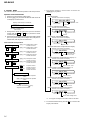
2. OPERATION IN SETTING THE TEST MODE
• When the test mode becomes active, first the Display Check
mode is selected.
• Other mode can be selected from the Display Check mode.
• When the test mode is set, the LCD repeats the following
display.
• When the x key is pressed and hold down, the display at that
time is held so that display can be checked.
Display check mode:
OUTLINE
Operation in the test mode is performed with the set. A key having
no particular description in the text, indicates a set key. Also, For
the LCD display, the LCD on the remote commander is shown.
1. ENTERING THE TEST MODE
Short SL801 on the MAIN board with a solder bridge. Then, turn
on the power.
SECTION 4
TEST MODE
Display Check Mode
Version display
→
All lit
→
All off
→
Version display...
[VOL +]
key
x
key
x
key
u
ENT
key
x
key
>
key
x
key
[DOWNLOAD]
key
[DISPLAY]
key
[VOL --]
key
x
key
Open the lid
Manual Mode
Sound Skip Check Result
Display Mode (Play)
Self-Diagnosis Result Display Mode
Sound Skip Check Result
Display Mode (REC)
Key Check Mode
Overall Adjustment Mode
Key Count Mode
[DISPLAY]
key
(press a
few seconds)
[DISPLAY]
key
(press a few seconds)
(Not used in servicing)
000 Manual
000 1 0000
000 P00r00
000 p00R00
000 MENU 000
110 10
000 AdjF**
012 V1.000
– MAIN BOARD (Conductor Side) –
SL801
All lit
Remote commander LCD display
All off
All lit
All off
Back-end FW
version display
Front-end FW
version display
888
012 V*.***
F
1SHUFPGM SOUND
V-SUR
8
888
012 ******
F
1SHUFPGM SOUND
V-SUR
8
3. RELEASING THE TEST MODE
Turn off the power and open the solder bridge on SL801 on the
MAIN board.
Note1: Remove the solders completely. Remaining could be shorted with
the chassis, etc.
Note2: When the power supply is switched on in the state where all
electrical adjustments have not finished, it is displayed on LCD as
“Error EE’’ and the usual operation can’t be performed. When a
power supply is accidentally turn off in the middle of electrical
adjustments, it is again set as test mode and electrical adjustments
is mode to complete.
4. CONFIGURATION OF THE TEST MODE
Flow of the test mode:

14
MZ-DH10P
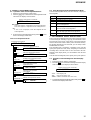
5. MANUAL MODE
This is mode to adjust or check the operation of the set by function.
Operation of The Manual Mode
1. Enter the test mode (Display Check mode).
2. Press the [VOL+] key to activate the Manual mode where the
LCD displays as shown below.
Display of the remote commander
3. During Manual mode, the optical pick-up moves outward or
inward while the > or . key is pressed for several
seconds respectively.
4. Each test item is assigned with a four-digit item number; 1000th
place is a top item, 100th place is a major item, 10th place is a
medium item, and unit place is a minor item.
Flow of manual mode operation:
Number of 1000th place
(000 to 009)
000 Manual
x
key
>
key
>
key
>
key
Top item switching
Major item switching
x
key
[VOL +]
key: 1000th place of item
number increase.
[VOL --]
key: 1000th place of item
number decrease.
[VOL +]
key: 100th place of item
number increase.
[VOL --]
key: 100th place of item
number decrease.
Medium item switching
x
key
[VOL +]
key: 10th place of item
number increase.
[VOL --]
key: 10th place of item
number decrease.
>
key: 1st place of item
number increase.
.
key: 1st place of item
number decrease.
Minor item switching
[VOL +]
key: Increases the adjusted
value.
[VOL --]
key: Decreases the adjusted
value.
Adjusted value variation
Adjusted value write
[
ENT
]
key:
u
Set
[ +],
[
--
]
key:
Remote commander
Adjusted value is written.
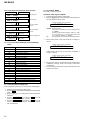
5. The display changes a shown below each time the
[DISPLAY] key is pressed.
XXX ***S##
item number
address
• Address & Adjusted Value Display
Remote commander LCD display
Remote commander LCD display
adjusted value
XXX ***J##
item number
jitter value
Remote commander LCD display
XXX ******##
item number
item title
adjusted valu
e
adjusted value
• Jitter Value & Adjusted Value Display
• Block/Bite Error Value & Adjusted Value Display
• Bite Error LPF Value & Adjusted Value Display *1)
• Focus Drive Value & Adjusted Value Display
• Item Title Display
XXX ***B##
item number
block/bite error value
Remote commander LCD display
adjusted value
XXX ***L##
item number
bite error LPF value
Remote commander LCD display
adjusted value
• CEMAX Value & Adjusted Value Display *1)
XXX ***C##
item number
CEMAX value
Remote commander LCD display
adjusted value
• ADIP Error Value & Adjusted Value Display
XXX ***A##
item number
ADIP error value
Remote commander LCD display
adjusted value
XXX ***F##
item number
focus drive voltage value
Remote commander LCD display
adjusted value
*1) It is skipped excluding the item number 5000 less than 8000.
6. To release the Manual mode, press the x key to return to the
Display Check mode.

15
MZ-DH10P
6-2. Error Message in The Overall Adjustment Mode
In the Overall Adjustment mode, if an error occurred, it displays as
following table.
Display Description
Close! Dose not close the lid
DfDis! Unsuitableness disc was inserted
NoChg! Does not finish the check of charge function yet
NotCD! Does not complete the CD Overall adjustment before the
MD1 Overall adjustment
NotM1! Does not complete the MD1 Overall adjustment
before the Hi-MD3 Overall adjustment
NotH3! Does not complete the Hi-MD3 Overall adjustment
before the Stray Light Offset Overall adjustment
****NG Error of item number “****”
7. SELF-DIAGNOSIS RESULT DISPLAY MODE
This set uses the self-diagnostic function system in which if an error
occurred during the recording or playing, the mechanism control
block and the power supply control block in the microcomputer
detect it and record its cause as history in the nonvolatile memory.
By checking this history in the test mode, you can analyze a fault
and determine its location.
Total recording time is recorded as a guideline of how long the
optical pick-up has been used, and by comparing it with the total
recording time at the time when an error occurred in the self-
diagnosis result display mode, you can determine when the error
occurred.
Clear the total recording time, if the optical pick-up was replaced.
7-1. Operation of The Self-Diagnosis Result Display
Mode
1. Enter the test mode (Display Check mode).
2. Press the
> key to activate the Self-Diagnosis Result Display
mode where the LCD displays as shown below.
Display of the remote commander
6. OVERALL ADJUSTMENT MODE
6-1. Operation of The Overall Adjustment Mode
1. Enter the test mode (Display Check mode).
2. Press the [VOL--] key to activate the Overall Adjustment mode
where the LCD displays as shown below.
Display of the remote commander
*** $$####
Overall Adjustment Mode
x
key
x
key
x
key
x
key
.
key
>
key
rotation
x
key
[DOWNLOAD]
key
[DISPLAY]
key
CD Overall Adjustment Mode
Optical Pick-up Operation
Check Mode
Stray Light Offset Overall
Adjustment Mode
Initialize The Adjustment Values
Hi-MD3 Overall Adjustment Mode
MD1 Overall Adjustment Mode
[VOL +]
key
[VOL --]
key
x
key
000 AdjF**
*** CD Run
*** MD1Run
*** HM3Run
*** OfsRun
000 OPChk
911 ResOK?
000 AdjF**
Disc mark:
Lit the inner segments: Completed the power supply adjustment.
Lit the outer segments: Completed the check of charge function.
“**”:
If “DF” or “FF” is displayed, it mean that completed the servo
overall adjustment.
3. To release the Overall Adjustment mode, press the x key and
return to the Display Check mode.
Flow of overall adjustment mode:
“***”: Error display code
“$$”: Error rivision history code
“####”: Addition information when error occurs
3. To r elease the Self-Diagnosis Result Display mode, press the x key
and return to the Display Check mode.

16
MZ-DH10P
“$$$$$$”:Pressed key name.
When remote commander key is pressed, display becomes
as “r$$$$$”.
When the jog dial is turned, it displays “JOG+ X” or “JOG-
X” (“X” is number of 1 to 3). If the jog dial is turned four
click, it displays “JOG+OK” or “JOG-OK”.
“##”:Key voltage of remote commander. (Hexadecimal number)
3. When all keys check is OK on the main unit, it displays as
follows.
Display of the remote commander
7-2. Error Code of The Self-Diagnosis Result Display
Mode
Error display code Description
000 No error
001 Attempt to access an abnormal address
002 High temperature detected
003 Focus error (no change)
004 Abnormal rotation of disc
005 Fault of disc discriminate
006 Error of access loop (no change)
007 Error of access loop (with change)
008 Could not read address
009 Focus error (with change)
012 Could not read data with SYNC
013 TOC address data error
032 Focus error, ABCD offset error
033 Tracking error, offset error
034 X1 tracking error, Tracking error, offset error
Error display code Addition information when error occurs
000 0000
001 Illegal cluster specified when error occurs
002 to 034 Total recording time when erroe occurs
7-3. Clear The Total Recording Time
After replacing the optical pick-up, clear the total recording time.
1. Enter the test mode (Display Check mode).
2. Press the > key to activate the Self-Diagnosis Result Display
mode.
3. Press the [VOL--] key once to display the total recording time
indication.
4. Press the + , u ENT key on the set or – key on the
remote commander and display “ClrOK?”.
5. Press the + , u ENT key on the set or – key on the
remote commander again to display “RecT 0” and clear the
total recording time.
Flow of Self-diagnosis Result Display mode operation:
The first error
[VOL +]
key
[VOL --]
key
The last error
One error before
the last
Two error before
the last
Total recording tim
e
[VOL +]
key
[VOL --]
key
[VOL +]
key
[VOL --]
key
[VOL +]
key
[VOL --]
key
[VOL +]
key
[VOL --]
key
*** 1 ####
*** N ####
*** N1####
*** N2####
*** R_####
110 $$$$$$ ##
888 SET OK ##
888 RMC OK ##
8. KEY CHECK MODE
This mode is used for key check.
Operation of The Key Check Mode
1. Enter the test mode (Display Check mode).
2. Press the [DISPLAY] key to activate the Key Check mode where
the LCD displays as shown below.
Display of the remote commander
When all keys check is OK on the remote commander, it
displays as follows.
Display of the remote commander
4. When all keys check are OK both the main unit and the remote
commander, it display backs to the Display Check mode
automatically.
5. To release the Key Check mode, open the lid and return to the
Display check mode.

17
MZ-DH10P
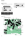
Procedure:
1. Connect the digital voltmeter to measuring point (refer to the
following table) and TP461 (GND).
2. Press the > key to change the item numberr to 2211.
3. Adjust with [VOL+]/[VOL--] keys so that the value of digital
voltmeter becomes specification value.
4. Press the + , u ENT key on the set or – key on the
remote commander to write the adjusted value.(Shifts to the
next item automatically)
5. Repeat adjustment from step 3 until item number 2233.
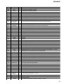
ItemNo. Display Specification value Measuring point
2211 211 VC1 ** 2.05V + 0.02V TP8003
2212 212 VC1H N ** 2.25V ± 0.01V TP8003
2213 213 VC2 ** 1.20V + 0.01V TP602
2214 214 DDC3 L ** 2.60V ± 0.015V TP913
2215 215 DDC3 H ** 3.10V ± 0.015V TP913
2216 216 REG1 L ** 2.32V ± 0.02V TP901
2217 217 REG1 H ** 3.02V ± 0.02V TP901
2218 218 REG2 1 ** 2.275V ± 0.01V TP509
2219 219 REG2 2 ** 2.480V ± 0.01V TP509
2221 221 REG2 3 ** 2.740V ± 0.01V TP509
2222 222 REG2 4 ** 2.985V ± 0.01V TP509
2223 223 REG3 ** 2.52V ± 0.02V TP516
2224 224 VREC 1 ** 0.89V ± 0.02V TP601
2225 225 VREC 2 ** 1.08V ± 0.02V TP601
2226 226 VREC 3 ** 1.52V ± 0.02V TP601
2227 227 VREC 4 ** 2.27V ± 0.02V TP601
2228 228 VREC 5 ** 2.97V ± 0.02V TP601
2229 229 VREC 6 ** 0.94V ± 0.02V TP601
2231 231 VREC 7 ** 1.28V ± 0.02V TP601
2232 232 VREC 8 ** 2.57V ± 0.02V TP601
2233 233 VREC 9 ** 2.57V ± 0.02V TP601
Note1: “**” is adjustment value (hexadecimal number).
Note2: Ground point of all measuring points is TP461.
Note3: Refer to page 18 for adjustment location.
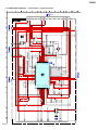
Table 3-3-1. PwrAdj Specifications
adjustment value (hexadecimal)
211 VC1 **
SECTION 5
ELECTRICAL ADJUSTMENTS
1. PRECAUTIONS FOR ADJUSTMENT
1. Adjustment must be done in the test mode only. After adjusting,
release the test mode. A key having no particular description
in the text, indicates a set key. Also, for the LCD display, the
LCD on the remote commander is shown.
2. Use the following tools and measuring instruments.
• Digital voltmeter
• Regulated dc power supply (two sets)
• Laser power meter
• CD adjustment disc TDYS-1 (Part No. : 4-963-646-01)
• MD1/HiMD1 hybrid adjustment disc MDW-74/GA2
(Part No. : J-2503-022-A)
• Hi-MD3 adjustment disc HMD1GSDJ
(Part No. : 8-892-388-38) *1
• Remote commander in accessories (with LCD)
• Battery charging stand and AC adapter in accessories
*1) Hi-MD3 adjustment disc (HMD1GSDJ) is consumable.
Therefore if it is used 400 times, exchange it for a new.
2. ADJUSTMENT SEQUENCE
Adjustment must be done with the following order.
Adjustment order:
1. Entering the test mode
2. Initialize the adjustment value
3. Power supply voltage adjustment
4. Charge function check
5. Laser power check
6. Setting the adjustment values
7. Servo Overall adjustment
8. Resume clear
9. Releasing the test mode
3. ADJUSTMENT OF THE EACH ITEM
3-1. Entering The Test Mode
Refer to the “SECTION 4. TEST MODE”. (See page 13)
3-2. Initialize The Adjustment Value
Procedure:
1. In the test mode (Display Check mode), press the [VOL--] key
to enter the Overall adjustment mode.
2. Press the [DOWNLOAD] key and display “911 ResOK?”.
3. Press the
+ , u ENT key on the set or – key on the
remote commander to display “911 Reset!” and initialize the
adjustment values.
4. Press the x key and back to Display Check mode.
3-3. Power Supply Voltage Adjustment
Adjustment must be done with the following order.
3-3-1. Setting
Procedure:
1. Apply the voltage of 3.7 V to the battery terminals, and enter
the test mode (Display Check mode).
2. Press the [VOL+] key to enter the Manual mode.
3. Press the [VOL+] key twice to display as follows.
Display of the remote commander
4. Press the > key once, press the [VOL+] key once, and press
the > key once again to display as follows.
Display of the remote commander
002 POWER
5. Repeat the next procedures (3-3-2. PwrAdj Adjustments), and
adjust all contents of “table 3-3-1. PwrAdj Specifications”.
3-3-2. PwrAdj adjustments
Repeat the following procedures and adjust all contents of “table 3-
3-1. PwrAdj Specifications”.
Example Display (Item No. 2211)
210 PwrAdj
Ver. 1.1

18
MZ-DH10P
2. Apply the voltage of 5 V to the TP453 and TP460 (GND).
3. Press the > key to change the item number to 2241.
4. Adjust with [VOL+]/[VOL--] keys so that the value of digital
voltmeter becomes specification value. (refer to “table 3-3-2.
VBsAdj Specifications”)
5. Press the + , u ENT key on the set or – key on the
remote commander to write the adjusted value.
6. Repeat adjustments to item number 2243 at the same manner
as step 4 to step 5.
ItemNo. Display Specification value Measuring point
2241 241 REG4 ** 1.13 V ± 0.01 V TP602
2242 242 REG5 ** 2.05 V + 0.02 V TP8003
2243 243 REG6 ** 3.30 V ± 0.01 V TP8007
Note1: “**” is adjustment value (hexadecimal number).
Note2: Ground point of all adjustment points is TP461.
Table 3-3-2. VBsAdj Specifications
3-3-3. VBsAdj adjustments
Procedure:
1. In the “3-3-2. PwrAdj Adjustments” completed status, display
as follows.
Display of the remote commander
7. Select the item number 2244, and turn off the power supply of
battery terminal.
8. Adjust with [VOL+]/[VOL--] keys so that the voltage of between
TP604 and TP461 (GND) becomes 4.10 V (− 0.02 V).
9. Press the + , u ENT key on the set or – key on the
remote commander to write the adjusted value.
10. Apply the voltage of 3.7 V to the battery terminal again.
11. Turn off the voltage of 5 V to the TP453 and TP460 (GND).
12. Press the x key three times and back to the Display Check
mode.
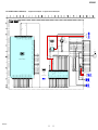
C255
C636
C629 R665
R634
R603
R647
R609
R644
R645
R632
R664
R843
C847
R876
R846
R879
R986
R813
C835
C817
C814
R839
R840
R854
R836
R834
C813
R835
C855
R994
R849
R871
R869
C851
R867 C810
C823
R801
R860
C852
C827
R837
R859
R830
R892
C891
R810
R828
R852
R858
C820
R845
C843
R756
R764
R757
C868
R878
C866
R630
R650
R619
R610
R633
R891
R895
R964
R966
C664
R961
C902
R898
R893
C892
R663
R643
C654
R355
R640
R657
C660
C153
C154
+
C254
+
C253
R651
C647
R153
R253
C639
C155
L152 L252
L601
FB357
FB353
FB354
FB355
F351
C659
C651
IC604
21
1
3
3
4
4
5
IC605
C658
+
C613
+
C612
+
C621
+
C615
+
C616
+
C653
+
C652
+
D603
KA
D602
KA
D615
AK
D963
AK
D962
AK
D614
AK
D604
K
A
D618
KA
Q607
C655
C601
C619
R833
C812
FB803
R759
C656
R701
R703
R704
R702
Q605
Q603
L605
L606
L951
L607
IC602
C874
+
C875
+
C818
+
L801
C880
C879
D871
KA
IC872
43
12
IC803
IC802
2
1
3
4
Q804
IC603
4
3
1
41
58
41
58
2
43
15
IC891
5
1
1
3
5
4
8
4
IC950
L702
L703
L704
L701
C959
C962
S431
BATTERY INSERT
DETECT
S893
OPEN/CLOSE
DETECT
S891-2
Hi-MD
PROTECT DETECT
S891-1
(PROTECT DETECT)
L907
L906
C940
+
C924
+
D904
K
A
D905
AK
D352
Q611
Q604
Q606
D801
AK
Q802
GDS
SDG
Q801
IC804
21
34
Q803
BCE
1
4
8
5
-2
-1
2C1B 1E
2E 2B 1C
2C1B1E
2E2B1C
D
D
S
D
D
G
D
D
S
D
D
G
2B
1C
2E
1E
1B
2C
48 38 37 1 2 3 5 4
22 30 29 21 6 7 18 8
24 32 31 23 44 19 43 41
25 46 33 26 20 45 42 40
27 34 35 28 12 11 9 10
47 36 39 17 16 15 13 14
∗
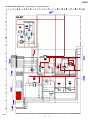
TP602 TP601 TP8003
TP800
7
TP509
TP51
6
TP453
TP461
(GND)
TP46
0
(GND)
TP604
TP901
TP913
– MAIN BOARD (Component Side) –
Adjustment Location:
240 VBsAdj

19
MZ-DH10P
5. Press the > key three times to select the item number 9111
and display as follows.
Display of the remote commander
6. And > key once again to select the item number 2251 and
display “251 ChgChk **” on the LCD of remote commander.
7. Press the + , u ENT key on the set or – key on the
remote commander confirm that “ADJ OK” is displayed.
8. Press the x key four times and back to the Display Check
mode.
9. Cut the power supply and remove the resistor that connected
to the battery terminals.
3-5. Laser Power Check
Procedure:
1. Enter the test mode (Display Check mode).
2. Press the [VOL+] key to enter the Manual mode.
3. Open the lid and press the . key continuously until the
optical pick-up moves to the most inward track.
4. Press the [VOL--] key once to display as follows.
Display of the remote commander
3-4. Charge Function Check
Note1: When perform this check, don’t apply a voltage to battery terminals.
Note2: Be sure to disconnect the AC adapter when connecting the resistors.
Doing so with the power supply connected causes a trouble.
Procedure:
1. Connect the 10 ohms resistor (more than 3 watts) to battery
terminals.
2. Connect the AC adapter to the battery charging stand in
accessories and set the main unit.
3. Enter the test mode (Display Check mode).
4. Press the [VOL+] key to enter the Manual mode.
5. Press the [VOL+] key twice, press the > key once, press the
[VOL+] key once, press the > key once, press the [VOL+]
key twice to display as follows.
Display of the remote commander
3-6. Setting The Adjustment Values
3-6-1. Hi-MD3 setting
Preparation:
1. Perform calculation every item based on the data given by the
Hi-MD3 adjustment disc by referring to the following table.
(Round off the value in decimal place)
2. Convert the calculated value into hexadecimal number.
Note: The Hi-MD3 adjustment parameters vary depending on the disc,
and therefore use the parameters of the disc used when performing
the adjustment.
Item No. Calculating formula (*3)
0211 Pr_nominal / 0.05
(*1) Por / 0.05
0212 Kr × (−100)
0213 Pw_nominal / 0.05
(*2) Ppw / 0.05
0214 Kw × (−100)
0215 Prmin / 0.05
0216 Pwmin / 0.05
*1) If the “Pr_nominal” value is indicated, use the “Pr_nominal” value
and not used “Por” value.
*2) If the “Pw_nominal” value is indicated, use the “Pw_nominal” value
and not used “Ppw” value.
*3) Round off after the decimal point.
Table 3-6-1. Hi-MD3 adjustment parameter
Example of Calculation:
Item No. Parameter
Result
Decimal Hexadecimal
0211 Pr_nominal 2.48 mW 50 32h
0212 Kr −0.3 %/°C30 1Eh
0213 Pw_nominal 7.35 mW 147 93h
0214 Kw −0.4 %/°C40 28h
0215 Prmin 1.9 mW 38 26h
0216 Pwmin 5.8 mW 116 74h
Procedure:
1. Enter the test mode (Display Check mode).
2. Press the [VOL+] key to enter the Manual mode.
3. Press the > key once, press the [VOL+] key once, and press
the > key once again to display as follows.
Display of the remote commander
250 ChrgLi
009 DESIGN
111 LrefPw **
210 DiscPr
6. Set the laser power meter so that the laser beam from the optical
pick-up aims at the objective lens of laser power meter at right
angle. (Confirm it with the disc not inserted)
7. Confirm that the value of laser power meter is 0.860 mW ±
19.2%.
8. Press the > key to select the item number 9112.
9. Confirm that the value of laser power meter is 0.763 mW ±
18.2%.
10. Press the > key to select the item number 9113.
11. Confirm that the value of laser power meter is 6.87 mW ±
12%.
12. Press the x key four times and back to the Display Check
mode.
4. Press the > key once to select the item number 0211.
5. Adjust with [VOL+]/[VOL--] keys so that the adjustment value
of LCD becomes calculated value.
6. Press the + , u ENT key on the set or – key on the
remote commander to write the adjusted value.
7. Press the > key to next item.
8. Repeat adjustment from step 4 until item number 0216.

20
MZ-DH10P
3-6-2. Destination setting
1. Enter the test mode (Display Check mode).
2. Press the [VOL+] key to enter the Manual mode.
3. Press the > key five time to select the item number 0113
and display as follows.
Display of the remote commander
adjustment value (hexadecimal
)
113 DistFL **
4. Press the [VOL+]/[VOL--] key and set the according value to
each destination referring to the following table.
5. Press the + , u ENT key on the set or – key on the
remote commander to write the adjusted value.
6. Press the > key to select the item number 0114.
7. Repeat adjustment from step 3.
8. Press the x key four times and back to the Display Check
mode.
Destination
Setting value
Item No. 0113 Item No. 0114
US 28 80
AEP and UK A0 80
Chinese and Tourist 24 80
Table 3-6-2. Destination Setting
3-6-3. Other setting
Procedure:
1. Enter the test mode (Display Check mode).
2. Press the [VOL+] key to enter the Manual mode.
3. Press the [VOL+] key once and press the
> key five time to
select the item number 1113 and display as follows.
Display of the remote commander
15. Press the + , u ENT key on the set or – key on the
remote commander to write the adjusted value.
16. Press the x key four times and back to the Display Check
mode.
3-7. Servo Overall Adjustment
Note1: Be sure to adjustment so that the set is horizontal and the LCD is
upside. Unless performed in that state, it is not adjusted correctly.
Note2: If NG is displayed in the middle of this adjustments, perform “3-2.
Initialize The Adjustment Value” and “3-6. Setting The Adjustment
Values” again, then retry this adjustments from step 1.
Procedure:
1. Enter the test mode (Display Check mode).
2. Press the [VOL--] key to enter the Overall Adjustment mode.
3. Insert the CD adjustment disc (TDYS-1).
4. Put the main unit horizontal so that the LCD becomes upside,
and press the . key.
5. Wait until “CD OK” is displayed on the LCD.
6. Insert the MD1/HiMD1 hybrid adjustment disc
(MDW-74/GA2).
7. Put the main unit horizontal so that the LCD becomes upside,
and press the > key.
8. Wait until “MD1 OK” is displayed on the LCD.
9. Insert the Hi-MD3 adjustment disc (HMD1GSDJ).
10. Put the main unit horizontal so that the LCD becomes upside,
and press the [VOL+] key.
11. Wait until “HMD3OK” is displayed on the LCD.
12. Eject the disc and close the lid.
13. Put the main unit horizontal so that the LCD becomes upside,
and press the [VOL--] key.
14. Wait until “OfstOK” is displayed on the LCD.
15. Press the x key and back to the Display Check mode.
3-8. Resume Clear
Procedure:
1. Enter the test mode (Display Check mode).
2. Press the [VOL+] key to enter the Manual mode.
3. Press the [VOL+] key once, press the
> key once, press the
[VOL--] key once, press the > key once, and press the [VOL+]
key twice, press the > key three times to select the item
number 1933.
4. Press the + , u ENT key on the set or – key on the
remote commander to resume clear.
5. Press the x key four times and back to the Display Check
mode.
3-9. Releasing The Test Mode
Refer to the “SECTION 4. TEST MODE”. (See page 13)
4. Adjust with [VOL+]/[VOL--] keys so that the adjustment value
of “**” on the LCD becomes “1A”.
5. Press the + , u ENT key on the set or – key on the
remote commander to write the adjusted value. ($$ blinks and
disc mark rotates on the LCD)
6. Adjust with [VOL+]/[VOL--] keys so that the adjustment value
of “$$”on the LCD becomes “20”.
7. Press the + , u ENT key on the set or – key on the
remote commander to write the adjusted value. (## blinks and
disc mark rotates on the LCD)
8. Adjust with [VOL+]/[VOL--] keys so that the adjustment value
of “##”on the LCD becomes“ 5E”.
9. Press the + , u ENT key on the set or – key on the
remote commander to write the adjusted value.
10. Press the [VOL+] key once to change the adjustment value of
“**” on the LCD into “1B”.
11. Press the + , u ENT key on the set or – key on the
remote commander to write the adjusted value. ($$ blinks and
disc mark rotates on the LCD)
12. Adjust with [VOL+]/[VOL--] keys so that the adjustment value
of “$$”on the LCD becomes “F1”.
13. Press the + , u ENT key on the set or – key on the
remote commander to write the adjusted value. (## blinks and
disc mark rotates on the LCD)
14. Adjust with [VOL+]/[VOL--] keys so that the adjustment value
of “##”on the LCD becomes “1A”.
adjustment value (hexadecimal)
113 SS**$$##
Ver. 1.2
Page is loading ...
Page is loading ...
Page is loading ...
Page is loading ...
Page is loading ...
Page is loading ...
Page is loading ...
Page is loading ...
Page is loading ...
Page is loading ...
Page is loading ...
Page is loading ...
Page is loading ...
Page is loading ...
Page is loading ...
Page is loading ...
Page is loading ...
Page is loading ...
Page is loading ...
Page is loading ...
Page is loading ...
Page is loading ...
Page is loading ...
Page is loading ...
Page is loading ...
Page is loading ...
Page is loading ...
Page is loading ...
Page is loading ...
Page is loading ...
Page is loading ...
Page is loading ...
Page is loading ...
Page is loading ...
Page is loading ...
Page is loading ...
Page is loading ...
Page is loading ...
Page is loading ...
Page is loading ...
Page is loading ...
Page is loading ...
Page is loading ...
Page is loading ...
-
 1
1
-
 2
2
-
 3
3
-
 4
4
-
 5
5
-
 6
6
-
 7
7
-
 8
8
-
 9
9
-
 10
10
-
 11
11
-
 12
12
-
 13
13
-
 14
14
-
 15
15
-
 16
16
-
 17
17
-
 18
18
-
 19
19
-
 20
20
-
 21
21
-
 22
22
-
 23
23
-
 24
24
-
 25
25
-
 26
26
-
 27
27
-
 28
28
-
 29
29
-
 30
30
-
 31
31
-
 32
32
-
 33
33
-
 34
34
-
 35
35
-
 36
36
-
 37
37
-
 38
38
-
 39
39
-
 40
40
-
 41
41
-
 42
42
-
 43
43
-
 44
44
-
 45
45
-
 46
46
-
 47
47
-
 48
48
-
 49
49
-
 50
50
-
 51
51
-
 52
52
-
 53
53
-
 54
54
-
 55
55
-
 56
56
-
 57
57
-
 58
58
-
 59
59
-
 60
60
-
 61
61
-
 62
62
-
 63
63
-
 64
64


Sony sony mz-dh10p User manual
- Category
- Car audio amplifiers
- Type
- User manual
- This manual is also suitable for
Ask a question and I''ll find the answer in the document
Finding information in a document is now easier with AI
Related papers
-
Sony MZ-DH10P Hi-MD Music Transfer Version 1 for Mac (User Manual) Owner's manual
-
-
Sony Hi-MD WALKMAN MZ-RH1 User manual
-
-
-
-
-
Sony MZ-RH910 User manual
-
Sony MZ-NH1 User manual
-
Other documents
-
Aiwa JAX-N55 User manual
-
Panasonic SJ-MR230DGK User manual
-
-
 BSS Audio FCS-926 User manual
-
LG CD-372A User manual
-
Sony Ericsson CDX-CA860X User manual
-
Zenith ZH-T202SF Series User manual
-
Sanyo VPC-CA8GXBK User manual
-
Telex BTR-200 Series User manual
-
AOC HP L1906 User manual
