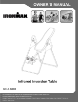
The specifications of this product may vary from this photo and are subject to change without notice.
IRONMAN, IRONMAN TRIATHLON and M-DOT are registered trademarks of World Triathlon Corporation.
This product is licensed by the World Triathlon Corporation.
OWNER’S MANUAL
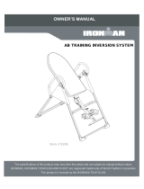
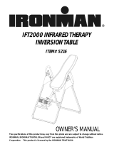
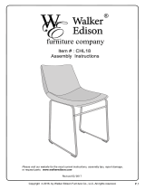
iControl Disk Brake
Inversion Table
Item#5610

5610.2‐050515

SERVICE-------------------------------------------------------------------- 2
IMPORTANT SAFETY INSTRUCTIONS--------------------------- 3
LABELPLACEMENT----------------------------------------------------- 5
OVERVIEW DRAWING------------------------------------------------- 6
PART LIST----------------------------------------------------------------- 8
HARDWARE LIST & TOOLS----------------------------------------- 10
ASSEMBLY----------------------------------------------------------------11
HOW TO USE-------------------------------------------------------------18
OPERATION AND ADJUSTMENTS-------------------------------- 20
STORAGE----------------------------------------------------------------- 22
WARM UP----------------------------------------------------------------- 23
WARRANTY-------------------------------------------------------------- 24
FAX FORM---------------------------------------------------------------- 25
TABLEOFCONTENTS
1

IMPORTANT: FOR NORTH AMERICA ONLY
To request product service and order
replacement parts, please call our
customer service department at:
1-844-641-7922
Daily 8:00 AM-5:00 PM Pacific Standard Time,
or email us at: service@paradigmhw.com
Please visit our website at www.paradigmhw.com.
Please have the following information ready when requesting for service:
Your name
Phone number
Model number
Serial number
Part number
Proof of Purchase
*Before returning this product to the store please contact
customer service at the contact number.
Paradigm Health & Wellness, Inc.
1189 Jellick Ave,
City of Industry, CA 91748, USA
SERVICE
2

This inversion table was designed and built for optimum safety. However, certain precautions
apply whenever you operate the exercise equipment. Be sure to read the entire manual
before assembling and operating this equipment. When using an appliance, basic precautions
should always be followed, including the following:
WARNING - To reduce the risk of injury to persons:
1. Consult your physician or other health care professionals before using the inversion
table.
2. Use this appliance only for its intended use as described in this manual.
Do not use attachments not recommended by the manufacturer.
3. Never operate this appliance if it is damaged, if it is not working properly, if it has been
dropped or damaged. Return the appliance to a service center for examination and
repair.
4. Do not use outdoors.
5. Do not exceed the maximum rated weight (load) and maximum rated height of the user.
6. For Household Use Only.
7. Always wear proper exercise apparel when using the equipment.
8. If any time you feel faint, light-headed or dizziness while operating the equipment, stop
exercise immediately. You should also stop exercising if you are experiencing pain or
pressure.
9. Only one person should use the equipment at a time.
10. Make sure your equipment is correctly assembled before you use it. Be sure all screws,
nuts, and bolts are tightened prior to use.
11. Watch your body: come up slowly, dizziness after a session means you came up too fast.
Wait a while after eating before using the inversion table. If you get nauseous, come up
as soon as you feel queasy.
12. Always use this equipment on a clear and level surface. Do not use near water.
13. Close supervision is necessary when this inversion table is used by, on, or near children,
invalids, or disabled persons.
14. Never drop on insert any object into any opening.
15.
WARNING: ALWAYS HOLD ON TO THE SAFETY HANDLES AND GO BACK
SLOWLY WHEN INVERTING. FAILURE TO COMPLY COULD RESULT IN SERIOUS
BODLIY INJURY.
16.
WARNING: To reduce the risk of personal injury, read and understand all the
instructions before using the inversion table.
17.
WARNING: Risk of personal injury – Do not allow children to use this machine.
18. WARNING: Risk of personal injury – Keep children away from machine while in
use.
19.
WARNING: Risk of personal injury – Do not grab brake level for getting up, use
handle bar instead.
IMPORTANTSAFETYINSTRUCTIONS
3

20. WARNING - Risk of personal injury - Keep body parts, hair, loose clothing and
jewelry clear of all moving parts.
NOTE: Maximum user weight for this product is 300 lbs (136 kgs.)
Maximum Rated Height for this product is 6’6”/198cm.
WARNING: Before using this equipment you should consult with your personal
physician to see if inversion equipment is appropriate for you.
Do not use this
equipment without your physician's approval. Do not use this equipment if you have
any of the following conditions or ailments:
Extreme obesity
Glaucoma, retinal detachment or conjunctivitis
Pregnancy
Spinal injury, Cerebral Sclerosis, or acutely swollen joints
Middle ear infection
High blood pressure, Hypertension, Recent stroke or Transient
is chemic attack
Heart or circulatory disorders for which you are being treated.
Hiatus hernia or Ventral hernia
Bone weaknesses including Osteoporosis, Unhealed fractures,
Modularly pins, or surgically implanted orthopedic supports.
Use of anti-coagulants including Aspirin in high doses.
SAVE THESE INSTRUCTIONS
IMPORTANTSAFETYINSTRUCTIONS
4

LABELPLACEMENT
5

60
57
3
4
45
59
46
19
24
54
29
36
46
14
13
38
15
13
46
60
50
43
52
48
37
46
12
63
21
33
34
47
60
57
22
28
54
55
45
58
46
59
46
14
29
36
32
2
26
27
51
53
27
51
53
1
20
49
27
51
49
27
51
13
38
61
13
15
13
15
13
38
67
67
13
38
13
15
67
67
43
62
62
OVERVIEWDRAWING
6

35
10
65
68
13
64
68
8
44
6
9
39
7
31
25
11
17
40
16
13
13
15
23
42
41
27
27
56
11
5
25
7
66
13
15
13
13
15
40
27
27
16
64
30
18
41
64
64
31
31
31
7
7
25
25
OVERVIEWDRAWING
7

No.
Description
Q'ty No. Description
Q'ty
1
Front Frame
1
29 Handlebar
2
2
Cup Holder
1
30 Knob Ø45x3/8”x19L
1
3
Rear Frame
1
31 Steel Bracket
4
4
Cup Holder Rotation Cap
1
32 Bolt M6x30
1
5
Rectangle End Cap
□
33.4x33.4xt2
1
33
Lock Mechanism
1
6
Front Rod
1
34 Lock Handle Plastic Bar
1
7
Rubber Heel Holder
4
35 Foam Bed
1
8
Adjustable Boom
1
36 Handlebar Foam Grip
2
9
Rear Rod
1
37 Metal Sleeve
1
10
Bed Frame
1
38 Bolt M8x45
4
11
Foot bar End Cap 20x60xt1.5
2
39 Foot Bar
1
12
Right Pivot Arm
1
40
Hex Bolt M6x47
1
13
Washer Ø8.5xØ20xt1.5
18
41
Square End Cap 38x38xt2
2
14
Curve Washer
Ø8.5xØ16xt2.0 2
42
Spring Latch Ø4x32
1
15
Lock Nut M8 (Galvanize)
8
43 Bolt M8x12
2
16
Lock Nut M6
2
44 Height Scale
1
17
Spring Knob
1
45
Washer Ø8.5xØ24x2mm
2
18
Boom Spring Knob
1
46 Bolt M8x20
6
19
Left Pivot Arm
1
47 Brake Bracket
1
20
Rubber Pad
1
48 Upper Plastic Cover
1
21
Right Brake Pad I
1
49 Rear Foot Cap
2
22
Right Brake Pad I I
1
50 Bolt M6x25
1
23
Spring Ø10xØ1x110Lx85N
1
51 Bolt M6x15
4
24
Rotor Cover
1
52 Lower Plastic Cover
1
25
Round End Cap
Ø22x1.5
4
53 Front Foot Cap
2
26
Spring
Ø13xt2x(230)
1
54
Pivot Arm Rotation Cap I
Ø60xØ19.5x18
2
27
Washer Ø12xØ6.5x1.0
8
55
Pivot Arm Rotation Cap II
Ø60xØ19.5x21
1
28
Fixed Plate
1
56 Bolt M8x50 2
PARTLIST
8

No.
Description
Q'ty No. Description
Q'ty
57
Washer Ø4.3xØ9xt0.3
4
63 Bolt M4x20
2
58
Round Cap
1
64
Rectangle End Cap
□
25x50xt1.5
4
59
Spring Washer Ø8.1xØ12.3x2.1 1
65
Upper Bed Frame End cap
□
50x50xt2
1
60
Screw ST3.5x10
9
66 Lower Bed Frame Bushing
2
61
Locking Pin
1
67
Cap
₵
27x13.5
4
62
Brake Strap
2 68 Bolt M8x40 4
9
PARTLIST

(13) Washer
10 PCS
(15) Lock Nut
6 PCS
(16) Lock Nut
2 PCS
(27) Washer
8 PCS
(14) Curve Washer
2 PCS
(38) Bolt
2 PCS
(40) Hex Bolt
2 PCS
(43) Bolt
2 PCS
(46) Bolt
4 PCS
(56) Bolt
2 PCS
(67) Cap
4 PCS
(51) Bolt
4 PCS
(63) Bolt
2 PCS
(61) Locking Pin
1 PC
Hex Wrench
2 PCS
Phillips Screwdriver
1 PC
Allen Wrench #5
1 PC
Allen Wrench #6
1 PC
HARDWARELIST&TOOLS
10

The product weighs more than 44lbs / 20kgs and should
be assembled and moved by two or more people.
Phillips Screwdriver
1 PC
3
49
27
51
61
67
67
15
1
49
27
51
53
27
51
53
27
51
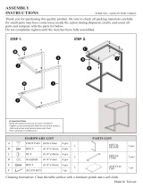
(27) Washer
4 PCS
(67) Cap
2 PCS
(51) Bolt
4 PCS
(61) Locking Pin
1 PC
Step 1.
Attach Front Foot Cap (53) and Rear Foot Cap (49) to the Feet of the Front Frame (1) and Rear
Frame (3); tighten Bolts (51) and Washers (27) with the Phillips Screwdriver Provide.
Unfold the Frame fully; inset Locking Pin (61) into whole of the joint of the Front and Rear Frames
(1,3). Attach the Cap (67) to the Lock Nut (15).
ASSEMBLY
Hardware:
11
Tool:

(13) Washer
2 PCS
(15) Lock Nut
2 PCS
(43) Bolt
2 PCS
(46) Bolt
2 PCS
A
llen Wrench #5
1 PC
A
llen Wrench #6
1 PC
10
35
30
12
12
46
43
15
13
43
19
46
3
1
15
13
#6
#5
.
Step 2.
Attach the Bed Frame (10) onto the Right Pivot Arm (12) and Left Pivot Arm (19) by using two Lock
Nuts (15), two Bolts (46) and two Washers (13);
Tighten Bolts (43) with #5 Allen Wrench provided.
Tighten Bolts (46) and Lock Nuts (15) with #6 Allen Wrench and Hex Wrench provided.
Install the Knob (30) onto the Bed Frame (10).
ASSEMBLY
12
Hardware:
Tool:
Hex Wrench
2 PCS

29
46
14
#6
13
34
33
1
2
4
29
46
14
63
13
38
15
13
67
38
13
15
67
3
#6
(13) Washer
4 PCS
(15) Lock Nut
2 PCS
(14) Curve Washer
2 PCS
(38) Bolt
2 PCS
(67) Cap
2 PCS
(46) Bolt
2 PCS
(63) Bolt
2 PCS
Step 3.
Attach both Handlebars (29) onto Rear Frame (3) with four Washers (13), two Curve Washer (14),
two Lock Nuts (15), two Bolts (38) and two Bolts (46).
Tighten Bolts (46) with #6 Allen Wrench provided.
Tighten Bolts (38) and Lock Nuts (15) with #6 Allen Wrench and Hex Wrench provided, attach
the Caps (67) to the Lock Nuts (15).
Install the Cup Holder (2) to the Cup Holder Rotation Cap (4).
Install the Lock Handle Plastic Bar (34) onto the Lock Mechanism (33) and secure with Bolts (63).
Tighten the Bolts (63) with the Phillips Screwdriver provided.
ASSEMBLY
13
Hardware:
Tool:
A
llen Wrench #5
1 PC
A
llen Wrench #6
1 PC
Hex Wrench
2 PCS
Phillips Screwdriver
1 PC

31
9
8
17
16
40
27
27
41
7
7
31
AB
(16) Lock Nut
1 PC
(27) Washer
2 PCS
(40) Hex Bolt
1 PC
Step 4.
Remove the Square End Cap (41) on the back of square bracket of the Adjustable Boom (8);
Slide the Rear Rod (9) through the large round hole on the side of Adjustable Boom (8), and secure
the Rear Rod (9) on the Adjustable Boom (8) with one Hex Bolt (40), two Washers (27) and one Lock
Nut (16).
Tighten the Bolt, Washers and the Lock Nut with two Hex Wrenches provided.
Unite one Steel Bracket (31) and one Rubber Heel Holder (7); slide them onto one end of the
Rear Rod (9) until the lock tooth is wedged into the slot in the Rear Rod (9). Note: Make sure the lock
teeth are wedged into the slots in the Rear Rod (9) as shown in small figures A and B before use.
Attach the Spring Knob (17) onto the Adjustable Boom (8).
ASSEMBLY
14
Hardware:
Tool:
Hex Wrench
2 PCS

6
7
31
7
31
(13) Washer
4 PCS
(15) Lock Nut
2 PCS
(56) Bolt
2 PCS
Step 5.
Slide the Foot Bar (39) into the bottom of the Adjustable Boom (8) and align two of the holes on the
Foot Bar (39) with two holes on the Adjustable Boom (8). Secure the Foot Bar (39) in place using
two Bolts (56), two Lock Nuts (15) and four Washers (13).
Tighten Bolts and Lock Nuts with the #6 Allen Wrench and Hex Wrench provided.
15
ASSEMBLY
Hardware:
#6
39
56
13
13
15
8
A
llen Wrench #6
1 PC
Hex Wrench
2 PCS
Tool:
Step 6.
Install Steel Bracket (31) and one Rubber Heel
Holder (7) onto the Front Rod (6).
NOTE: Make sure the lock teeth are wedged into the
slots in the Front Rod (6) to lock the Steel
Brackets (31) in place before use.

17
6
23
8
6
8
41
6
23
2
1
23
27
16
27
40
40
16
27
27
(16) Lock Nut
1 PC
(27) Washer
2 PCS
(40) Hex Bolt
1 PC
ASSEMBLY
Step 7.
Pull up Spring Knob (17) and insert the Front Rod
(6) into the Adjustable Boom (8).
Insert the Front Rod (6) all the way in, pull the
plastic string through.
Pull the string as you insert the Hex Bolt (40) with a
Washer (27) through the Spring (23). Secure with a
Washer (27) and a Lock Nut (16).
Tight the Bolt (40), Washers (27) and the Lock Nut
(16) with two Hex Wrenches provided.
Attach the Square End Cap (41) onto the
Adjustable Boom (8).
16
Hardware:

30
8
18
10
Step 8.
Loosen the Knob (30). Pull the Boom Spring Knob (18) and slide the Adjustable Boom (8) in.
Slide the Adjustable Boom (8) up to be desired height. Release the Boom Spring Knob (18) and
make sure it “pops” into the hole. Tighten the Knob (30) for additional safety.
ASSEMBLY
17

Dismounting the table
Boom Spring Knob
Knob
A
djustable
Boom
1
Spring Knob
Ankle Pad
2
1
Spring Knob
Ankle Pad
2
Set the Adjustable Boom to your height
Turn Knob counter-clockwise to loosen the
Adjustable Boom.
Pull Boom Spring Knob as you adjust the
Adjustable Boom to desired height.
Turn Knob clockwise to de-rattle the
Adjustable Boom.
Note: When you invert, readjust the height adjustment
Boom up if the bed doesn’t rotate.
Adjust the height adjustment boom down if the bed rotates too fast.
Mounting the table
HOWTOUSE
Make sure the Lever is at
LOCK position.
Pull the Spring Knob to unlock, allow the Ankle Pads
to press against your ankles. Make sure the Spring
Knob locks into the hole.
Wearing shoes will help ankles stay more secure.
Make sure the Lever is at
LOCK position.
Pull the Spring Knob.
Press Ankle Pads forward.
18
Page is loading ...
Page is loading ...
Page is loading ...
Page is loading ...
Page is loading ...
Page is loading ...
Page is loading ...
/