Sentiotec PRO-B2 Sauna Control PRO B User manual
- Type
- User manual

Home » sentiotec » sentiotec PRO-B2 Sauna Control PRO B User Manual
new function „Door sensor“
Supplement / change to the operating instructions:
PRO-B2 /1-015-455 , PRO-B3 /1-015-457 Version 12/21
Contents
1 PRO-B2 Sauna Control PRO B
2 Electrical connection
3 Starting up
4 Operation
5 About this instruction manual
6 Important information for your safety
.
7 Product description
8 Installation
9 Electrical connection
10 Performing tests
11 Connection diagram
12 Starting-up
13 Operation
14 Cleaning and maintenance
15 Disposal
16 Troubleshooting
17 Technical data
18 Documents / Resources
18.1 References
19 Related Posts
PRO-B2 Sauna Control PRO B
sentiotec PRO-B2 Sauna Control PRO B User Manual
Manuals+ — User Manuals Simplified.

The new function ensures optimal door monitoring for remote control!
Optionale accessories: Door sensor home SAB00103 / 1-052-723
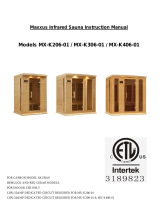
Electrical connection
Installing heater sensor (clamp red wires at STB) Connecting safety device or NEW connecting door sensor
Starting up
Remote start release:
As standard the function selection switch is in the OFF position.
The remote star is operated using „Standby for remote control“.
If you want to enable the remote start output for various devices (e.g. coinoperated unit, remote start system),
set the function selection switch 4 in the ON position

Activate door sensor at Pro B2
1. Open the technician menu (press at the same time: ON/OFF button, preset time button and the lower bottom
knob)
► In the top display „SdO“ appears
► In the bottom display „SAFE“ appears (= standard setting)
2. Turn the lower knob to the right
► In the lower display “door“ appears
3. Exiting the technician menu (Longpress on the lower knob)
Activate door sensor at Pro B3
1. Open the technician menu (press at the same time: ON/OFF button, preset time button and the lower bottom
knob)
► In the top display „dry“ appears
► In the bottom display „t60“ appears
2. Turn the lower buttom (Selection 0 – 60; 0 = post-drying progamm off , 60 = maximum runtime in minutes)
3. Press the lower knob
► In the top display „SdO“ appears
► In the bottom display „SAFE“ appears (= standard setting)
4. Turn the lower knob to the right

► In the lower display “door“ appears
5. Exiting the technician menu (Longpress on the lower knob)
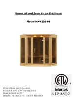
Operation
Activating „Standby for remote operation“ with door sensor Press the ON/OFF switch, to switch on the sauna
control unit.
Press the lower knob (= Temperature selector) for three seconds (=Longpress)
► A countdown of 30 seconds is shown in the lower display. During this time, the door can be opened/ closed as
often as you like. After the countdown has expired, the door must be closed!
► The remote start indicator starts flashing.
► The sauna control is now ready to be started and stopped once via a remote start signal = Mode „Standby for
remote operation“
Door is opened – warning „door“ appears in the display
– at mode „Standby for remote operation“:
To continue the mode, the door must be closed and the warning must be acknowledged with a long press on the
lower rotary control.
► The countdown (30 sec.) is shown again in the lower display.
– in operation or enable remot start output (for coinoperated unit or door sensor system):
The acknowledgment takes place automatically when the door is closed.
Sauna control unit
PRO B2
INSTRUCTIONS FOR INSTALLATION AND USE
PRO-B2 / 1-015-455
About this instruction manual
Read these instructions for installation and use carefully and keep them within reach of the sauna control unit.

This ensures that you can refer to information regarding your safety and regarding operation at any time.
These installation and operating instructions can also be found in the downloads section of our website:
www.sentiotec.com/downloads.
Symbols used for warning notices
In these instructions for installation and use, a warning notice located next to an activity indicates that this activity
poses a risk. Always observe the warning notices. This prevents damage to property and injuries, which in the
worst case may be fatal.
The warning notices contain keywords, which have the following meanings:
DANGER!
Serious or fatal injury will occur if this warning notice is not observed.
WARNING!
Serious or fatal injury can occur if this warning notice is not observed.
CAUTION!
Minor injuries can occur if this warning notice is not observed.
ATTENTION!
This keyword is a warning that damage to property can occur.
Other symbols
This symbol indicates tips and useful information.
Important information for your safety .
The sauna control unit Pro B2 has been produced in accordance with the applicable safety regulations for
technical units. However, hazards may occur during use. Therefore adhere to the following safety information and
the specific warning notices in the individual chapters. Also observe the safety information for the devices
connected.
2.1. Intended use
The sauna control unit Pro B2 is used exclusively for operating and controlling the sauna functions in accordance
with the technical data. The sauna control unit Pro B2 may only be used for operating and controlling a sauna
heater which has been certified as satisfying the combustion test described in paragraph 19.101 of EN 603352-
53. If the heater does not meet this requirement, an appropriate safety precaution must be taken (for example:
safety shut-off, see 5.6 on page 16). The sauna control unit Pro B2 may only be used for operating and controlling
3 heating circuits with a maximum heating capacity of 3.5 kW per heating circuit.
Any use exceeding this scope is considered improper use. Improper use can result in damage to the product, in
severe injuries or death.
2.2. Safety information for the installer
Installation may only be performed by a qualified electrician or similarly qualified person.
Work on the sauna control unit may only be performed when the power has been disconnected.
An all-pole disconnecting device with full cut-off compliant with overvoltage category III must be fitted on-site.
The sauna control unit must be installed outside the sauna room at a height of approx. 1.70 m or in accordance
with the recommendation issued by the sauna manufacturer. The ambient temperature must be within a range
spanning -10 °C to +40 °C.
The heater sensor must be attached in a way that it is not affected by a flow of air.
The heater supply cable must have a minimum cross-section of 2.5 mm 2 and be temperature resistant up to
150 °C.
Also comply with the regulations applicable at the installation location.
For your own safety, consult your supplier in the event of problems that are not explained in sufficient detail in

the installation instructions.
2.3. Safety information for the user
The sauna control unit must not be used by children under 8 years old.
The sauna control unit may only be used by children above 8 years old, by persons with limited psychological,
sensory or mental capabilities or by persons with lack of experience/knowledge: – When they are supervised. –
When they have been shown how to use the device safely and are aware of the hazards that could occur.
Children must not play with the sauna control unit.
Children under 14 years of age may only clean the sauna control unit if they are supervised.
For health reasons, do not use the sauna when under the influence of alcohol, medication or drugs.
Make sure that no flammable objects have been placed on the sauna heater before the sauna control unit is
switched on.
Make sure that no flammable objects have been placed on the heater before activating the preset time function
or the stand-by mode for the remote start.
For your own safety, consult your supplier in the event of problems that are not described in sufficient detail in
the operating instructions.
Product description
3.1. Scope of delivery
Sauna control unit
Heater sensor with integrated excess temperature fuse
Sensor wires
Installation material
3.2. Optional accessories
Bench sensor (item number: O-F2)
Power booster (item number: O-S2-18 / O-S2-30)
Safety shut-off (item number: SFE-xxxxx)
pronet web server (item number: PRO-NET)
3.3. Product functions
The sauna control unit Pro B2 features the following functions:
Regulation of sauna heaters with a heating output of up to 10.5 kW in the temperature range spanning 30 °C to
110 °C.
A power booster allows the maximum contact rating to be increased from 10.5 kW to 18 kW or 30 kW.
Remote start function
Preset time function (up to 24 hours)
Automatic heating period limiter The sauna control unit shuts down automatically after the maximum heating

period for safety reasons. The maximum heating period can be set to 6 h, 12 h, 18 h or 24 h.
Excess temperature fuse The excess temperature fuse is installed in the housing for the heater sensor. Should
the sauna heater continue heating after reaching the preferred temperature due to a defect, the excess
temperature fuse switches the sauna heater off at a temperature of approx. 139 °C.
3.4. Sensor operating modes
The sauna control unit can be operated with one or two temperature sensors.
Single-sensor mode (F1)
Single-sensor mode must be activated when starting up the sauna for the first time (see 8.3.
Activating/deactivating the single-sensor mode on page 22).
In single-sensor mode, the sauna control unit is operated with the heater sensor with an excess temperature fuse
(F1) only. In single-sensor mode, the sauna control unit only displays the set temperature. The actual temperature
is not displayed. Should the sauna control unit display the temperature above the heater (F1) as an actual
temperature in single-sensor mode, it must be activated
when starting up for the first time (see 8.4.
Displaying the heater temperature in single-sensor mode on page 22) Two-sensor mode with bench sensor (F2)
In two-sensor mode with bench sensor, a second temperature sensor (bench sensor) is installed above the rear
sauna bench. The sauna control unit displays the temperature measured by the bench sensor as the actual
temperature.
Installation
4.1. Installing the sauna control unit
ATTENTION!
Damage to the unit
The sauna control unit is protected against jets of water, however direct contact with water could still damage the
unit.
● Install the sauna control unit in a dry place at which a maximum humidity of 95 % is not exceeded.
ATTENTION!
Sources of interference can have a negative effect on signal transmission
Lay all sensor wires separately from other mains wires and control wires.
Protect wires with only one layer of insulation by using a pipe (double insulation).
Observe the following points when installing the sauna control unit:
The sauna control unit must be installed outside the sauna room or in accordance with the recommendation
issued by the sauna manufacturer.
The ambient temperature must be within a range spanning -10 °C to +40 °C.
The sensors may only be connected using the sensor wires provided with the unit, which are heat-resistant up
to 150 °C.
The sensor wires may be extended under the following conditions:
When a silicon wire resistant to temperatures up to 150 °C is used.
The minimum cross-section of the wire is 0.5 mm2.
The length of the heater sensor wires may NOT exceed 10 m.
To install the sauna control unit, perform the following steps:
1. Screw two Phillips-head screws (16 mm) into the wall of the sauna at a height of approx. 1.70 m to a distance
of up to 7 mm. The two screws must be placed at a distance of 145 mm from each other (see Fig. 1).

Fig. 1 Position of the attachment device and the installation holes (dimensions in mm)
2. Press the clip locks C in lightly using a screwdriver and remove the cover from the housing (see Fig. 2).
3. Fasten the sauna control unit onto the Phillips-head screws using the attachment device A as an aid (see Fig.
1).
4. Screw two Phillips-head screws (16 mm) into the lower fastening holes B (see Fig. 1).
4.2. Installing the heater sensor F1 with excess temperature fuse
Observe the following points when installing the heater sensor:
The heater sensor must be installed on the rear of the heater, above the mid- dle of the sauna heater. An
interval of approx. 15 cm to the roof of the sauna room must be maintained.
The heater sensor must be attached in a way that it is not affected by a flow of air.
To install the heater sensor, perform the following steps (see Fig. 3):
1. Lay the two 2-pin heater sensor wires in the wall of the sauna room, leading them to the heater sensor

installation location and affix the heater sensor wires using wire clips.
2. Pull the two half-shells 1 of the heater sensor apart.
3. Connect the four connectors for the heater sensor wire 5 in accordance with the Fig. 3.
4. Place the connection panel 2 crossways (as shown in Fig. 3) in the heater sensor half-shells.
5. Place the two half-shells together, screw them together using the two Phillipshead screws 3 (9 mm) and check
whether the heater sensor has been securely closed.
6. Install the heater sensor on the rear of the heater using the two wood screws enclosed 6 (16 mm).
Fig. 3 Installing the heater sensor
1. Heater sensor half-shells
2. Connection panel
3. Phillips-head screws (9 mm)
4. Heater sensor
5. Heater sensor wires
6. Wood screws (16 mm)
4.3. Installing bench sensor F2 (optional)
The bench sensor must be installed on the wall of the sauna room, above the rear bench seat. An interval of
approx. 15 cm to the roof of the sauna room must be maintained.
To install the bench sensor, perform the following steps:
1. Lay the two 2-pin bench sensor wires in the wall of the sauna room, leading them to the bench sensor
installation location and affix the bench sensor wires using wire clips.
2. Pull the two half-shells of the bench sensor apart.

3. Connect the two connectors for the bench sensor wire to the two middle terminals on the connection panel.
4. Place the connection panel crossways in the bench sensor half-shells.
5. Place the two half-shells together and screw them together using the two Phillips-head screws (9 mm).
6. Check whether the bench sensor has been securely closed.
7. Install the bench sensor on the wall of the sauna room using the two wood screws enclosed (16 mm). Maintain
an interval of 15 cm to the roof of the sauna room.
Electrical connection
ATTENTION!
Damage to the unit
The sauna control unit may only be used for operating and controlling 3 heating circuits with a maximum
heating capacity of 3.5 kW per heating circuit.
1. Low-voltage connection area
2. Terminal strips for safety shut-off device, remote start and sensor wires
3. Function selection switch
4. Cable bushing for F2 sensor
5. Cable bushing for F1 sensor
6. Cable bushing for safety shut-off device and remote start
7. Cable bushing (leave free)
8. Cable bushing for heater wire
9. Cable bushing for power supply cable
10. Cable bushing for power booster

11. Cable bushing for light
12. Terminal strip for heater and power supply cable
13. Terminal strip light
14. Terminal strip for power booster
15. Connection area for 230 V / 400 V
16. Earth rail
17. RJ45 socket for RS-485 and pronet
Observe the following points when connecting the power to the sauna control unit:
Installation may only be performed by a qualified electrician or similarly quali- fied person.
Please observe that in the event of a guarantee claim, a copy of the bill from the electrician performing
the work must be presented.
Work on the sauna control unit may only be performed when the power has been disconnected.
There must be a fixed connection for the electrical power supply.
An all-pole disconnecting device with full cut-off compliant with overvoltage category III must be fitted on-site.
Observe the connection diagram (Fig. 4) on page 20.
5.1. Connecting the power supply cable and heater cable
1. Guide the power supply and heater cable through the cable bushings 9 and 8 into the connection area for 230
V/400 V f.
2. Connect the power supply cables to the terminal strip c in accordance with the connection diagram. Observe
the operating instructions for the respective devices.
5.2. Connecting the light
1. Guide the light cable through the cable bushing b into the connection area for 230 V/400 V f.
2. Connect the light cable to the terminal strip d in accordance with the connection diagram. Observe the
operating instructions for the respective device.
5.3. Connecting the power booster (optional)
1. Guide the cable for the power booster through the cable bushing a into the connection area for 230 V/400 V g.
2. Connect the cable for the power booster to the terminal strip e in accordance with the connection diagram. To
do so, use terminal “ST1” for the safety circuit, and terminal “ST2” for the control circuit. Observe the operating
instructions for the respective device.
5.4. Connecting heater sensor F1
1. Guide the wires for the heater sensor through the cable bushing 5 into the low-voltage connection area 1.
2. Connect the red wires for the heater sensor to the terminals labelled “STB” in terminal strip 2.
3. Connect the white wires for the heater sensor to the terminals labelled “F1” in terminal strip 2.

5.5. Installing bench sensor F2 (optional)
1. Guide the wires for the bench sensor through the cable bushing 4 into the low-voltage connection area 1.
2. Connect the wires for the bench sensor to the terminals labelled “F2” in terminal strip 2.
5.6. Connecting the safety shut-off
EN 60335-2-53 states that sauna control units with remote control may only be used for operating and regulating
a sauna heater which has satisfied the combustion test described in paragraph 19.101. Alternatively, a suitable
safety shut-off device can be installed in or above the heater. This shuts the sauna heater off when objects, e.g. a
towel, are placed on the sauna heater.
To install the safety shut-off device, perform the following steps:
1. Install the safety shut-off device in accordance with the operating instructions for the device.
2. Guide the wires for the safety shut-off device through the cable bushing 6 into the low-voltage connection area
1.
3. Connect the wires to the terminals labelled “OSG” in terminal strip 2.
If a safety shut-off is not installed, a jumper must be fitted at the terminals labelled “OSG”.
5.7. Remote start
This is connected using terminals “S” and “B”. “S” stands for sauna mode. “B” is a +24 V DC output. This must be
activated using a switch or an actuator on terminal “S”.
5.8. Finishing installation
1. Connect the earth conductor for the power supply cable and all devices to the earth rail 16.
2. Place the cover of the housing on the upper edge of the junction box.
3. Push the clip locks inwards lightly, and turn the cover of the housing downwards until it engages audibly.
Performing tests
The following tests must be performed by a certified electrical fitter.
WARNING!
The following tests must be performed with the power supply switched on. There is a danger of electric shock.
NEVER touch live parts.
1. Check the contact of the earth conductors on the earth conductor terminal.
2. Check the excess temperature fuse on the heater sensor F1.
a. Switch on the sauna control unit.
b. Open the heater sensor and disconnect one of the two red wires for the heater sensor.
► “Err” shows in the top display, “02” shows in the bottom display, and the control unit switches off the heater.
c. Switch off the sauna control unit.
d. Reconnect the red wire for the heater sensor.
e. Now disconnect one of the white wires for the heater sensor.
f. Switch on the sauna control unit.
► “Err” shows in the top display, “04F1” shows in the bottom display and the control unit switches off the
heater.

g. Switch off the sauna control unit.
h. Reconnect the white wire for the heater sensor.
3. Check the phase circuit for sauna mode L1, L2, L3 is connected to U, V, W.
4. Check the maximum permissible heating output of 3.5 kW per phase on the sauna control unit.
5. When there is an optional power booster:
a. Check the control wires ST1, ST2 and ST3.
b. Check the maximum permissible heating output of 3 kW per phase on the power booster S2-18.
c. Check the maximum permissible heating output of 7 kW per phase on the power booster S2-18.
Connection diagram
Starting-up
The function selection switch in the low-voltage connection area allows a variety of product functions to be
activated. The figure at the right shows the standard setting for the function selection switch.
Note that the control unit needs to be switched off for 10 seconds after making changes so that the settings are
saved.

8.1. Setting the heating period limit
The maximum heating period is set to 6 hours as standard. The sauna control unit shuts down automatically after
the maximum heating period for safety reasons. The function selection switch in the low-voltage connection area
allows the maximum heating period to be set to 12 hours,18 hours or 24 hours. The required positions of the
function selection switch can be found in the table on the right.
Function selection switch 1 2
6 hours ON ON
12 hours OFF ON
18 hours ON OFF
24 hours OFF OFF
The EN 60335-2-53 specifies a maximum heating period limit of 6 hours for private saunas. For saunas in
hotels, apartment blocks and similar locations, a maximum heating period limit of 12 hours is permissible.
Extending the heating period limit to 18 hours or 24 hours is only permitted in public saunas.
8.2. Activating/deactivating phase alignment
Phase alignment is activated or deactivated using the function selection switch 3.
The function selection switch 3 is set to the ON position as standard. Phase alignment is therefore activated.
If you wish to deactivate phase alignment, place the function selection switch 3 in the OFF position.

8.3. Remote start release
Function selection switch 4 can be used to select the function of the remote start output (note EN60335-2-53).
Function selection switch 4 is set to the ON position as standard. The remote start is operated using “Standby
for remote control”.
If you want to enable the remote start output for various devices (e.g. coinoperated unit, remote start system,
door monitoring), set the function selection switch 4 in the OFF position.
8.4. Activating/deactivating the single-sensor mode
In single-sensor mode, the sauna control unit is operated with the heater sensor with an excess temperature fuse
(F1) only. The single-sensor mode must be activated above the function selection switch 5.
The function selection switch 5 is set to the ON position as standard. Twosensor mode is therefore activated.
If you wish to deactivate single-sensor mode, place the function selection switch 5 in the OFF position.
8.5. Displaying the heater temperature in single-sensor mode
In single-sensor mode, the sauna control unit only displays the set temperature as standard. The actual
temperature is not displayed. Should the sauna control unit display the temperature above the heater (F1) as an
actual temperature in single-sensor mode, it must be activated with the function selection switch 8.
The function selection switch 8 is set to the ON position as standard. Therefore only the set temperature is
displayed.
Should the temperature above the heater be displayed as an actual temperature, place the function selection
switch 8 in the OFF position.
Ensure that the temperature above the heater is always higher than the temperature in the area of the
bench seat. With the heater temperature as the actual temperature, he temperature displayed by the sauna
control unit is higher than the temperature measured by your sauna room thermometer.
Operation
9.1. Operating elements

1. Additional display
2. Temperature selector
3. Temperature display
4. Light switch
5. ON/OFF switch
6. Preset time button
7. Remote start indicator
9.2. Switching on the light
The light in the sauna room can be switched on and off independently of the ON/OFF switch 5.
To switch the light on or off on the power unit, press the light switch 4.
9.3. Switching on the sauna control unit
WARNING!
Risk of fire
Flammable objects that are placed on the sauna heater could ignite andcause fires.
NEVER place flammable objects on the sauna heater.
Make sure that NO flammable objects have been placed on the saunaheater before the sauna control unit is
switched on.
Press the ON/OFF switch 5, to switch on the sauna control unit.
► In the temperature display 3, “0” appears for a few seconds. Then the current temperature in the sauna
room is displayed. In single-sensor mode, the previously set preset temperature is displayed.
9.4. Starting the sauna

1. Use the temperature selector 2 to set the preferred temperature.
► The temperature selector 2 flashes and the preset temperature is shown in the temperature display 3.
2. Press the temperature selector 2.
► The sauna heater is switched on and begins to heat up.
► Then the current temperature in the sauna room is displayed in the temperature display 3. In single-sensor
mode, the preset temperature is displayed.
9.5. Changing the preset temperature
You can change the preset temperature during operation any time.
Turn the temperature selector 2 to the right to increase the temperature.
Turn the temperature selector 2 to the left to decrease the temperature.
► The temperature selector 2 flashes and the preset temperature is shown in the temperature display 3.
► Then the current temperature in the sauna room is displayed again in the temperature display 3. In single-
sensor mode, the preset temperature is displayed.
9.6. Setting the preset time
WARNING!
Risk of fire
Flammable objects that are placed on the heater will ignite and cause fires
NEVER place flammable objects on the sauna heater.
Make sure that NO flammable objects have been placed on the sauheater before you activate the preset timer
function.
You can set the preset time in 15 minute intervals. The maximum preset time totals 24 hours. The preset time is
shown in hours and minutes, e.g. 8 hours and 15 minutes is shown as 8.15.
1. Start the sauna heater (see point 9.4. Starting the sauna on page 24).
2. Press the preset time button 6.
► The temperature selector 2 flashes and the previously set preset time is shown in the temperature display 3.
3. Press the preset time button 6, to increase the preset time in 15 minute intervals.
4. Once you have reached the required preset time, wait a few seconds.
► The sauna control unit changes to standby mode and the timer starts running.
► The remaining preset time is shown in the temperature display 3.
The temperature selector 2 flashes.
► Once the preset time has elapsed, the sauna heater switches on.
9.7. Cancelling the preset time function
Press and hold down the preset time button 6 for three seconds (longpress) to cancel the preset time function.
► The preset time countdown is cancelled.
► Then the current temperature in the sauna room is displayed in the temperature display 3. In single-sensor
mode, the preset temperature is displayed.

The most recently selected preset time is saved, which means the last value can be recalled at the touch
of a button. To reset the preset time to 00:00, press the preset time button for three seconds.
9.8. Activating standby for remote operation
EN 60335-2-53 specifies that sauna control units with a remote start function must be set manually to “Standby for
remote operation” mode. This activation must take place again after each remote start and stop procedure. To do
so, perform the following steps:
1. Press the temperature selector 2 for three seconds(longpress).
► The remote start indicator 8 starts flashing.
► The sauna control unit is then ready to be started and stopped using a remote start signal.
► After a remote start and stop, the remote start indicator goes out and the mode has to be activated again.
9.9. Switching off the sauna control unit
1. Press the temperature selector 2.
► The sauna heater is switched off
2. Press the ON/OFF switch 5, to switch off the sauna control unit.
► The temperature display 3 goes out.
► The sauna control unit is switched off.
Cleaning and maintenance
10.1. Cleaning
ATTENTION!
Damage to the unit
The sauna control unit is protected against jets of water, however direct contact with water could still damage the
unit.
Never immerse the device in water.
Never pour water over the device.
Never clean the device with a cloth which is too wet.
1. Immerse a cleaning cloth in a mild, soapy solution.
2. Wring the cleaning cloth out well.
3. Wipe the sauna control unit housing carefully.
10.2. Maintenance
The sauna control unit is maintenance-free.
Disposal
Please dispose of packaging materials in accordance with the applicable disposal regulations.
Used devices contain reusable materials and hazardous substances.
Therefore, do not dispose of your used device with household waste, but do so in accordance with the locally

applicable regulations.
Troubleshooting
12.1. Error messages
The sauna control unit is equipped with diagnostic software which monitors system statuses when it switches on
and during operation. As soon as the diagnostic software identifies an error, the sauna control unit switches the
sauna heater off.
Errors are indicated by a recurring warning tone and by flashing on the temperature selector 3. Furthermore, “Err”
appears in the additional display 1. The error number appears in the temperature display 3. Switch the sauna
control unit off using the ON/OFF switch 5 and rectify the error before switching the sauna control unit on again.
The following table describes the possible errors and their causes. If necessary, tell the error number to your
customer service specialist.
Error Description Cause / rectification
1 Safety
An object has been placed on the sauna heater. Remove a
ny objects before starting up the sauna heater again. If no
safety shut-off is fitted, note “5.6. Connecting the safety sh
ut-off” on page 16.
2 Safety temperature limiter The maximum temperature of 139 °C has been exceeded
above the heater.
04F1 Heater sensor error Defective heater sensor, poor contact,or short circuit.
06F2 Bench sensor error Defective bench sensor, poor contact,or short circuit.
12.2. Fuses
Fuses for light, fan/power expansion and electronics as well as a spare fuse are located in the sauna control unit’s
connection area.
These are 1A time delay micro fuses.
They can be ordered using the item number PRO-FUSE.
In order to replace the fuse, pull the fuse link straight out and insert the new fuse.
Technical data
Ambient conditions

Storage temperature: -25 °C to +70 °C
Ambient temperature: -10 °C to +40 °C
Relative humidity: max. 95 %
Sauna control unit
Dimensions: 307 x 175 x 57 mm
Switched voltage / three-phase 3N: 400 V AC
Frequency: 50 Hz
Contact rating/heater: 3 x 3.5 kW
Switched current per phase/heater: 16 A
Rated voltage: 230 V
Protection type (protected against jets of water): IPX4
Light
Contact rating: 100 W
Fuse: 1A T
Setting ranges
Temperature: 30 °C to 110 °C
Thermal safety
Heater sensor with excess temperature fuse (139 °C shut-off temperature) Adjustable automatic heating period (6
h, 12 h, 18 h, 24 h)* Optional single-sensor mode or two-sensor mode
Connection cables
Power supply cable: min. 5 x 2.5 mm²
Heater supply cable (temperature-resistant up to 150 °C): min 2.5 mm²
Sensor wires (temperature-resistant up to 150 °C): Light min 0.5 mm²
wire: min. 1.5
* EN 60335-2-53 specifies a heating time limitation of 6 h for saunas for private use. For saunas in hotels,
apartment blocks and similar locations, a maximum heating period limit of 12 hours is permissible. Extending the
heating period limit to 18 hours or 24 hours is only permitted in public saunas.
CENTRAL EUROPE
sentiotec GmbH | Division of Harvia Group |
Wartenburger Straße 31,
A-4840 Vöcklabruck
Page is loading ...
-
 1
1
-
 2
2
-
 3
3
-
 4
4
-
 5
5
-
 6
6
-
 7
7
-
 8
8
-
 9
9
-
 10
10
-
 11
11
-
 12
12
-
 13
13
-
 14
14
-
 15
15
-
 16
16
-
 17
17
-
 18
18
-
 19
19
-
 20
20
-
 21
21


Sentiotec PRO-B2 Sauna Control PRO B User manual
- Type
- User manual
Ask a question and I''ll find the answer in the document
Finding information in a document is now easier with AI
Related papers
-
Sentiotec PRO-B2 Sauna Control PRO B User manual
-
-
-
-
-
-
-
-
-
Other documents
-
Karibu 87147 Building Instructions
-
 Better Life BL206 Operating instructions
-
 Better Life BL356 User manual
-
 Amerec 1.7 User manual
-
 TyloHelo 72-0105 User manual
-
HARVIA KIP-60-B1 Owner's manual
-
Sawo TH6-120Ni Operating instructions
-
Keys Fitness Home Gym BS-9202 User manual
-
Wellness 4-5 Person Wellness Sauna User manual
-
scandia Large Heaters 12.0-18.0 KW User guide


