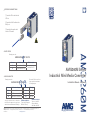
AMG AMG260M Series Installation guide

Type
Installation guide
www.amgsystems.com
AMG260M
amgsystems.com
D33680-00
AMG260M SeriesAMG260M Series
Industrial Mini Media ConverterIndustrial Mini Media Converter
Installation Manual - HardwareInstallation Manual - Hardware
INTERFACE CONNECTIONS
Insert the SFP module into the
SFP slot.
Insert the Cat5/6 cable into the
RJ45 port.
Insert the bre patch cable
into the SFP module.
PORT SPEEDS
Example part code:
AMG260M-1GAT-1S-P30
Character RJ45 Port Speed SFP* Port Speed
F10/100 Base-T(X) 100/1000 Base-FX
G10/100/1000 Base-T(X)
*SFP’s supplied separately. Refer to AMG website and SFP Datasheets for available models.
POE CAPABILITIES
Example part code:
AMG260M-1GBT-1S-P90
Characters PoE Standard Supported
None Non-PoE Model
AT IEEE 802.3at 30W Port
BT IEEE 802.3bt 60/90W Port
Characters PoE Budget
P30 30W Max
P90 90W Max
PD Class 1 PD
Check the product label to determine
the PoE power supported on each port
and the units total maximum PoE budget.
IEEE 802.3at Models
Type 1 & 2 PoE support
Mode A PSE only
IEEE 802.3bt Models
Type 1, 2, 3 & 4 PoE
support. Mode A
and/or Mode B PSE
Ensure the PSU size used is at
least equal to the maximum
PoE budget gure.
AMG Systems Ltd. 4 Pioneer Way, Castleford, WF10 5QU, UK T: +44 (0) 1767 600 777 E: technical@amgsystems.com
AMG Systems Inc. 62 Spring Hill Road, Trumbull, CT 06611, USA T: +1-855-AMGPOE1 (855-264-7631)
DIN RAIL MOUNT INSTALLATION
SURFACE MOUNT INSTALLATION
Attach the supplied DIN
rail clip using 2x M3×6mm
screws included in the box.
Multiple mounting options
are available:
Rear Mount
Base Mount
Side Mount
Attach the supplied wall
bracket using 2x M3×4mm
screws included in the box.
Multiple mounting options
are available:
Rear Mount
Base Mount
Side Mount
DIP SWITCH 4 - 250M EXTENDED DISTANCE
1GAT-1S
P30
AMG260M
4
G-24
S
4
X
S
A
MG
5
10
1GAT-1S
P30
AMG260M
4
G-24
S
4
X
S
A
MG
5
10
Switching DIP switch 4 to the ON
position will enable the 250m (820 ft)
Extended Distance feature.
The Extended Distance feature allows for a maximum
distance of 250m (820 ft) on the RJ45 copper port.
In this mode the speed is limited to 10Mb and also relies
on the connected device being able to support and
negotiate correctly with the AMG260M at 10Mb.
It is recommeded to test this feature before deployment
as it may not be suitable for some cameras etc.
Care should be taken when attempting to also extend
PoE over long distances. The maximum distance
possible will be determined by the PSU voltage to the
AMG260M.
Contact AMG Technical Services for further support.
Max
250m
1 6
Optional magnetic mounting kit is available separately. Order part code: AMGMNT-MAG-02
1GBT-1S
P90
AMG260M
4G
-24
S
4
X
S
A
MG
5
10
X
X
POWER
LED INDICATORS
Warning
Do not exceed the rated voltage
Observe correct voltage polarity
Model Type Voltage
Non-PoE Models 12-56 VDC
30W PoE Models 48-56 VDC
90W PoE Models 52-56 VDC
Model Type Power
DC Models 2.5W Max*
PD Model 802.3af
Class 1
*Excludes PoE Load
+
-
Power
Input
LED Colour Description
PWR Blue DC input present
ALRM Red Alarm condition triggered
SFP
LINK/ACT
O No SFP link connection
Green SFP link present (ashes with
data trac activity)
RJ45
LINK/ACT
O No Ethernet link connection
Green Ethernet link present (ashes
with data trac activity)
RJ45
POE
O No PoE being supplied
Yellow PoE is being delivered
RJ45
PD
O No PoE input detected
Yellow PoE input is active
DIP SWITCH 3 - LINK FAULT PASS-THROUGH
1GBT-1S
P90
AMG260M
4G
-24
S
4
X
S
A
MG
5
10
1GBT-1S
P90
AMG260M
4G
-24
S
4
X
S
A
MG
5
10
X
Switching DIP switch 3 to the ON
position will enable the Link Fault Pass-
Through feature.
The feature is activated when a link down event is
detected on the RJ45 port of the AMG260M unit.
This could be caused by an edge device fault such as a
camera going oine, a copper cable fault or a power
issue to the edge device.
When activated the Alarm LED on the AMG260M unit
will ash red.
When activated the AMG260M device will manually
force the SFP port into a link down state.
This will allow the fault condition to be propogated back
to the head end equipment which can then be monitored
and alarms generated etc.
The SFP port will remain in a link down state until the
AMG260M detects that the RJ45 port returns to a link
up state.
2 5
EARTH PROTECTION
To provide correct protection from ESD
and Surge events ensure that the unit
is correctly earthed using the provided
earth connection point in accordance
with local electrical codes & standards.
(cable not provided)
DIP SWITCHES
Switch Description
1 Reserved
2 Remote Device Reset
3 Link Fault Pass-Through
4 250M Extended Distance
Remove DIP switch cover
to access 4 DIP switches.
DIP SWITCH 2 - REMOTE DEVICE RESET
1GBT-1S
P90
AMG260M
4G
-24
S
4
X
S
A
MG
5
10
1GBT-1S
P90
AMG260M
4G
-24
S
4
X
S
A
MG
5
10
X
1GBT-1S
P90
AMG260M
4
G-24S
4
X
S
A
M
G
510
X
Switching DIP switch 2 to the ON
position will enable the Remote Device
Reset feature.
The feature is activated by causing the SFP port to go
into a link down state.
This can be achieved by either disconnecting the
ber cable at the head end location or by forcing the
head end ber port into a link down state (if directly
connected to a managed switch).
When activated the Alarm LED on the AMG260M unit
will ash red.
When activated the AMG260M device will perform
a complete reset. This will reset the internal Ethernet
switch IC and also will reset any connected device that is
powered by PoE from the AMG260M unit as shown.
A single reset will be performed.
If a further reset is required then the above step should
be repeated to cause a further link down event on the
SFP ber port.
3 4
  • Page 1 1
  • Page 2 2
  • Page 3 3
  • Page 4 4

AMG AMG260M Series Installation guide

Type
Installation guide

Ask a question and I''ll find the answer in the document

Finding information in a document is now easier with AI