
DIESEL GENERATOR
MMG 150 • MMG 170 • MMG 235
OPERATING MANUAL

2
INTRODUCTION
This manual provides information and procedures to safely operate and maintain the engine and generator. For your
own safety and protection from physical injury, carefully read, understand, and observe the safety instructions
described in this manual. The information contained in this manual was based on machines in production at the time
of publication. Magnum Products LLC reserves the right to change any portion of this information without notice.
DO NOT MODIFY or use this equipment for any application other than which it was designed for.
Magnum Products LLC recommends that a trained and licensed professional perform all electrical wiring and testing
functions. Any wiring should be in compliance with the United States National Electric Code (NEC), state and local
codes and Occupational Safety and Health Association (OSHA) guidelines.
Keep a copy of this manual with the unit at all times. Additional copies are available from Magnum Products LLC, or
can be found at www.m-p-llc.com. An engine operator’s manual was also supplied with the unit at the time of
shipment from the factory. The manual provides detailed operation and maintenance procedures for the engine.
Additional copies of the engine operators manual are available from the engine manufacturer.
MAGNUM PRODUCTS LLC
215 Power Drive • Berlin, WI 54923
U.S.A.
Phone: 920-361-4442
FAX: 920-361-4416
Toll Free: 1-800-926-9768
www.m-p-llc.com
For technical or parts QUESTIONS, please contact Magnum Products’ Customer Support or
Technical Support team at 920-361-4442. Please have your serial number available.
To ORDER SERVICE PARTS, please contact the dealer from which you purchased the unit,
or call Magnum Products to locate a dealer in your area.
Supplemental information may be available for your unit; when ordering parts ALWAYS
check for a supplement that applies to your unit. A supplement may have been provided with
your unit and can be found on the Magnum Products LLC website.
Engine Make: __________________________________________
Engine Serial Number: ___________________________________
Engine Model Number: ___________________________________
Generator Make:________________________________________
Generator Model Number: ________________________________
Generator Serial Number:_________________________________
Unit Model Number: _____________________________________
Unit Serial Number:______________________________________
WARNING
CALIFORNIA PROPOSITION 65 WARNING:
Diesel engine exhaust and some of its constituents are known to the state of California
to cause cancer, birth defects and other reproductive harm.

3
TABLE OF CONTENTS
Page
INTRODUCTION ................................................................................................................................... 2
TABLE OF CONTENTS ......................................................................................................................... 3
SAFETY NOTES ....................................................................................................................................4
OPERATING SAFETY ........................................................................................................................... 4
ENGINE SAFETY .................................................................................................................................. 5
ELECTRICAL SAFETY .......................................................................................................................... 5
TOWING SAFETY ................................................................................................................................. 6
REPORTING TRAILER SAFETY DEFECTS ......................................................................................... 6
UNIT SERIAL NUMBER LOCATIONS .................................................................................................. 7
SAFETY SYMBOL SUMMARY .............................................................................................................. 8
SPECIFICATIONS ................................................................................................................................. 9
UNIT DIMENSIONS ............................................................................................................................. 12
SERVICE LOCATIONS ....................................................................................................................... 13
MAIN CONTROL PANEL FEATURES, STANDARD ........................................................................... 14
MAIN CONTROL PANEL FEATURES, WITH OPTIONAL CAM LOCKS ............................................ 16
DIGITAL CONTROLLER FEATURES AND FUNCTIONS ................................................................... 18
MAGNUM DIGITAL CONTROLLER (MDC) ......................................................................................... 18
GENERATOR MONITORING .............................................................................................................. 19
ENGINE MONITORING .......................................................................................................................20
FINE VOLTAGE ADJUSTMENT .........................................................................................................21
GENERATOR START UP ....................................................................................................................22
PRE- START CHECK LIST ..................................................................................................................22
MANUAL STARTING OF THE GENERATOR ..................................................................................... 22
“AUTO” (REMOTE) STARTING OF THE GENERATOR .................................................................... 24
SHUTTING DOWN THE GENERATOR .............................................................................................. 24
MAGNUM DIGITAL CONTROLLER INFORMATION DISPLAYS, FUNCTIONS AND RESET ...........25
MAGNUM DIGITAL CONTROLLER (MDC) – GENERATOR OPERATIONAL STATUS .................... 25
MAGNUM DIGITAL CONTROLLER (MDC) - ALARM MANAGEMENT ..............................................25
MAGNUM DIGITAL CONTROLLER (MDC)- LIST OF POSSIBLE ALARMS/DESCRIPTIONS .......... 26
JOHN DEERE ECU INFORMATION DISPLAYS AND FUNCTIONS .................................................. 27
MAGNUM DIGITAL CONTROLLER (MDC) – HISTORY .................................................................... 28
ADJUSTING THE DISPLAY BACK LIGHTING .................................................................................. 28
RESETTING OF THE “TIME TO SERVICE” REMINDER ................................................................... 29
TROUBLESHOOTING AUTOMATIC SHUTDOWN CONDITIONS ..................................................... 29
GENERATOR OUTPUT CONNECTION LUGS ................................................................................... 31
GENERATOR CAM LOCK CONNECTIONS (OPTIONAL) .................................................................. 32
VOLTAGE SELECTOR SWITCH (MMG 150 & MMG 170 ONLY) ...................................................... 33
4-POSITION VOLTAGE SELECTOR SWITCH (OPTIONAL) ............................................................. 34
CHANGING OUTPUT VOLTAGE (MMG 235 ONLY) ......................................................................... 35
EMERGENCY STOP SWITCH ............................................................................................................36
MAIN CIRCUIT BREAKER ..................................................................................................................36
VOLTAGE REGULATION ....................................................................................................................36
CUSTOMER CONVENIENCE OUTLETS ...........................................................................................37
DERATING FOR ALTITUDE ................................................................................................................ 37
REMOTE START TERMINAL BLOCK ................................................................................................. 37
TRANSFER SWITCH .......................................................................................................................... 38
ENGINE AND GENERATOR MAINTENANCE .................................................................................... 39
DAILY WALK AROUND INSPECTION ................................................................................................ 39
BELT TENSION ................................................................................................................................... 39
ENGINE BREAK-IN REQUIREMENTS ............................................................................................... 40
DAILY MAINTENANCE CHECKS ........................................................................................................ 40
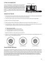
LIFTING THE GENERATOR ...............................................................................................................41
TOWING THE TRAILER ...................................................................................................................... 41
TRAILER WHEEL BEARINGS ............................................................................................................ 41
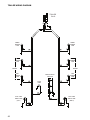
TRAILER WIRING DIAGRAM .............................................................................................................. 42
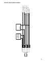
ELECTRIC BRAKE WIRING HARNESS ............................................................................................. 43
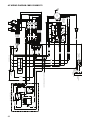
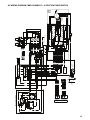
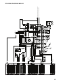
AC WIRING DIAGRAM: MMG150-MMG170 ....................................................................................... 44
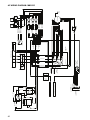
AC WIRING DIAGRAM: MMG150-MMG170 - 4-POSITION PHASE SWITCH ................................... 45
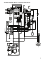
AC WIRING DIAGRAM: MMG235 .......................................................................................................46
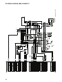
AC WIRING DIAGRAM: MMG235 - 4-POSITION PHASE SWITCH ................................................... 47
DC WIRING DIAGRAM: MMG150-MMG170 ....................................................................................... 48
DC WIRING DIAGRAM: MMG235 .......................................................................................................49
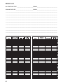
SERVICE LOG ..................................................................................................................................... 50
NOTES ................................................................................................................................................. 51

4
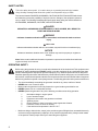
This is the safety alert symbol. It is used to alert you to potential personal injury hazards.
Obey all safety messages that follow this symbol to avoid possible injury or death.
SAFETY NOTES
This manual contains DANGERS, WARNINGS, CAUTIONS, NOTICES and NOTES which must
be followed to prevent the possibility of improper service, damage to the equipment, personal
injury or death. The following formatting options will apply when calling the readers attention to
the DANGERS, WARNINGS, CAUTIONS, NOTICES and NOTES.
DANGER
INDICATES A HAZARDOUS SITUATION WHICH, IF NOT AVOIDED, WILL RESULT IN
DEATH OR SERIOUS INJURY.
WARNING
Indicates a hazardous situation which, if not avoided, could result in death or serious
injury.
CAUTION
Indicates a hazardous situation which, if not avoided, may result in minor or moderate injury.
NOTICE
Indicates a hazardous situation which, if not avoided, may result in property or equipment
damage.
Note: Notes contain additional information important to a procedure and will be found within the
regular text body of this manual.
OPERATING SAFETY
Before using the generator be sure you read and understand all of the instructions! This equipment was
designed for specific applications; DO NOT modify or use this equipment for any application other than
which it was designed for. Equipment operated improperly or by untrained personnel can be dangerous!
Read the operating instructions and familiarize yourself with the location and proper use of all instruments
and controls. Inexperienced operators should receive instruction from someone familiar with the equipment
before being allowed to operate or set up the generator. The following points should be practiced at all times:
• The area immediately surrounding the generator should be dry, clean, and free of debris.
• NEVER start a unit in need of repair.
• Make certain the generator is securely fastened to a good earthen ground before use.
• NEVER operate unit on a combustible surface.
• NEVER operate the generator if any of the following conditions exist during operation:
1. Noticeable change in engine speed.
2. Loss of electrical output.
3. Equipment connected to the generator overheats.
4. Sparking occurs.
5. Engine misfires or there is excessive engine/generator vibration.
6. Protective covers are loose or missing.
7. If the ambient air temperature is above 110° F.
• Make sure slings, chains, hooks, ramps, jacks, and other types of lifting devices are attached securely
and have enough weight-bearing capacity to lift or hold the equipment safely. Always remain aware
of the position of other people around you when lifting the equipment.

5
ENGINE SAFETY
Internal combustion engines present special hazards during operation and fueling! Failure to follow the
safety guidelines described below could result in severe injury or death. Read and follow all safety warnings
described in the engine operator's manual. A copy of this manual was supplied with unit when it was
shipped from the factory.
• DO NOT run engine indoors or in an area with poor ventilation unless exhaust hoses are used. Diesel
engine exhaust contains carbon monoxide, a deadly, odorless and colorless gas which, if inhaled, can
cause nausea, fainting or death. Make sure engine exhaust cannot seep into closed rooms or ventilation
equipment.
• DO NOT fill fuel tank near an open flame, while smoking, or while engine is running. DO NOT fill tank
in an enclosed area with poor ventilation.
• DO NOT operate with the fuel tank cap loose or missing.
• DO NOT touch or lean against hot exhaust pipes or engine cylinders.
• DO NOT clean air filter with gasoline or other types of low flash point solvents.
• DO NOT remove engine coolant cap while engine is hot.
• DO NOT operate the unit without a functional exhaust system. Prolonged exposure to sound levels in
excess of 85 DBA can cause permanent hearing loss. Wear hearing protection when working around
a running engine.
• Keep hands, feet and loose clothing away from moving parts on the generator and engine.
• Keep area around exhaust pipes and air ducts free of debris to reduce the chance of an accidental fire.
• Batteries contain sulfuric acid which can cause severe injury or death. Sulfuric acid can cause eye
damage, burn flesh or eat holes in clothing. Protective eye wear and clothing are necessary when
working on or around the battery. Always disconnect the NEGATIVE (-) battery cable from the
corresponding terminal before performing any service on the engine or other components.
ELECTRICAL SAFETY
The unit is powered by a generator driven by a diesel engine. While the engine is running, potentially lethal
voltages are present at all the outlets located on the control panel, and at the connection lugs and cam
lock receptacles. Failure to follow the safety guidelines described below could result in severe injury or
death.
• Only a qualified and licensed electrician should make connections to the generator.
• NEVER wash the unit with any high pressure hoses or power washers.
• NEVER start the unit under load. The circuit breakers must be in the “OFF” position when starting the
unit in MANUAL mode. The circuit breakers can be in the “ON” position only when started in the AUTO
mode. A transfer switch must be used in the AUTO mode to deflect the load upon start up.
• ALWAYS disconnect the NEGATIVE (-) battery cable from the corresponding terminal before perform-
ing any service on the engine, generator or any other components. Remove the NEGATIVE (-) battery
cable from the corresponding terminal if the unit is to be stored or transported.
• ALWAYS use extreme caution when servicing this unit in damp conditions. Do not service the unit if
your skin or clothing is wet. Do not allow water to collect around the base of the unit.
• ALWAYS connect the unit to a good earthen ground before use. Follow any local, state or United
States National Electric Code (NEC) guidelines.

6
Towing a trailer requires care! Both the trailer and vehicle must be in good condition and securely fastened
to each other to reduce the possibility of an accident. Also, some states require that large trailers be
registered and licensed. Contact your local Department of Transportation office to check on license
requirements for your particular unit.
• Check that the hitch and coupling on the towing vehicle are rated equal to, or greater than, the trailer's
“gross vehicle weight rating” (GVWR).
• Check tires on trailer for tread wear, inflation, and condition.
• Inspect the hitch and coupling for wear or damage. NEVER tow trailer using defective parts!
• Make sure the trailer hitch and the coupling are compatible. Make sure the coupling is securely fastened
to the vehicle.
• Connect safety chains in a crossing pattern under the tongue and attach the breakaway cable TO THE
REAR BUMPER OF THE TOWING VEHICLE. Do not attach the cable to the trailer hitch.
• Make sure directional and brake lights on the trailer are connected and working properly.
• Check that lug nuts holding wheels are tight and that none are missing.
• Maximum recommended speed for highway towing is 45 mph. Recommended off-road towing speed
is not to exceed 10 mph or less depending on terrain.
Before towing the trailer, check that the weight of the trailer is equal across all tires. On trailers with
adjustable height hitches, adjust the angle of the trailer tongue to keep the trailer as level as possible. On
units equipped with a tandem axle trailer, a large angle between the trailer and tow vehicle will cause more
weight to be carried by one axle, which could cause premature wear on the tires and axles and cause
potentially unsafe operating conditions.
The trailer is equipped with hydraulic surge brakes or electric surge brakes. Check the operation of the
brakes by braking the vehicle at a slow speed before entering traffic. Both the trailer and the vehicle should
brake smoothly. If the trailer seems to be pushing, check the level in the surge brake fluid reservoir. When
towing, maintain extra space between vehicles and avoid soft shoulders, curbs and sudden lane changes.
If you have not pulled a trailer before, practice turning, stopping, and backing up in an area away from
heavy traffic.
A film of grease on the coupler will extend coupler life and eliminate squeaking. Wipe the coupler clean
and apply fresh grease each time the trailer is towed.
TOWING SAFETY
REPORTING TRAILER SAFETY DEFECTS
If you believe your trailer has a defect which could cause a crash or could cause injury or death, you should immediately
inform the National Highway Traffic Safety Administration (NHTSA) in addition to notifying Magnum Products LLC.
If NHTSA receives similar complaints, it may open an investigation; and if it finds that a safety defect exists in a group
of vehicles, it may order a recall and remedy campaign. However, NHTSA cannot become involved in individual
problem between you, your dealer, or Magnum Products LLC.
To contact NHTSA, you may either call the Auto Safety Hotline toll-free at 1-888-327-4236 (TTY:1-800-424-9153),
go to http://www.safercar.gov; or write to:
Administrator
NHTSA
1200 New Jersey Avenue S.E.
Washington, DC 20590
You can also obtain other information about motor vehicle safety from http://www.safercar.gov.

7
MAGNUM PRODUCTS LLC
BERLIN, WI 54923 USA
(800) 926-9768
MODEL
SERIAL NUMBER
000000
kg lbs
MADE IN USA
Trailer ID Tag
MANUFACTURED BY/FABRIQUE PAR: MAGNUM PRODUCTS LLC
GVWR/PNBV:
DATE:
COLD INFL. PRESS./PRESS.
DE GONF A FROID
GAWR/PNBE TIRE/PNEU RIM/JANTE
KPA(PSI/LPC)
SGL/DUAL
THIS VEHICLE CONFORMS TO ALL APPLICABLE STANDARDS PRESCRIBED UNDER THE
CANADIAN MOTOR VEHICLE SAFETY REGULATIONS IN EFFECT ON THE DATE OF
MANUFACTURE. / CE VEHICULE EST CONFORME A TOUTES LES NORMES QUI LUI
SONT APPLICABLES EN VERTU DU REGLEMENT SUR LA SECURITE DES VEHICULES
AUTOMOBILES DU CANADA EN VIGUEUR A LA DATE SA FABRICATION.
V.I.N./N.I.V.: 00000000000000000
TYPE/TYPE DE VEHICULE: TRAILER
THIS VEHICLE CONFORMS TO ALL
APPLICABLE U.S. FEDERAL MOTOR
VEHICLE SAFETY STANDARDS
(FMVSS) IN EFFECT ON THE DATE
OF MANUFACTURE SHOWN ABOVE.
V.I.N. Tag
UNIT ID Tag
Serial Number
kg
lbs
rpm hz amb. temp.
V
A
Model
RATING: CONT. STAND BY
3 Phase
1 Phase
KVA
LR 114630-1
FOR ELECTRICAL
EQUIPMENT ONLY.
POUR MATERIAL
ELECTRIQUE SEULEMENT.
MADE IN USA
PRODUCTS LLC
215 Power Drive
Berlin, WI 54923
1-800-926-9768
TM
Mfg. Code
V
A
KW
®
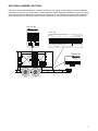
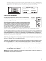
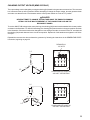
UNIT SERIAL NUMBER LOCATIONS
Refer to the locations illustrated below to find the unit ID tag, V.I.N. tag and trailer ID tag on your unit. Important
information, such as the unit serial number, model number and Vehicle Identification Number (V.I.N.) for your trailer
are found on these tags. Record the information from these tags, so it is available if the tags are lost or damaged.
When ordering parts or requesting technical service information, you may be asked to specify this information.

8
Hot surface(s) nearby.
Fire/explosion hazard; Keep
open flames away from unit.
Read and understand the
supplied operator’s manual
before operating unit.
Remove negative battery
cable before performing
any service on unit.
Stop engine before making
connections.
Use clean diesel fuel only.
Unit electrical ground.
Hearing protection required
while operating unit with doors
open.
Anchor/tie down point.
Lift here only.
Asphyxiation hazard; Operate
in well ventilated area.
Dangerous voltage may be
present.
Never change switch position
while engine is running.
Burn/scald hazard;
pressurized steam.
Fan hazard; Keep body parts
clear of this area.
Isolate generator to prevent
electrocution hazard.
Belt/entanglement hazard; Keep
body parts clear of this area.
Safety alert symbol; Used to
alert you to potential personal
injury hazards.
Stop engine before fueling.
Engine running.
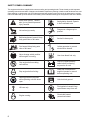
SAFETY SYMBOL SUMMARY
This equipment has been supplied with numerous safety and operating decals. These decals provide important
operating instructions and warn of dangers and hazards. Replace any missing or hard-to-read decals and use care
when washing or cleaning the unit. Decal placement and part numbers can be found in the parts section or parts
manual included with your unit. Below is a summary of the intended meanings for the symbols used on the decals.

9
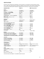
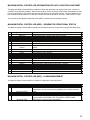
SPECIFICATIONS
Read this manual carefully before attempting to use this generator. The potential for property damage, personal
injury or death exists if this equipment is misused or installed incorrectly. Read all of the manuals included with this
unit. Each manual details specific information regarding items such as set up, use and service requirements.
MAGNUM MODEL MMG 150 MMG 150 Super Start
Engine
Make/Brand..............................................................John Deere................................... John Deere
Model .......................................................................PE6068HF285.............................. PE6068HF285
Horsepower - prime hp (kW) ..................................180 (134)...................................... 180 (134)
Horsepower - standby hp (kW) ...............................197 (147)...................................... 197 (147)
Operating Speed rpm .............................................1800 ............................................. 1800
Displacement in
3
(L) ...............................................415 (6.8)....................................... 415 (6.8)
Cylinders - qty ..........................................................6 ................................................... 6
Fuel Consumption - 100% prime gph (Lph) ...........9.8 (37.1)...................................... 9.8 (37.1)
Battery Type .............................................................Group 31 ...................................... Group 31
Battery Voltage (Quantity per Unit) ..........................12V (1) ......................................... 12V (1)
Battery Rating ..........................................................1000 CCA..................................... 1000 CCA
Generator
Make/Brand..............................................................Marathon Electric ......................... Marathon Electric
Model .......................................................................363PSL1661 ................................ 432PSL6210
Type, Insulation........................................................Brushless, H................................. Brushless, H
Generator Set (Engine/Generator)
3Ø - Standby kW (kVA) ...........................................127 (159)...................................... 131 (164)
Amps - 3Ø Standby 480V (208V) A ........................191 (441)...................................... 197 (455)
3Ø - Prime kW (kVA) ..............................................116 (145) ...................................... 119 (149)
Amps - 3Ø Prime 480V (208V) A ............................174 (402)...................................... 179 (414)
1Ø - Standby kW (kVA) ...........................................114 (114) ...................................... 128 (128)
Amps - 1Ø Standby - 240V A ..................................475 ............................................... 533
1Ø - Prime kW (kVA) ..............................................106 (106)...................................... 117 (117)
Amps - 1Ø Prime - 240V A .....................................442 ............................................... 488
Frequency Hz ..........................................................60 ................................................. 60
Power Factor............................................................1 (1Ø), 0.8 (3Ø)............................ 1 (1Ø), 0.8 (3Ø)
Weights
Dry Weight, Skid Mounted lbs (kg) .........................5944 (2696).................................. 6409 (2907)
Operating Weight, Skid Mounted lbs (kg) ..............8500 (3856).................................. 8965 (4066)
Dry Weight, Trailer Mounted* lbs (kg) ....................7340 (3329).................................. 7805 (3540)
Operating Weight, Trailer Mounted* lbs (kg) ..........9896 (4489).................................. 10361 (4700)
*Standard trailer only. Consult factory for custom trailer weights.
Capacities
Fuel Tank Volume gal (L) ........................................342 (1295).................................... 342 (1295)
Usable Fuel Volume gal (L) ....................................313 (1185) .................................... 313 (1185)
Coolant (incl. engine) qt (L) ....................................42.0 (39.7).................................... 42.0 (39.7)
Oil (incl. filter) qt (L) ................................................31.5 (29.8).................................... 31.5 (29.8)
Maximum Run Time hrs .........................................32 ................................................. 32
AC Distribution
Circuit Breaker Size .................................................600 ............................................... 600
Voltage Selection .....................................................3 Position Switch (lockable) ......... 3 Position Switch (lockable)
Voltage Regulation ...................................................+/- 1%........................................... +/-1%
Voltages Available 1Ø ..............................................120, 139, 208, 220, 240, 277 ....... 120, 139, 208, 220, 240, 277
Voltages Available 3Ø ..............................................208, 220, 440, 480 ....................... 208, 220, 440, 480
Trailer
Number of Axles ......................................................2 ................................................... 2
Capacity - Axle Rating lbs (kg) ...............................6000 (2722).................................. 6000 (2722)
Tire Size in ..............................................................16 ................................................. 16
Brakes......................................................................Surge............................................ Surge
Hitch - Standard .......................................................3" Ring ......................................... 3" Ring
Maximum Tire Pressure psi ....................................75 ................................................. 75
SPECIFICATIONS ARE SUBJECT TO CHANGE WITHOUT NOTICE.

10
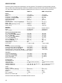
SPECIFICATIONS
Read this manual carefully before attempting to use this generator. The potential for property damage, personal
injury or death exists if this equipment is misused or installed incorrectly. Read all of the manuals included with this
unit. Each manual details specific information regarding items such as set up, use and service requirements.
MAGNUM MODEL MMG 170 MMG 170 Super Start
Engine
Make/Brand..............................................................John Deere................................... John Deere
Model .......................................................................PE6068HF285.............................. PE6068HF285
Horsepower - prime hp (kW) ..................................216 (161)...................................... 216 (161)
Horsepower - standby hp (kW) ...............................237 (177)...................................... 237 (177)
Operating Speed rpm .............................................1800 ............................................. 1800
Displacement in
3
(L) ...............................................415 (6.8)....................................... 415 (6.8)
Cylinders - qty ..........................................................6 ................................................... 6
Fuel Consumption - 100% prime gph (Lph) ...........10.9 (41.3).................................... 10.9 (41.3)
Battery Type .............................................................Group 31 ...................................... Group 31
Battery Voltage (Quantity per Unit) ..........................12V (1) ......................................... 12V (1)
Battery Rating ..........................................................1000 CCA..................................... 1000 CCA
Generator
Make/Brand..............................................................Marathon Electric ......................... Marathon Electric
Model .......................................................................431PSL6306 ................................ 432PSL6210
Type, Insulation........................................................Brushless, H................................. Brushless, H
Generator Set (Engine/Generator)
3Ø - Standby kW (kVA) ...........................................150 (188)...................................... 158 (198)
Amps - 3Ø Standby 480V (208V) A ........................226 (522)...................................... 238 (550)
3Ø - Prime kW (kVA) ..............................................137 (171)...................................... 144 (180)
Amps - 3Ø Prime 480V (208V) A ............................206 (475)...................................... 217 (500)
1Ø - Standby kW (kVA) ...........................................125 (125)...................................... 154 (154)
Amps - 1Ø Standby - 240V A ..................................521 ............................................... 642
1Ø - Prime kW (kVA) ..............................................120 (120)...................................... 142 (142)
Amps - 1Ø Prime - 240V A .....................................500 ............................................... 592
Frequency Hz ..........................................................60 ................................................. 60
Power Factor............................................................1 (1Ø), 0.8 (3Ø)............................ 1 (1Ø), 0.8 (3Ø)
Weights
Dry Weight, Skid Mounted lbs (kg) .........................6139 (2785).................................. 6604 (2996)
Operating Weight, Skid Mounted lbs (kg) ..............8567 (3886).................................. 9032 (4097)
Dry Weight, Trailer Mounted* lbs (kg) ....................7535 (3418).................................. 8000 (3629)
Operating Weight, Trailer Mounted* lbs (kg) ..........9963 (4519).................................. 10428 (4730)
*Standard trailer only. Consult factory for custom trailer weights.
Capacities
Fuel Tank Volume gal (L) ........................................342 (1295).................................... 342 (1295)
Usable Fuel Volume gal (L) ....................................313 (1185) .................................... 313 (1185)
Coolant (incl. engine) qt (L) ....................................31.5 (29.8).................................... 31.5 (29.8)
Oil (incl. filter) qt (L) ................................................33.0 (31.2).................................... 33.0 (31.2)
Maximum Run Time hrs .........................................29 ................................................. 29
AC Distribution
Circuit Breaker Size .................................................700 ............................................... 700
Voltage Selection .....................................................3 Position Switch (lockable) ......... 3 Position Switch (lockable)
Voltage Regulation ...................................................+/- 1%........................................... +/-1%
Voltages Available 1Ø ..............................................120, 139, 208, 220, 240, 277 ....... 120, 139, 208, 220, 240, 277
Voltages Available 3Ø ..............................................208, 220, 440, 480 ....................... 208, 220, 440, 480
Trailer
Number of Axles ......................................................2 ................................................... 2
Capacity - Axle Rating lbs (kg) ...............................6000 (2722).................................. 6000 (2722)
Tire Size in ..............................................................16 ................................................. 16
Brakes......................................................................Surge............................................ Surge
Hitch - Standard .......................................................3" Ring ......................................... 3" Ring
Maximum Tire Pressure psi ....................................75 ................................................. 75
SPECIFICATIONS ARE SUBJECT TO CHANGE WITHOUT NOTICE.

11
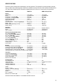
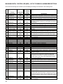
SPECIFICATIONS
Read this manual carefully before attempting to use this generator. The potential for property damage, personal
injury or death exists if this equipment is misused or installed incorrectly. Read all of the manuals included with this
unit. Each manual details specific information regarding items such as set up, use and service requirements.
MAGNUM MODEL MMG 235 MMG 235 Super Start
Engine
Make/Brand..............................................................John Deere................................... John Deere
Model .......................................................................PE6068HF485.............................. PE6068HF485
Horsepower - prime hp (kW) ..................................286 (213)...................................... 286 (213)
Horsepower - standby hp (kW) ...............................315 (235)...................................... 315 (235)
Operating Speed rpm .............................................1800 ............................................. 1800
Displacement in
3
(L) ...............................................415 (6.8)....................................... 415 (6.8)
Cylinders - qty ..........................................................6 ................................................... 6
Fuel Consumption - 100% prime gph (Lph) ...........15.2 (57.5).................................... 15.2 (57.5)
Battery Type .............................................................Group 31 ...................................... Group 31
Battery Voltage (Quantity per Unit) ..........................12V (1) ......................................... 12V (1)
Battery Rating ..........................................................1000 CCA..................................... 1000 CCA
Generator
Make/Brand..............................................................Marathon Electric ......................... Marathon Electric
Model .......................................................................431PSL6336 ................................ 433PSL6216
Type, Insulation........................................................Brushless, H................................. Brushless, H
Generator Set (Engine/Generator)
3Ø - Standby kW (kVA) ...........................................204 (255)...................................... 209 (261)
Amps - 3Ø Standby 480V (208V) A ........................307 (708)...................................... 251 (724)
3Ø - Prime kW (kVA) ..............................................186 (233)...................................... 190 (237)
Amps - 3Ø Prime 480V (208V) A ............................280 (647)...................................... 285 (658)
1Ø - Standby kW (kVA) ...........................................N/A ............................................... N/A
Amps - 1Ø Standby - 240V A ..................................N/A ............................................... N/A
1Ø - Prime kW (kVA) ..............................................N/A ............................................... N/A
Amps - 1Ø Prime - 240V A .....................................N/A ............................................... N/A
Frequency Hz ..........................................................60 ................................................. 60
Power Factor............................................................0.8 (3Ø) ........................................ 0.8 (3Ø)
Weights
Dry Weight, Skid Mounted lbs (kg) .........................6510 (2953).................................. 7330 (3325)
Operating Weight, Skid Mounted lbs (kg) ..............9100 (4128).................................. 9920 (4500)
Dry Weight, Trailer Mounted* lbs (kg) ....................8450 (3833).................................. 9270 (4205)
Operating Weight, Trailer Mounted* lbs (kg) ..........11040 (5008) ................................ 11860 (5380)
*Standard trailer only. Consult factory for custom trailer weights.
Capacities
Fuel Tank Volume gal (L) ........................................342 (1295).................................... 342 (1295)
Usable Fuel Volume gal (L) ....................................313 (1185) .................................... 313 (1185)
Coolant (incl. engine) qt (L) ....................................38.0 (35.9).................................... 38.0 (35.9)
Oil (incl. filter) qt (L) ................................................33.0 (31.2).................................... 33.0 (31.2)
Maximum Run Time hrs .........................................21 ................................................. 21
AC Distribution
Circuit Breaker Size .................................................800 ............................................... 800
Voltage Selection .....................................................Link/Reconnect Board.................. Link/Reconnect Board
Voltage Regulation ...................................................+/- 1%........................................... +/-1%
Voltages Available 1Ø ..............................................N/A ............................................... N/A
Voltages Available 3Ø ..............................................208, 480 ....................................... 208, 480
Trailer
Number of Axles ......................................................2 ................................................... 2
Capacity - Axle Rating lbs (kg) ...............................7000 (3175).................................. 7000 (3175)
Tire Size in ..............................................................16 ................................................. 16
Brakes......................................................................Surge............................................ Surge
Hitch - Standard .......................................................3" Ring ......................................... 3" Ring
Maximum Tire Pressure psi ....................................80 ................................................. 80
SPECIFICATIONS ARE SUBJECT TO CHANGE WITHOUT NOTICE.

12
50”
132”
77”
86”
210”
93”
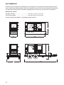
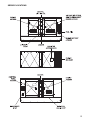
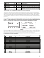
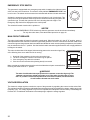
UNIT DIMENSIONS
Read this manual carefully before attempting to use this generator. The potential for property damage, personal
injury or death exists if this equipment is misused or installed incorrectly. Read all of the manuals included with this
unit. Each manual details specific information regarding items such as set up, use and service requirements.
Dimensions (L x W x H)
Skid Mounted in (m) ...............................................132 x 50 x 77 (3.35 x 1.27 x 1.96)
Trailer Mounted in (m) ............................................210 x 86 x 93 (5.33 x 2.18 x 2.36)
SPECIFICATIONS ARE SUBJECT TO CHANGE WITHOUT NOTICE.

13
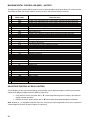
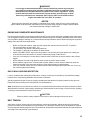
SERVICE LOCATIONS

14
12
3
4
7
891011
12
13
15
14
5
6
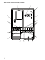
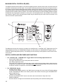
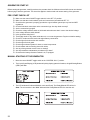
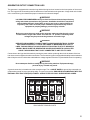
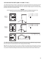
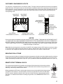
MAIN CONTROL PANEL FEATURES, STANDARD

15
1. DOCUMENT HOLDER
2. AIR FILTER METER: This gauge shows the condition of the air filter when the engine is running.
3. MAGNUM DIGITAL CONTROLLER (MDC): See pages 18-19 for additional information.
4. AUXILIARY LIGHT SWITCHES: These switches operate the optional control panel and interior lights.
5. CIRCUIT BREAKERS FOR 120V GFCI CONVENIENCE OUTLETS, 20A (2)
6. CIRCUIT BREAKERS FOR 120/240V CONVENIENCE OUTLETS, 50A (3)
7. 120/240V TWIST-LOCK CONVENIENCE OUTLETS (3): These outlets are used for connecting additional loads
or equipment to the generator.
8. CONNECTION FOR BATTERY CHARGER (OPTIONAL): Allows for 120VAC input to power onboard battery
charger.
9. CONNECTION FOR ENGINE BLOCK HEATER (OPTIONAL): Allows for 120VAC input to power the engine
block heater.
10. 120V GFCI DUPLEX CONVENIENCE OUTLETS: Outlets for additional equipment that may require Ground
Fault Interrupt (GFCI) protection.
11. REMOTE START TERMINAL BLOCK: Used to connect the generator to a dry-contact closure switch for remote
starting of the generator.
12. OUTPUT GROUND CONNECTION: Ground lug for attaching the generator to a good earthen ground.
13. CONNECTION TERMINAL LUGS: External loads are wired to these lugs.
14. DOOR SAFETY SWITCHES: The connection lug door is equipped with safety interlock switches that will trip
the main circuit breaker and disable the voltage regulator if the door is opened while the unit is operating.
15. MAIN CIRCUIT BREAKER FOR CONNECTION LUGS: The MMG 150 has one 600A breaker, the MMG 170
a 700A breaker and the MMG 235 has an 800A breaker.

16
12
3
5
8
910
11
12
13
14
16
15
17
18
6
7
ENGINEENGINE
STARTSTART
ENGINEENGINE
STOPSTOP
MANUAL AUTO
ALARM
CANCEL
FAULT
RESET
ALARM/FAULT
READY/MANUAL READY/AUTO
WARNING
RUNNING SUPPLYING LOAD
OPERATION
PAGE
SELECT
ENTER
DIAGNOSTICS
STATUS
CONTROLCONTROL
ONON
CONTROLCONTROL
OFFOFF
MAN
AUT
Ready
PF 0.00
RPM 0
0 kW 0
4
15
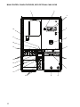
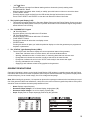
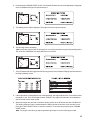
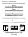
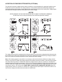
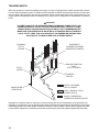
MAIN CONTROL PANEL FEATURES, WITH OPTIONAL CAM LOCKS

17
1. DOCUMENT HOLDER
2. AIR FILTER METER: This gauge shows the condition of the air filter when the engine is running.
3. MAGNUM DIGITAL CONTROLLER (MDC): See pages 18-19 for additional information.
4. AUXILIARY LIGHT SWITCHES: Operate optional control panel and interior lights.
5. CIRCUIT BREAKER FOR CAM LOCK CONNECTORS (OPTIONAL): Units equipped with one set of cam lock
receptacles (as shown) have one 450A breaker. Units equipped with two sets of cam lock receptacles have two
450A breakers.
6. CAM LOCK CONNECTORS (OPTIONAL): Series 16 Taper Nose 400A, 600V cam locks are connected here.
See page 32 for more information.
7. OUTPUT GROUND CONNECTION: (Green) Cam lock ground connection for attaching the generator to a good
earthen ground.
8. CONNECTION FOR BATTERY CHARGER (OPTIONAL): Allows for 120VAC input to power onboard battery
charger.
9. CONNECTION FOR ENGINE BLOCK HEATER (OPTIONAL): Allows for 120VAC input to power the engine
block heater.
10. 120/240V TWIST-LOCK CONVENIENCE OUTLETS (3): These outlets are used for connecting additional loads
or equipment to the generator.
11. REMOTE START TERMINAL BLOCK: Used to connect the generator to a dry-contact closure switch for remote
starting of the generator.
12. 120V GFCI DUPLEX CONVENIENCE OUTLETS (2): Outlets for additional equipment that may require Ground
Fault Interrupt (GFCI) protection.
13. OUTPUT GROUND CONNECTION: Ground lug for attaching the generator to a good earthen ground.
14. CONNECTION TERMINAL LUGS: External loads are wired to these lugs.
15. DOOR SAFETY SWITCHES: The connection lug door and cam lock door are equipped with safety interlock
switches that will trip the main circuit breaker and disable the voltage regulator if the doors are opened while the
unit is operating.
16. CIRCUIT BREAKERS FOR 120/240V CONVENIENCE OUTLETS, 50A (3)
17. CIRCUIT BREAKERS FOR 120V GFCI CONVENIENCE OUTLETS, 20A (2)
18. MAIN CIRCUIT BREAKER FOR CONNECTION LUGS: The MMG 150 has one 600A breaker, the MMG 170
a 700A breaker and the MMG 235 has an 800A breaker.

18
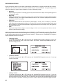
The MDC panel consists of five sections, including: the “CONTROL ON” / “CONTROL OFF” Toggle Switch and Fine
Voltage Adjustment Screw; the “OPERATION” keypad; the LCD window; the “DIAGNOSTICS” keypad; and the
“STATUS” Light Emitting Diodes (LED’s). The following is a brief summary of the operation of each section of the
control panel:
DIGITAL CONTROLLER FEATURES AND FUNCTIONS
1. The “CONTROL ON” / “CONTROL OFF” Toggle Switch and Fine Voltage Adjustment Screw
• Control On/Off Toggle Switch
This toggle switch powers-up the control panel and the controller.
• Fine Voltage Adjustment Screw
This screw may be adjusted to set the generator output voltage after the voltage selector switch has been
changed from one phase to another. This adjustment must
be accomplished within 45 seconds of start-up
so that the unit does not experience a shut down alarm for “SENSING”.
2. The “OPERATION” Keypad
• “ENGINE START” Button
The Power Screen Display must be in the “MAN” mode in the upper left corner of the LCD window display
and the “Ready/Manual” LED lit in the “Status” portion of the controller. Press the green “ENGINE START”
button to start the unit.
• “ENGINE STOP” Button
Press the red “ENGINE STOP” button to shut down the unit and start the “Stop Value” timer.
•“MANUAL W” Button
Press this button to change from the Automatic (Remote) starting mode to Manual starting mode.
MAGNUM DIGITAL CONTROLLER (MDC)
The Magnum Digital Controller (MDC) is an enhanced digital generator controller used to start, stop and monitor the
operation of the generator and the engine. The controller constantly monitors vital generator and engine functions
for a number of pre-programmed alarm and fault conditions. When a fault condition occurs, the engine will shut down
automatically and the Liquid Crystal Display (LCD) window will display the fault that caused the shutdown; to resume
operation the fault condition must be resolved. The controller has the ability to provide the display readout in English
and Spanish; other languages are available. A screen print out of the display screen is also available. This controller
also records a “History” of the unit’s performance which may be viewed at any time and will not be removed or lost
when the controller is powered down.

19
• “AUTO X” Button
Press this button to change from Manual starting mode to Automatic (remote) starting mode.
• “ALARM CANCEL” Button
When an alarm is activated, either visually or audibly, press this button to silence or cancel the alarm.
• “FAULT RESET” Button
Press this button to clear the fault from the LCD window after the fault has been corrected.
Press “FAULT RESET” and “ENTER” to clear the John Deere ECU Alarm List Codes.
3. The Liquid Crystal Display (LCD)
• This window will toggle between the Generator Display Screen and the Engine Display Screen upon start-
up of the unit. By viewing these screens, the operator will be able to monitor both the engine and generator
status while the unit is running.
4. The “DIAGNOSTICS” Keypad
•“S” Scroll-Up Button
Press this button to scroll-up within the LCD window.
•“T” Scroll-Down Button
Press this button to scroll-down within the LCD window.
• “PAGE SELECT” Button
Pressing this button will select the next display screen.
• “ENTER” Button
Pressing this button will place you inside the particular display to review the generators pre programmed
setpoints or parameters.
5. The “STATUS” Light Emitting Diodes (LED’s)
• These six LED’s will illuminate to display the current operational status of the generator;
- Alarm/Fault: Indicates active or inactive alarms, but not reset shutdown alarms.
- Warning: Indicates an active or inactive alarm, or a warning alarm that has not been reset.
- Ready/ Manual: Indicates the controller is ready to start and in the manual mode.
- Ready/Auto: Indicates the unit is in the “AUTO” mode ready for the remote start signal.
- Running: Indicates the unit is running.
- Supplying Load: Indicates a load is being applied to the generator.
GENERATOR MONITORING
Generator information is shown on the Liquid Crystal Display (LCD) window in a toggling manner with the Engine
information after the first 60 seconds of operation, then every five seconds thereafter. The generator display screen
will show frequency, line to neutral voltage, line to line voltage and amperage.
Note: When loading the generator, it is important to observe the amperage to determine the load balance on each
line of the generator. Minor load unbalances, usually 5% or less, will not cause any particular problems. Every effort
should be made to distribute the load equally between all lines.
• Hertz: Displays output frequency.
• Generator Output Voltage: Line to Neutral display, single phase (1Ø).
• Generator Output Voltage: Line to Line display, 3 phase (3Ø).
• Amps: Displays the AC output amperage produced by the generator.

20
ENGINE MONITORING
Engine information is shown on the Liquid Crystal Display (LCD) window in a toggling manner with the Generator
information after the first 60 seconds of operation and then every five seconds thereafter. The engine display screen
will show oil pressure, engine coolant temperature, fuel level and battery voltage.
• Oil Press:
Displays engine oil pressure. The display registers oil pressure between 0-100 psi. Normal operating pressure
is between 35-80 psi.
• Eng Temp:
Displays the temperature of the engine’s coolant. If the coolant temperature exceeds the Maximum Water
Temperature of 230° F the engine will automatically shut down. Zero “0” will be displayed until a minimum
temperature of 100° F is reached.
• Fuel Level:
Displays the relative fuel level in the fuel tank in percent (50% = 1/2 tank, 75% = 3/4 tank, etc.). If the fuel
level drops below a programmed low fuel point – usually at 15%, a low fuel warning and optional audio alarm
will be activated. If the fuel level drops below the programmed low fuel limit, usually at 5%, the engine will
automatically shut down.
• Vbat:
Displays the engine battery voltage. A normal reading is 13-14V on 12 volt systems and 24-26 on 24 volt
systems, (with the engine running).
Additional information may be viewed while the unit is in “MANUAL” or “AUTO” mode. By pressing the “Page Select”
button, the operator will select one of the following screens; “Running” screen, “Password” screen, or “History” screen.
In each of these page selections the operator may press the “S” or “T” buttons on the “DIAGNOSTICS” keypad to
display additional information as follows:
• “Running” screen:
The operator may press the “S” or “T” buttons on the “DIAGNOSTICS” keypad to display the “Alarm List”
screen, “ECU Alarm List” screen, “Run Hours” screen, “ECU Values” screen, Engine display screen and
Generator display screen.
• “Password” screen:
The operator may press the “S” or “T” buttons on the “DIAGNOSTICS” keypad to move the “>” cursor up
or down a list of text.
• “History” screen:
The operator may press the “S” or “T” buttons on the “DIAGNOSTICS” keypad to move the “>” cursor up
or down a list of the latest alarm or shutdown codes. Pressing the “Enter” button at a particular selection will
allow the operator to scroll to the right in the LCD window to view the generator operating parameters at the
time of the alarm or shutdown. The history of alarms or codes of the unit are saved in the digital controller.
Page is loading ...
Page is loading ...
Page is loading ...
Page is loading ...
Page is loading ...
Page is loading ...
Page is loading ...
Page is loading ...
Page is loading ...
Page is loading ...
Page is loading ...
Page is loading ...
Page is loading ...
Page is loading ...
Page is loading ...
Page is loading ...
Page is loading ...
Page is loading ...
Page is loading ...
Page is loading ...
Page is loading ...
Page is loading ...
Page is loading ...
Page is loading ...
Page is loading ...
Page is loading ...
Page is loading ...
Page is loading ...
Page is loading ...
Page is loading ...
Page is loading ...
Page is loading ...
-
 1
1
-
 2
2
-
 3
3
-
 4
4
-
 5
5
-
 6
6
-
 7
7
-
 8
8
-
 9
9
-
 10
10
-
 11
11
-
 12
12
-
 13
13
-
 14
14
-
 15
15
-
 16
16
-
 17
17
-
 18
18
-
 19
19
-
 20
20
-
 21
21
-
 22
22
-
 23
23
-
 24
24
-
 25
25
-
 26
26
-
 27
27
-
 28
28
-
 29
29
-
 30
30
-
 31
31
-
 32
32
-
 33
33
-
 34
34
-
 35
35
-
 36
36
-
 37
37
-
 38
38
-
 39
39
-
 40
40
-
 41
41
-
 42
42
-
 43
43
-
 44
44
-
 45
45
-
 46
46
-
 47
47
-
 48
48
-
 49
49
-
 50
50
-
 51
51
-
 52
52


Magnum MMG 170 Operating instructions
- Category
- Power generators
- Type
- Operating instructions
Ask a question and I''ll find the answer in the document
Finding information in a document is now easier with AI
Related papers
-
Magnum MMG 170 Operating instructions
-
Generac MMG35FHD Operating instructions
-
-
-
-
-
-
-
-
Other documents
-
-
-
-
-
-
-
-
-
Generac MMG35D Operating instructions
-