Bunn 1SH User manual
- Category
- Coffee making accessories
- Type
- User manual
This manual is also suitable for
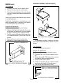
Bunn 1SH is a commercial-grade coffee server designed to keep coffee hot and fresh for extended periods. It boasts a powerful heating system that maintains the ideal temperature for coffee, ensuring your customers enjoy a consistently delicious brew. The server's user-friendly design features an easy-to-use control panel and clear markings for precise filling. Its durable construction and high-quality materials guarantee long-lasting performance in demanding commercial environments.
Bunn 1SH is a commercial-grade coffee server designed to keep coffee hot and fresh for extended periods. It boasts a powerful heating system that maintains the ideal temperature for coffee, ensuring your customers enjoy a consistently delicious brew. The server's user-friendly design features an easy-to-use control panel and clear markings for precise filling. Its durable construction and high-quality materials guarantee long-lasting performance in demanding commercial environments.


-
 1
1
-
 2
2
-
 3
3
-
 4
4
-
 5
5
-
 6
6
-
 7
7
-
 8
8
-
 9
9
-
 10
10


Bunn 1SH User manual
- Category
- Coffee making accessories
- Type
- User manual
- This manual is also suitable for
Bunn 1SH is a commercial-grade coffee server designed to keep coffee hot and fresh for extended periods. It boasts a powerful heating system that maintains the ideal temperature for coffee, ensuring your customers enjoy a consistently delicious brew. The server's user-friendly design features an easy-to-use control panel and clear markings for precise filling. Its durable construction and high-quality materials guarantee long-lasting performance in demanding commercial environments.
Ask a question and I''ll find the answer in the document
Finding information in a document is now easier with AI
Related papers
-
Bunn 2SH Soft Heat Stand, Stainless Steel User manual
-
Bunn Dual® GPR 120/208V User manual
-
Bunn G9T HD, Tall, Interface-Dual Owner's manual
-
Bunn FPG User manual
-
Bunn Titan® Dual DBC® 120/240V Brewer User manual
-
-
-
-
Bunn JDF-4 Operating instructions
-
Bunn Ultra-2 HP White/Stainless, Manual Fill, Extended Handle User manual
Other documents
-
Bunn-O-Matic 1SH Stand Datasheet
-
Bunn-O-Matic SINGLE SH User manual
-
Bunn-O-Matic BrewWISE User manual
-
-
-
Bunn-O-Matic TITAN SINGLE User manual
-
-
-
-