7 4
The Polarizer should be inserted into either of the Filter Receptacles on the Reflected Light
Illuminator.
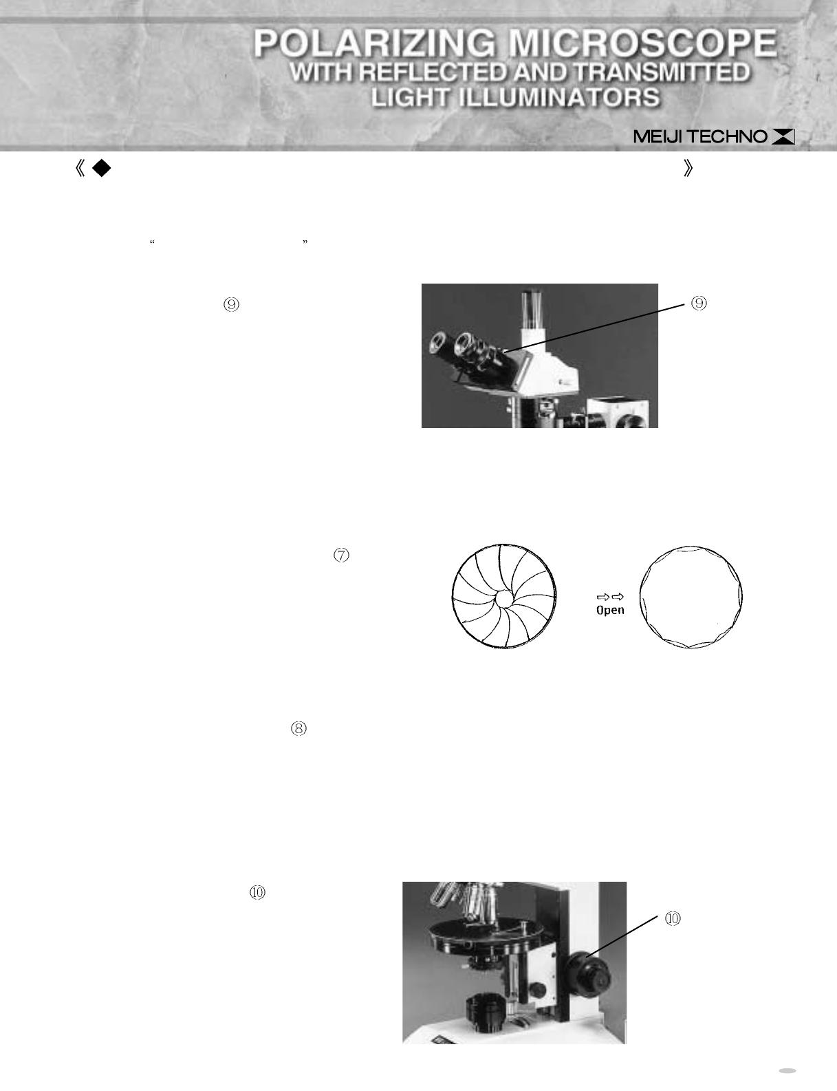
Slide in the Analayer
into the optical path.
The above two processes bring on a state of
CROSSING between Polarizer and
Analyser, making the field of view quite dark.
In case it does not become dark enough, move
the adjusting knob@1 of the Polarizer
to and
fro gently to find the fittest position.
BOTH TRANSMITTED AND REFLECTED ILLUMINATORS CAN BE USED SIMULTANEOUSLY FOR
THE OBSERVATION OF SEMI-TRANSPARENT MATERIALS.
ROTATING STAGE
A ball-bearing circular stage, precisely rotatable through a full 360 degrees, is supplied as standard.
With rotation angular measurements can be made, reading by a vernier to 0.1 degrees.
CENTERING OF OBJECTIVES
When the microscope is shipped to you the objectives are factory par-centered. Therefore, check and
make sure that the objectives have been precisely seated on the optical axis. If it is even lightly off axis
the centering is required with the Hexagon keys supplied in the following way:
(1) Focus down on your specimen through the 10X objective mounted in the non-centerable locked-up
opening, aside from the other floating centerable nosepiece holes, and memorize the point of the
specimen appearing just on the eyepiece cross-line center.
(2)Turn the nosepiece and bring the next higher power objective to the position, and focus on the
specimen if necessary, and see whether the pinpoint of the specimen you memorized before is located
just at the cross point of the mark.
(3)In case the memorized pinpoint is
seen away from the cross point, it
must be brought to the cross point by
the use of the provided two Centering
Screws, which can be inserted into
the key holes on the nosepiece ring
and turned to move the pinpoint to
the cross point.
After you have focused on the specimen proceed as follows:-
(1)Move the sliders on which the two binocular eyepiece tubes are mounted in and out until the
distance between them is exactly the same as the distance between the pupils of the observers eyes.
(This is the
interpupillary distance .)
(2)When this is done, note the dimension which is
displayed in the window
of the slider. Always
remember to set to this distance when using the
microscope. It will be different for different
observers, so they will have to check the best
setting for themselves.
(3)Now use the fine focus to get a sharp image in the right-side eyepiece using your right eye.
(4)Using the left eye, adjust the diopter adjustment collar on the eyepiece in the left-hand eyepiece
tube to get the sharpest possible image. Do not use fine focus.
(5)Now turn the field iris adjustment ring
until the
field iris is seen in the field of view.
(6)Raise or lower the substage condenser so as to
focus the field iris as sharply as possible in the plane
of your specimen. When this is done open out the
field iris until it is just outside the field of view.
(7)Removing one of the eyepieces, observe the disc of light coming from the back of the objective in
use. Close down the aperture iris
, using the lever on the substage condenser, until only about 70%-
80% of the disc of light observed remains visible. (Note that the microscope is now set up for use with
the 10X objective. Similar adjustments to those mentioned above should be made when using any of
the objectives required.)
(8)Regarding the note above, if you choose the 100X objective, immersion oil must be applied to the
specimen slide so that, when this objective is swung in and focused, both the specimen slide and the
100X objective are in good, bubble-free contact.
(9)The tension control knob
is provided to
allow the individual user to adjust the focus
tension to his/her own preference. Tension may
be increased by turning the knob with a
counterclockwise motion. A lighter tension may
be set by turning clockwise.
Window
Focused image of
closed field iris
Tension control
Adjusting knob @1
Polarizer
This picture shows the
Hexagon key inserted into
the key hole on the
nosepiece.
Analyzer


