Page is loading ...

Document 27-650 │ Edition ENG04 │ 2017-03-31
Manual
PCD1.P1001-J30
Power Quality Analyzer (PQA)

Saia-Burgess Controls AG
Manual PCD1.P1001-J30 │ Document 27-650 │ Version ENG 04 | 2017-03-31
PCD1.P1001-J30
Contents
0-1
0
0 Content
0.1 Document History .................................................................................. 0-5
0.2 Trademarks ........................................................................................... 0-5
1. Product description
2 Graphical Overview
3 Norms
4. Data logging
4.1 Cycling data logging .............................................................................. 4-2
4.1.1 Data structure ........................................................................................ 4-2
4.2 Events logging ....................................................................................... 4-3
4.2.1 Data structure ........................................................................................ 4-3
4.3 Data holding time .................................................................................. 4-3
5. Firmware update
5.1 Over the micro-USB port on the frontplate: ........................................... 5-1
5.2 Over the RS-485 interface: ................................................................... 5-1
6. Technical data
6.1 Accuracy ............................................................................................... 6-1
6.1.1 Voltage and current accuracy according to IEC61557-12 ..................... 6-1
6.1.2 Active power and energy accuracy according IEC61557-12 ................ 6-1
6.1.3 Reactive power and energy accuracy according IEC61557-12 ............ 6-1
6.1.4 Apparent power and energy accuracy according IEC61557-12 ............ 6-1
6.1.5 Harmonics and THD accuracy .............................................................. 6-2
6.1.6 Frequency and angles ........................................................................... 6-2
6.1.7 Power factor and cos Phi ..................................................................... 6-2
6.1.8 Temperature accuracy ........................................................................... 6-2
6.1.9 Refresh time .......................................................................................... 6-2
6.2 Energy measurement 4 quadrant .......................................................... 6-3
6.3 Events ................................................................................................... 6-4

Saia-Burgess Controls AG
Manual PCD1.P1001-J30 │ Document 27-650 │ Version ENG 04 | 2017-03-31
PCD1.P1001-J30
Contents
0-2
0
7. Menu structure
7.1 Home screen ......................................................................................... 7-1
7.2 Main menu ............................................................................................ 7-2
7.3 Measurements ...................................................................................... 7-2
7.3.1 Energy ................................................................................................... 7-2
7.3.2 Voltage .................................................................................................. 7-3
7.3.2.1 Voltage RMS ......................................................................................... 7-3
7.3.2.2 Voltage THD .......................................................................................... 7-4
7.3.2.3 SAG ....................................................................................................... 7-4
7.3.2.4 Low voltage ........................................................................................... 7-4
7.3.2.5 Voltage peak ......................................................................................... 7-5
7.3.2.6 SWELL .................................................................................................. 7-5
7.3.2.7 Over-voltage .......................................................................................... 7-5
7.3.2.8 Over-THD .............................................................................................. 7-6
7.3.3 Current .................................................................................................. 7-6
7.3.3.1 Current RMS ......................................................................................... 7-6
7.3.3.2 Current THD .......................................................................................... 7-7
7.3.3.3 Current TDD .......................................................................................... 7-7
7.3.3.4 Current peak ......................................................................................... 7-7
7.3.3.5 Over-current .......................................................................................... 7-8
7.3.3.6 Over-THD .............................................................................................. 7-8
7.3.3.7 Full load % ............................................................................................ 7-8
7.3.4 Power .................................................................................................... 7-9
7.3.4.1 Active power .......................................................................................... 7-9
7.3.4.2 Reactive power ..................................................................................... 7-9
7.3.4.3 Apparent power ..................................................................................... 7-9
7.3.4.4 Max power ............................................................................................. 7-10
7.3.4.5 Averaged power .................................................................................... 7-10
7.3.4.6 Reset Max ............................................................................................. 7-10
7.3.4.7 Reset Averaged ..................................................................................... 7-10
7.3.5 PF & Freq .............................................................................................. 7-11
7.3.6 Harmonics ............................................................................................. 7-11
7.3.7 Temperature .......................................................................................... 7-11
7.3.7.1 Temp meas ............................................................................................ 7-12
7.3.7.2 H/L temp ext. ......................................................................................... 7-12
7.3.7.3 H/L temp int. .......................................................................................... 7-12
7.3.7.4 Clear ext. temp ...................................................................................... 7-12
7.3.7.5 Clear int. temp ....................................................................................... 7-13
7.3.8 Clear events .......................................................................................... 7-13

Saia-Burgess Controls AG
Manual PCD1.P1001-J30 │ Document 27-650 │ Version ENG 04 | 2017-03-31
PCD1.P1001-J30
Contents
0-3
0
7.4 Measurement setup .............................................................................. 7-13
7.4.1 Nominal voltage .................................................................................... 7-13
7.4.2 Frequency ............................................................................................. 7-13
7.4.3 Current transformers ratio ..................................................................... 7-14
7.4.4 Wiring setup .......................................................................................... 7-14
7.4.5 Voltage thresholds ................................................................................. 7-14
7.4.6 Current thresholds ................................................................................. 7-15
7.4.7 Power averaging ................................................................................... 7-15
7.4.8 Recording setup .................................................................................... 7-15
7.4.9 Temperature settings ............................................................................. 7-15
7.4.9.1 External temperature ............................................................................. 7-16
7.4.9.2 Internal temperature .............................................................................. 7-16
7.5 System setup ........................................................................................ 7-16
7.5.1 Date & time ........................................................................................... 7-17
7.5.2 Serial setup ........................................................................................... 7-17
7.5.3 I/O setup ................................................................................................ 7-17
7.5.3.1 Digital input ........................................................................................... 7-18
7.5.3.2 Digital output ......................................................................................... 7-18
7.5.3.3 Relay 0 .................................................................................................. 7-18
7.5.3.4 Relay 1 .................................................................................................. 7-19
7.5.4 Backlight ................................................................................................ 7-19
7.5.5 Home cycle time .................................................................................... 7-19
7.5.6 Defaultcong ........................................................................................ 7-19
7.6 Storage .................................................................................................. 7-20
7.7 Info ........................................................................................................ 7-20
7.7.1 Product .................................................................................................. 7-20
7.7.2 File system ............................................................................................ 7-20
7.7.3 Date & time ........................................................................................... 7-21
7.7.4 Errors/Warnings .................................................................................... 7-21
7.7.5 Diagnosticle ........................................................................................ 7-21
8. LED behavior
8.1. LED function .......................................................................................... 8-1
8.1.1 Ph1-3 & N LED behavior ....................................................................... 8-2
8.1.1.1 Ph1-3: ................................................................................................... 8-2
8.1.1.2 N: ........................................................................................................... 8-2
9. Communication
9.1 USB Communication ............................................................................. 9-1
9.2 RS-485 Communication ........................................................................ 9-1
9.3 NFC Communication ............................................................................. 9-1
10. Mechanical dimensions
11. Installation
11.1 Connection technology .......................................................................... 11-1
11.2 Occupancy measuring inputs and power supply: .................................. 11-1
11.2.1 Power supply ......................................................................................... 11-2
11.2.2 Voltage measurement input .................................................................. 11-2
11.2.3 Current measurement input ................................................................. 11-2

Saia-Burgess Controls AG
Manual PCD1.P1001-J30 │ Document 27-650 │ Version ENG 04 | 2017-03-31
PCD1.P1001-J30
Contents
0-4
0
11.3 Occupancy digital part: ......................................................................... 11-3
11.3.1 Digital input .......................................................................................... 11-3
11.3.2 Digital output ......................................................................................... 11-4
11.3.3 Analog input for temperature measuring ............................................... 11-4
11.3.4 Relay contact ........................................................................................ 11-5
11.4 Installation ............................................................................................ 11-5
11.4.1 4 wire system, star-connection with neutral current measurement ....... 11-5
11.4.2 4-wire system, delta connection with neutral conductor ........................ 11-6
11.4.3 3-wire system delta connection ............................................................. 11-7
12.1 Conguringthemeasuringinputs ......................................................... 12-1
12.1.1 Averaging principle: ............................................................................... 12-3
12.2 ConguringtheI/O’s.............................................................................. 12-3
12.2.1 I/O functional description: ...................................................................... 12-6
12.2.1.1 Digital input ........................................................................................... 12-6
12.2.1.2 Digital output and relays contact .......................................................... 12-6
12.3 ConguringthresholdsforEvents ......................................................... 12-7
12.4 ConguretheLCD ................................................................................ 12-8
13. Commissioning of the PQA
13.1 Factory default settings ......................................................................... 13-1
14. FBoxes
15. Templates
A Annex
A.1 Icons ...................................................................................................... A-1
A.2 Communication registers SBus/Modbus ............................................... A-2
A.3 Flags for SBus/Modbus ......................................................................... A-8
A.4 FBoxes .................................................................................................. A-10
A.4.1 CongurationFBox ............................................................................... A-10
A.4.2 Measurement FBox ............................................................................... A-16
A.4.3 Status FBox ........................................................................................... A-18
A.4.4 Events FBox .......................................................................................... A-19
A.4.5 Harmonics FBox .................................................................................... A-26
A.5 Contact .................................................................................................. A-28

Saia-Burgess Controls AG
Manual PCD1.P1001-J30 │ Document 27-650 │ Version ENG 04 | 2017-03-31
PCD1.P1001-J30
Contents
0-5
0
0.1 Document History
Version Changes Published Comments
ENG01 2016-07-12 2016-07-12 - New document
ENG02 2016-08-16 2016-08-16 - Diverse feedbacks
ENG03 2016-08-30 2016-08-30 - Diverse feedbacks
ENG04 2017-01-19 2017-03-31 - Feedbacks from the development
0.2 Trademarks
Saia PCD
®
is a registered trademark of Saia-Burgess Controls AG.
Technical changes are subject to the state of technology.
Saia-Burgess Controls AG, 2017. © All rights reserved.
Published in Switzerland

Saia-Burgess Controls AG
Manual PCD1.P1001-J30 │ Document 27-650 │ Version ENG 04 | 2017-03-31
Product description
1-1
1
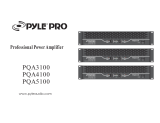
1. Product description
The PCD1.P1001-J30 Power Quality Analyzer (PQA) is a device for measuring
and checking the quality of the power system, manufactured as DIN rail equipment
in industrial quality. In addition to basic values such as current, voltage and power,
the power analyzer also has extensive analysis capabilities for detection of har-
monics, dips and swells, spikes, transients, etc.
The versatile measurement capabilities allow analysis of any disturbances with
cyclical/event-orienteddatarecordingandautomaticnoticationifameasured
quantity should be outside the tolerance limits.
In an installation without proper power quality electrical equipment, loads can be
disturbed, not work or they even can be destroyed. There are many types of poor
network quality and as many kinds of reasons for a poor power quality. A PQA
helps to avoid such situations. A measure that will help to extend the life cycle of a
machine.
The compact E-line design allows space-saving use in electrical cabinets.
The integrated RS-485 interface is available in S-Bus / Modbus and enables
communication with Saia PCD
®
controller or other master devices. The
engineering is through a comprehensive FBox Library with web templates very
ecientlyandquickly.
The main features are:
► Power analyzer with 0.5% accuracy
► Measure the 3 phases and neutral
► Current inputs for current transformer connection
► Peasurement data storage (Event / cyclic) to internal memory
► 1.9 inch LCD display
► Galvanically separated measuring inputs
► Temperature input
► Electrically isolated RS-485 interface for S-Bus / Modbus (switchable)
► 105 mm wide DIN rail devices (6 TE)
► Digital input/output
► Delays

NL
A
AI0UO0DO0DI0
D
S
/DA+DB-
L1 L2 L3 NI
N
I
3
I
2
I
1
NO1CO1NO0CO0
RL0 1
20%
50%
80%
110%
RT
DI
L1
L2
L3
N
DO
Pwr
Com
Err
PCD1.P1001-J30
Saia PCD1
48751kWh
P: 2016kW
PF total: 0.99
110%
Load:
Tot:
Saia-Burgess Controls AG
Manual PCD1.P1001-J30 │ Document 27-650 │ Version ENG 04 | 2017-03-31
PCD1.P1001-J30
Graphical overview
2-1
2
2 Graphical Overview
The graphical overview shows some of the main topics covered in the Operating
Manual of the PCD1.P1001-J30.
By clicking on the highlighted components and/or connections, you can jump
directly to the corresponding chapter in the document.
The numbers separated by dots indicate the relevant chapter numbers.
LCD
12.4
Current inputs
11.2.3
Relay contacts
11.3.4
Voltage inputs
11.2.2
Front LEDs
8.1
RS-485 interface
9.2
Power Supply
11.2.1
Digital/Analog I/O
11.3
Navigation keys
7
NFC
9.3
Micro USB port
9.1

Saia-Burgess Controls AG
Manual PCD1.P1001-J30 │ Document 27-650 │ Version ENG 04 | 2017-03-31
PCD1.P1001-J30
Norms
3-1
3
3 Norms
Product norm
EN 61557
Electrical safety in low voltage distribution systems up to 1000 V a.c. and 1500 V d.c.
– Equipment for testing, measuring or monitoring of protective measures –
Part 1: General requirements
Power supply 300 V CAT III, protection class II
Measurement inputs 120…240 V CAT II, protection class II
Part 12:
Performance measuring and monitoring devices
Class 0.5
Electromagnetic compatibility
EN 61000 Generic standards
Part 6-3: Emission standard for residential environments
EN55022 Conducted emission
EN55022 Radiated emission
Part 6-2: Immunity for Industrial environments
IEC 61000-4-4
Voltage burst main power circuit 2 kV, direct
Voltage burst on I/O ports 1 kV, capacitive
IEC 61000-4-5
Voltage Surge main power circuit 2 kV, 1.2/50 us
Voltage Surge on I/O ports 1 kV, 1.2/50 us
IEC 61000-4-2 ESD
8 kV Air
4 kV Contact
IEC 61000-4-6 Conducted radio frequency
0.15…80 MHz
10 Vrms
IEC 61000-4-3 RadiatedElectromagneticeld
80…2700 MHz
10 V/m

Saia-Burgess Controls AG
Manual PCD1.P1001-J30 │ Document 27-650 │ Version ENG 04 | 2017-03-31
Data logging
4-1
4
4. Data logging
Dataloggingisdoneintheinternalmemoryofthedevice.Therearetwodierent
set of logged values:
- cyclingloggingofpre-denedvalues
- event logging
Maximallesizeis2MB,whenthisvalueisreachedanewlewillbegenerated
with a new index.
TheCSVlesarestoredontheinternalashmemoryandcanbeaccessedwith
the following procedure:
● Go to menu point “Storage”
● Take menu “mass storage”
● Change to “yes”
● Press right key to activate the mass storage mode
● The LCD backlight is blinking, to signalize that the mass storage is activated
and the micro-USB port can be accessed with a normal PC like a memory stick.
The device is not measuring while it is in the mass storage mode
● To deactivate the mass storage mode, change the status on “yes”
● The device will reboot and is ready for measurement
Average: Used by the device to make calculations for the average power
Events: Eventloggingles(Eventslogging)
Measure: Dataloggingles(Cyclingdatalogging)
The device is not measuring while it is in the mass storage mode

Saia-Burgess Controls AG
Manual PCD1.P1001-J30 │ Document 27-650 │ Version ENG 04 | 2017-03-31
Cycling data logging
Data logging
4-2
4
4.1 Cycling data logging
Followingvalueswillbeloggedwithacycletimethatcanbedenedbytheuser:
● Active energy L1, L2 & L3
● Reactive energy L1, L2 & L3
● Active power L1, L2 & L3
● Reactive power L1, L2 & L3
● Max active power sum
● Max reactive power sum
● URMS 1, 2 & 3
● IRMS 1, 2, 3 & N
● Power factor 1, 2 & 3
● THD U1, U2 & U3
● THD I1, I2 & I3
● Frequency
● External temperature
● Active energy sum
● Reactive energy sum
● Apparent energy sum
Dataissavedincsvlesinafoldernamed“MEASURE”withaUnixtimestamp
and local date and time information.
4.1.1 Data structure
ExampleofleopenedinExcel.

Saia-Burgess Controls AG
Manual PCD1.P1001-J30 │ Document 27-650 │ Version ENG 04 | 2017-03-31
Events logging
Data logging
4-3
4
4.2 Events logging
Dataissavedincsvlesinafoldernamed“EVENTS”withaUnixtimestampand
local date and time information.
4.2.1 Data structure
ExampleofleopenedinExcel.
Events
Event ID Event Event ID Event
0 PQA_LOG_EVENT_SAG_U1 20 PQA_LOG_EVENT_THD_U3
1 PQA_LOG_EVENT_SAG_U2 21 PQA_LOG_EVENT_PEAK_I1_1
2 PQA_LOG_EVENT_SAG_U3 22 PQA_LOG_EVENT_PEAK_I1_2
3 PQA_LOG_EVENT_LOW_U1 23 PQA_LOG_EVENT_PEAK_I2_1
4 PQA_LOG_EVENT_LOW_U1 24 PQA_LOG_EVENT_PEAK_I2_2
5 PQA_LOG_EVENT_LOW_U3 25 PQA_LOG_EVENT_PEAK_I3_1
6 PQA_LOG_EVENT_PEAK_U1_1 26 PQA_LOG_EVENT_PEAK_I3_2
7 PQA_LOG_EVENT_PEAK_U1_2 27 PQA_LOG_EVENT_OVER_I1
8 PQA_LOG_EVENT_PEAK_U2_1 28 PQA_LOG_EVENT_OVER_I2
9 PQA_LOG_EVENT_PEAK_U2_2 29 PQA_LOG_EVENT_OVER_I3
10 PQA_LOG_EVENT_PEAK_U3_1 30 PQA_LOG_EVENT_OVER_IN
11 PQA_LOG_EVENT_PEAK_U3_2 31 PQA_LOG_EVENT_THD_I1
12 PQA_LOG_EVENT_SWELL_U1 32 PQA_LOG_EVENT_THD_I2
13 PQA_LOG_EVENT_SWELL_U2 33 PQA_LOG_EVENT_THD_I3
14 PQA_LOG_EVENT_SWELL_U3 34 PQA_LOG_EVENT_TEMP_EXT
15 PQA_LOG_EVENT_OVER_U1 35 PQA_LOG_EVENT_TEMP_INT
16 PQA_LOG_EVENT_OVER_U2 36 PQA_LOG_EVENT_PQA_START
17 PQA_LOG_EVENT_OVER_U3
18 PQA_LOG_EVENT_THD_U1
19 PQA_LOG_EVENT_THD_U2
4.3 Data holding time
Internal memory (1 GB) is big enough to log measurements for years even with a
1mincycliclogcongandeventshappeningeveryfewseconds.

Saia-Burgess Controls AG
Manual PCD1.P1001-J30 │ Document 27-650 │ Version ENG 04 | 2017-03-31
Firmware update
5-1
5
5. Firmware update
5.1 Over the micro-USB port on the frontplate:
0
9
0
9
R DI0
DB- /DA+ ⊥S
X1
X0
+DA
X3
X2
⊥D
DI1 DI2 DI3
DB- /DA+ ⊥S
Port0 Port1
+DA +DA -DA -DA -DA
Saia PCD1
DI0 1 2 3
IPw Com Err
Pwr
Com
Err
DALI
PCD1.F2611-C15
24V
+ + -
- -
NL
A
AI0UO0DO0DI0
D
S
/DA+DB-
L1 L2 L3 NI
N
I
3
I
2
I
1
NO1CO1NO0CO0
RL0 1
20%
50%
80%
110%
RT
DI
L1
L2
L3
N
DO
Pwr
Com
Err
PCD1.P1001-J30
Saia PCD1
48751kWh
P: 2016kW
PF total: 0.99
110%
Load:
Tot:
PG5
USB
Update direct via USB
The module is updated with Saia PG5
®
directly
via micro-USB.
5.2 Over the RS-485 interface:
Controller
PCD
PG5
NL
A
AI0UO0DO0DI0
D
S
/DA+DB-
L1 L2 L3 NI
N
I
3
I
2
I
1
NO1CO1NO0CO0
RL0 1
20%
50%
80%
110%
RT
DI
L1
L2
L3
N
DO
Pwr
Com
Err
PCD1.P1001-J30
Saia PCD1
48751kWh
P: 2016kW
PF total: 0.99
110%
Load:
Tot:
Update via a master controller (PCDx.Mxxxx)
The master controller connected to the PQA
module uses the RS-485 bus (S-Bus) to load the
rmwareupdateonthecorrespondingmodules.
Here the master controller is used as a gateway.
IfthePCD1.P1001-J30isconguredasModbusslave,Firmwareupdateisonlyavailablethrough
micro-USBport!ToloadanewFirmwareintothePQAweoerafree“FWDownloader”availableon
the sbc support page in the free “Service Online Tools for PG5”:
https://www.sbc-support.com/en/product-index/pg5-controls-suite/pg5-22-suite/
parts-of-pg5-22-suite/

Saia-Burgess Controls AG
Manual PCD1.P1001-J30 │ Document 27-650 │ Version ENG 04 | 2017-03-31
Meas specs
6
6-1
Accuracy
6. Technical data
6.1 Accuracy
6.1.1 Voltage and current accuracy according to IEC61557-12
Value Range Tolerance
Voltage 20%Vn≤V<Vmax ± 0.5%
Current 10%In≤V<Vmax ± 0.5%
6.1.2 Active power and energy accuracy according IEC61557-12
Current value Power factor Tolerance
1%In≤I<5%In 1 ± 1 %
5%In≤I<Imax 1 ± 0.5 %
2%In≤I10%In 0.5 inductive ± 1 %
0.8 capacitive ± 1 %
10%In≤I<Imax 0.5 inductive ± 0.6 %
0.8 capacitive ± 0.6 %
6.1.3 Reactive power and energy accuracy according IEC61557-12
Current value Sinus phi
Tolerance
2%In≤I<5%In 1 ± 1.25 %
5%In≤I<Imax 1 ± 1 %
2%In≤I10%In 0.5 inductive ± 1.25 %
10%In≤I<Imax 0.5 inductive ± 1 %
10%In≤I<Imax 0.25 ± 1.25 %
6.1.4 Apparent power and energy accuracy according IEC61557-12
Current value Tolerance
2%In≤I<5%In ± 1 %
5%In≤I<Imax ± 0.5 %

Saia-Burgess Controls AG
Manual PCD1.P1001-J30 │ Document 27-650 │ Version ENG 04 | 2017-03-31
Meas specs
6
6-2
Accuracy
6.1.5 Harmonics and THD accuracy
Value Tolerance
Voltage harmonics ± 5 %
Current harmonics ± 5 %
THD (0% - 20%) ± 0.6 %
TDD (0% - 100%) ± 0.6 %
6.1.6 Frequency and angles
Value Tolerance
Frequency ± 0.5 %
Phase angles ± 0.5 %
6.1.7 Power factor and cos Phi
Value Tolerance
Power factor ± 0.05 %
Phase angles ± 0.05 %
6.1.8 Temperature accuracy
Value Tolerance
Internal temperature ± 5 %
External temperature ± 1 °C –50°C≤…≤+400°C
6.1.9 Refresh time
Measure Max. refresh time
Voltage 330 ms
Current 330 ms
Power 330 ms
Energy 330 ms
Power factor 330 ms
CosPhi,Cosφ 330 ms
Frequency 330 ms
Phase angles 330 ms
THD/TDD 330 ms
Harmonics 6 s
Neutral current mismatch 12 s

Saia-Burgess Controls AG
Manual PCD1.P1001-J30 │ Document 27-650 │ Version ENG 04 | 2017-03-31
Meas specs
6
6-3
Energy measurement 4 quadrant
6.2 Energy measurement 4 quadrant
The PQA can measure in all 4 quadrants. To understand if the charge is capacitive
orinductivethefollowingdiagramshowstheenergydirections/ows.Thesignsof
thepowermeasurementsgivetheindicationinwhichquadranttheenergyows.
Reactive power, delivery
Active power, absorption
Negative active power (–)
Positive reactive power (+)
Negative cosine phi (–)
Positive active power (+)
Positive reactive power (+)
Positive cosine phi (+)
Active power
, delivery
Quadrant II Inductive
generator
Inductive
loads
Quadrant I
Quadrant III
Capacitive
generator
Capacitive
loads Quadrant IV
Negative active power (–)
Negative reactive power (–)
Negative cosine phi (–)
Positive active power (+)
Negative reactive power (–)
Positive cosine phi (+)
Reactive power, absorption
P
Q
S
φ
+P–P
+Q
–Q
0°±180°
+90°
–90°+270°
–270°

Saia-Burgess Controls AG
Manual PCD1.P1001-J30 │ Document 27-650 │ Version ENG 04 | 2017-03-31
Meas specs
6
6-4
Events
6.3 Events
The PCD1.P1001 device has a detection for the following events:
Bits in event register
A voltage sag (U.S.) or voltage dip (Brit-
ish) is a short duration reduction in RMS
voltage which can be caused by a short
circuit, overload or starting of electric
motors. A voltage sag happens when the
rms voltage decreases between 10 and
90 percent of nominal voltage for one-half
cycle to one minute.
0 SAG U1 event
1 SAG U2 event
2 SAG U3 event
100%
–100%
0%
Time
Voltage
90% Un
–10% Un
10% Un
–90% Un
Low Voltage
A Sag ends after one minute, after this
time it becomes a low voltage.
3 Low-voltage U1 event
4 Low-voltage U2 event
5 Low-voltage U3 event
0%
Time
90% Un
Un
1 min.
SAG start
SAG end
Low Voltage start
Low Voltage end
Voltage

Saia-Burgess Controls AG
Manual PCD1.P1001-J30 │ Document 27-650 │ Version ENG 04 | 2017-03-31
Meas specs
6
6-5
Events
Voltage Peak
A voltage peak is a extremely short over-
voltage like an ESD or Surge. Minimal de-
tection time of the PQA is 125 us (8 kHz)
If the RMS voltage reaches the peak
threshold level, peak events are ignored to
avoid continuous writes to the events log
le
6 Peak U1 event
7 Peak U2 event
8 Peak U3 event
100%
–100%
0%
Time
Voltage Peak
Voltage

Saia-Burgess Controls AG
Manual PCD1.P1001-J30 │ Document 27-650 │ Version ENG 04 | 2017-03-31
Meas specs
6
6-6
Events
SWELL Voltage
Avoltageswellsisdenedasarisein
rms voltage which is between 10 and 80
percent for a limited period between 0.5
cycles to 1 minute.
9 SWELL U1 event
10 SWELL U2 event
11 SWELL U3 event
100%
–100%
0%
Time
Voltage
Overvoltage
A Swell ends after one minute, after this
time it becomes an over voltage.
12 Over-voltage U1 event
13 Over-voltage U2 event
14 Over-voltage U3 event
0%
Time
110% Un
Un
1 min.
SWELL start
SWELL end
Over Voltage start
Over Voltage end
Voltage

Saia-Burgess Controls AG
Manual PCD1.P1001-J30 │ Document 27-650 │ Version ENG 04 | 2017-03-31
Meas specs
6
6-7
Events
Voltage THD
Voltage waveforms with a non-sinusoidal
shapecorrespondstothesumofdierent
sine-waveswithdierentmagnitudeand
phase, having frequencies that are multi-
ples of power-system frequency (harmon-
ics).
THD (Total Harmonic Distortion) is the
percent ratio of the sum of the powers of
all harmonic components to the power of
the fundamental frequency
15 Over-THD U1 event
16 Over-THD U2 event
17 Over-THD U3 event
100%
–100%
0%
Time
Voltage
100%
–100%
0%
Time
100%
–100%
0%
Time
Fundamental
pure sinuswave
plus
equals
× 3rd harmonic
Harmonically
distorted waveform
100%
–100%
0%
Time
Voltage
100%
–100%
0%
Time
100%
–100%
0%
Time
/