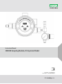
MSA SM5000 Sampling Module Owner's manual
- Type
- Owner's manual
MSA SM5000 Sampling Module
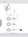
The MSA SM5000 Sampling Module is designed to sample gases or vapors in air. It is not capable of sampling the concentration of gases or vapors in steam or condensing streams or inert or oxygen deficient atmospheres.
The SM5000 Sampling Module - Aspirated Model is an essential tool for monitoring the presence of hazardous gases in various industrial and commercial settings. It is commonly used in conjunction with gas monitors to provide real-time readings of gas concentrations in the surrounding environment.
Some of the key features of the SM5000 Sampling Module - Aspirated Model include:
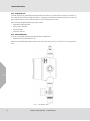
MSA SM5000 Sampling Module
The MSA SM5000 Sampling Module is designed to sample gases or vapors in air. It is not capable of sampling the concentration of gases or vapors in steam or condensing streams or inert or oxygen deficient atmospheres.
The SM5000 Sampling Module - Aspirated Model is an essential tool for monitoring the presence of hazardous gases in various industrial and commercial settings. It is commonly used in conjunction with gas monitors to provide real-time readings of gas concentrations in the surrounding environment.
Some of the key features of the SM5000 Sampling Module - Aspirated Model include:


-
 1
1
-
 2
2
-
 3
3
-
 4
4
-
 5
5
-
 6
6
-
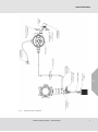 7
7
-
 8
8
-
 9
9
-
 10
10
-
 11
11
-
 12
12
-
 13
13
-
 14
14
-
 15
15
-
 16
16
-
 17
17
-
 18
18
-
 19
19
-
 20
20
-
 21
21
-
 22
22
-
 23
23
-
 24
24


MSA SM5000 Sampling Module Owner's manual
- Type
- Owner's manual
MSA SM5000 Sampling Module
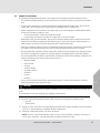
The MSA SM5000 Sampling Module is designed to sample gases or vapors in air. It is not capable of sampling the concentration of gases or vapors in steam or condensing streams or inert or oxygen deficient atmospheres.
The SM5000 Sampling Module - Aspirated Model is an essential tool for monitoring the presence of hazardous gases in various industrial and commercial settings. It is commonly used in conjunction with gas monitors to provide real-time readings of gas concentrations in the surrounding environment.
Some of the key features of the SM5000 Sampling Module - Aspirated Model include:
Ask a question and I''ll find the answer in the document
Finding information in a document is now easier with AI
Related papers
-
MSA SM5000 Sampling Module Owner's manual
-
-
-
-
-
-
-
-
-
Other documents
-
 BeamGrip FP Stryder™ Beam Anchor Owner's manual
-
Chord ULTIMA PRE 2 User manual
-
-
Chord ULTIMA PRE User manual
-
-
-
-
General Monitors S5000 Gas Monitor Operating instructions
-
-
Chord Ultima 5 User manual
