
Confidently. Accurately.
User Manual
GPS-Base
GNSS-aided inertial
navigation
system

Oxford Technical Solutions
2
Legal notices
Copyright of Oxford Technical Solutions at oxts.com.
© 2008–2018, Oxford Technical Solutions Ltd.
Unauthorised use, copying or distribution is not permitted. All brand names are trademarks of
their respective holders.
Any redistribution of the software must reproduce the above copyright notice, this list of
conditions and the following disclaimer in the documentation and/or other materials provided
with the distribution.
Environmental protection
Waste electrical products should not be disposed of with household waste. Please recycle
where facilities exist. Check with your Local Authority or OxTS representative for recycling
advice.

GPS-Base Manual
Revision: 180928
3
Disclaimer
Information furnished is believed to be accurate and reliable. However, Oxford Technical
Solutions Limited assumes no responsibility for the consequences of use of such information
nor for any infringement of patents or other rights of third parties which may result from its
use. No license is granted by implication or otherwise under any patent or patent rights of
Oxford Technical Solutions Limited. Specifications mentioned in this publication are subject
to change without notice and do not represent a commitment on the part of Oxford Technical
Solutions Limited. This publication supersedes and replaces all information previously
supplied. Oxford Technical Solutions Limited products are not authorised for use as critical
components in life support devices or systems without express written approval of Oxford
Technical Solutions Limited.
The software is provided by the copyright holders and contributors “as is” and any express or
implied warranties, including, but not limited to, the implied warranties of merchantability
and fitness for a particular purpose are disclaimed. In no event shall the copyright holders or
contributors be liable for any direct, indirect, incidental, special, exemplary, or consequential
damages (including, but not limited to, procurement of substitute goods or services; loss of
use, data, or profits; or business interruption) however caused and on any theory of liability,
whether in contract, strict liability, or tort (including negligence or otherwise) arising in any
way out of the use of this software, even if advised of the possibility of such damage.
The GPS-Base includes a radio modem specified at the time of manufacture, and needs to be
configured by the NAVbase software for the specific radio. The exact use of the radio differs
between regions and countries. The user of a GPS-Base must ensure the device is not
operated in any way without the permission of the local authorities on frequencies; other than
those specifically reserved and intended for use without a specific permit. OxTS or its
distributors are not responsible in any way for any claims or penalties arising from the
operation of its equipment with radio in ways contradictory to local regulations and/or
requirements and/or laws.
Contact details
Tel: +44 (0) 1869 814 253
Fax: +44 (0) 1869 251 764
Web: http://www.oxts.com
Email: [email protected]
Oxford Technical Solutions Limited
77 Heyford Park
Upper Heyford
Oxfordshire
OX25 5HD
United Kingdom
Revision
Document Revision: 180928.

Oxford Technical Solutions
4
Warranty
Oxford Technical Solutions Limited warrants its products to be free of defects in materials
and workmanship, subject to the conditions set forth below, for a period of one year from the
Date of Sale.
'Date of Sale' shall mean the date of the Oxford Technical Solutions Limited invoice issued
on delivery of the product. The responsibility of Oxford Technical Solutions Limited in
respect of this warranty is limited solely to product replacement or product repair at an
authorised location only. Determination of replacement or repair will be made by Oxford
Technical Solutions Limited personnel or by personnel expressly authorised by Oxford
Technical Solutions Limited for this purpose.
In no event will Oxford Technical Solutions Limited be liable for any indirect, incidental,
special or consequential damages whether through tort, contract or otherwise. This warranty
is expressly in lieu of all other warranties, expressed or implied, including without limitation
the implied warranties of merchantability or fitness for a particular purpose. The foregoing
states the entire liability of Oxford Technical Solutions Limited with respect to the products
herein.

GPS-Base Manual
Revision: 180928
5
Table of contents
Common abbreviations ..............................................................................................................7
Introduction ................................................................................................................................8
How do base stations work?...............................................................................................8
Transmitting the corrections.............................................................................................10
Correction types................................................................................................................11
Transmission frequency....................................................................................................11
File logging.......................................................................................................................12
Scope of delivery......................................................................................................................13
Conformance notices ...............................................................................................................15
Regulatory testing standards ............................................................................................15
Operation..................................................................................................................................16
Process of setting up the GPS-Base: ................................................................................16
General precautions ..........................................................................................................16
Selecting a suitable antenna location, and setting up the tripod......................................16
Setting up the tripod and antenna.....................................................................................17
Connecting the GNSS antenna and radio modem cables................................................18
Powering up and monitoring the GPS-Base ....................................................................19
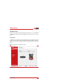
Communicating with the product ................................. ...........................................................22
The N AVbase interface............................................................................................................23
Product Selection..............................................................................................................23
Connection........................................................................................................................24
Remember port selection ..........................................................................................24
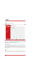
Settings..............................................................................................................................24
Averaging time..........................................................................................................25
Restore position from file .........................................................................................26
Enter antenna position...............................................................................................26
Leave unchanged ......................................................................................................26
Advanced...................................................................................................................26
Status .........................................................................................................................27
Communication.........................................................................................................28
Latitude, longitude, altitude......................................................................................28
Base Station ID .........................................................................................................28
Logging Novatel binary............................................................................................28
Logging RTCMv3.....................................................................................................29
Save position to file...................................................................................................29
Save position to GPS-Base .......................................................................................29
Save setting to GPS-Base .........................................................................................29
Start logging..............................................................................................................30
LED status................................................................................................................................31
Hardware LED descriptions ..............................................................................................20

Oxford Technical Solutions
6
SATEL radio status .......................................................................................................... 31
Freewave radio status ...................................................................................................... 31
Differential correction message format .................................................................................. 33
Message output and frequency:....................................................................................... 33
Repeatability............................................................................................................................ 35
Index ........................................................................................................................................38
Specifications...........................................................................................................................37

GPS-Base Manual
Revision: 180928
7
Common abbreviations
AB Dynamics Anthony Best Dynamics
CAN Controller Area Network
CEP Circular Error Probability
CPU Central Processing Unit
DGPS Differential Global Positioning System
ECCN Export Control Classification Number
EGNOS European Geostationary Navigation Overlay Service
FTP File Transfer Protocol
GAGAN GPS Aided Geo Augmented Navigation
GLONASS GLObal NAvigation Satellite System
GNSS Global Navigation Satellite System
GPS Global Positioning System
IMU Inertial Measurement Unit
INS Inertial Navigation System
LED Light Emitting Diode
MFDD Mean Fully Developed Deceleration
MSAS MTSAT Satellite Augmentation System
NMEA National Marine Electronics Association
NTRIP Networked Transport of RTCM via Internet Protocol
PPS Pulse(s) Per Second
RD
R
aw
D
ata (an OxTS file format)
RINEX Receiver INdependent EXchange format
RTK Real-Time Kinematics
SBAS Satellite Based Augmentation System
SDCM System for Differential Corrections and Monitoring
SPS Standard Positioning Service
TCP Transmission Control Protocol
TNC Threaded Neill-Concelman
TTFF Time To First Fix
TTL Transistor-Transistor Logic
UDP User Datagram Protocol
VUT Vehicle Under Test
WAAS Wide Area Augmentation System
WGS 84 World Geodetic System 1984
WLAN Wireless Local Area Network

Oxford Technical Solutions
8
How do base stations work?
A base station significantly increases the position accuracy of mobile GNSS receivers by
sending them corrections. The base station does this by independently identifying the errors
affecting the signal from each GNSS satellite it can see. Information about those errors is then
broadcast via radio modem or something similar. Other GNSS receivers in the area—which
are also connected to similar radio modems—receive the correction information and take it
into account when calculating their own position measurements. Removing the errors results
in more accurate position estimates.
A base station identifies the errors affecting GNSS signals in one of two ways. If the base
station is placed at a precisely surveyed location, it calculates a GNSS position measurement
in the normal way, then compares that calculated position to the known location. If the
position measurements match exactly, no correction is required. If there is a difference
however, the base station calculates the length of time each satellite signal would need to be
delayed by, in order to cause the difference between the surveyed location and the GNSS
measurement being produced.
Introduction
Thank you for choosing Oxford Technical Solutions.
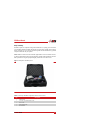
The GPS-Base is a highly-portable GPS base station that transmits differential corrections to
one or more differential enabled GNSS receivers via radio modem. The position accuracy of
differential and RTK GNSS receivers is improved when using the GPS-Base. The GPS-Base
is available with several different radio options. Different radios are required for license free
operation in different countries.
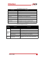
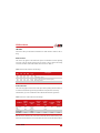
Four models of the GPS-Base exist, as listed in Table 1. All models are identical in their
operation but are able to track different satellite signals.
Table 1. GPS-Base models
Model
Measurement/Accuracy potential
a
a. Note: The maximum positioning accuracy is determined by the GNSS hardware in the mobile
receiver.
GPS-Base-2 L1/L2 GPS corrections suitable for positioning down to 1 cm accuracy
GPS-Base-2G L1/L2 GPS and L1/L2 GLONASS corrections suitable for positioning down to
1 cm accuracy

GPS-Base Manual
Revision: 180928
9
Alternatively, if the base station is not placed at an accurately surveyed location, the only way
for it to estimate the errors is to measure its own position as accurately as possible. It does this
by averaging the GNSS measurements over a period of time before settling on one location.
It then compares all further measurements to that chosen location in order to identify the
errors in the same way as before.
In both cases the base station calculates the errors affecting the signal from each satellite it
can see, and shares that information with other GNSS receivers in the local area. This is
normally achieved using radio modems or via an optional Wi-Fi system. A transmitter
connected to the base station broadcasts corrections, and each GNSS receiver has a modem
attached to it that listens for those corrections.
For RTK (Real-Time Kinematic) carrier-phase measurements, the principle is the same, but
the remote GNSS receiver also has to figure out the difference in the number of carrier-phase
cycles between the GPS-Base and itself. To do this, the GPS-Base measures the carrier-phase
of the signals from each satellite and transmits it to the remote system.
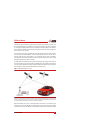
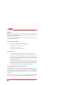
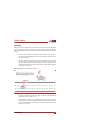
Figure 1.
Differential GNSS overview
The base station is either placed at a precisely known location or left to average its position over time. It can then
estimate the errors affecting each satellite it is tracking and broadcast information about those errors using radio
modems. Nearby GNSS receivers use radio modems to listen for corrections, and apply them to the signals from
the common satellites, reducing the errors in their own position calculations.
Differential GNSS can work in real-time applications because the errors affecting each
satellite vary slowly and predictably. The mobile GNSS receiver in the vehicle uses a model
to predict the error from each satellite. It can update its model when the radio link transmits

Oxford Technical Solutions
10
new data. It is not necessary for the mobile GNSS receiver to wait until the radio has
transmitted the correction before outputting its latest value. Depending on the GNSS receiver
in your INS, pseudo-range differential GNSS corrections can be up to 60 seconds old, and
RTK corrections can be up to 30 seconds old.
Transmitting the corrections
Each new GPS-Base is supplied with a pair of radio modems suitable for use in the country
specified when ordered. Typically, these radio modems have a range of 2–5 km line-of-sight.
However, trees, buildings, hills and other obstructions will limit the range that can be
achieved. Table 2 shows the different radios that can be supplied with the GPS-Base.
Please note that the use of the frequency bands 403–473 MHz is not harmonised across
Europe. Please contact OxTS if you require further details on the specific frequency band and
power settings for the radios supplied with your GPS-Base, and in which countries they can
be used.
While the GPS-Base will work seamlessly with our own GNSS-aided INS products, it is not
limited to them in any way. The GPS-Base can also serve as a general base station for other
products. To help achieve this, the GPS-Base transmits corrections inthree common formats:
•RTCA
•RTCA2
•RTCMv3
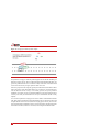
Table 2. Overview of different radios
Radio Specification
SATEL SATELLINE-EASy
(with display) 403–473 MHz
Up to 1 W, typically 5 km. License free bands available for many
European countries. Radio will typically cover eight bands with
25 kHz channel spacing, except for SATEL Easy radios, which have
a much wider range of configurable frequency
SATEL SATELLINE-EASy
(with display) 869 MHz
Up to 500 mW, typically 2 km. License free across most of European
Union. When using a radio in the 869 MHz band in countries or
regions where ETSI EN 300 220-1 is mandated, the option "Limit
output corrections message rate (ETSI EN 300 220-1)" must be
selected in NAVbase
FreeWave FGR2-900 MHz Up to 1 W, typically >10 km. License free in USA, Brazil, Canada

GPS-Base Manual
Revision: 180928
11
Correction types
The GPS-Base can transmit differential corrections in one of three different formats as shown
in Table 3. The output type should match one supported by the mobile receiver.
Transmission frequency
The rate at which each message type is broadcast is listed in the tables below. The limited
frequency is automatically selected when the Limit output corrections option is selected in
NAVbase.
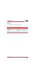
Table 3.
Differential correction formats supported by the
GPS-Base
Format Purpose
RTCA The RTCA format is suitable for GPS differential corrections but is not suitable for
GLONASS
RTCA2 The RTCA2 format is suitable for GPS and GLONASS differential corrections
RTCMv3 The RTCMv3 format is suitable for GPS and GLONASS differential corrections
Table 4.
RTCA message output
Message
Standard
frequency
Limited
frequency
a
a. Used when the Limit output corrections message rate (ETSI EN 300 220-1) option is enabled.
RTCAOBS (L1/L2 pseudo-range and carrier-phase) 1 Hz 0.25 Hz
RTCAREF (base station position) 0.2 Hz 0.2 Hz
RTCA1 (pseudo-range corrections) 1 Hz 0.25 Hz
Table 5.
RTCAv2 message output
Message
Standard
frequency
Limited
frequency
a
a. Used when the Limit output corrections message rate (ETSI EN 300 220-1) option is enabled.
RTCAOBS2 (L1/L2 GNSS+GLONASS pseudo-range
and carrier-phase)
1 Hz 0.25 Hz
RTCAREF (base station position) 0.2 Hz 0.1 Hz
RTCA1 (pseudo-range corrections) 1 Hz 1 Hz

Oxford Technical Solutions
12
File logging
As well as broadcasting differential corrections, the NAVbase software can log correction
data to the hard disk of the PC when connected. Files can be logged in Novatel binary and
RTCMv3 format.
Table 6.
RTCMv3 message output
Message
Standard update
rate
Limited update
rate
a
a. Used when the Limit output corrections message rate (ETSI EN 300 220-1) option is enabled.
RTCM1004 (extended L1/L2 GNSS pseudo-range and
carrier-phase)
1 Hz 0.25 Hz
RTCM1012 (extended L1/L2 GLONASS pseudo-range
and carrier-phase)
1 Hz 0.25 Hz
RTCM1005 (base station antenna position) 0.2 Hz 0.14 Hz
RTCM1007 (extended antenna descriptor and set-up
information). The base station firmware always configures
the base stati
on antenna as a Novatel GNSS Antenna
0.1 Hz 0.1 Hz
RTCM1033 (base station and antenna descriptor) 0.1 Hz 0.1 Hz

GPS-Base Manual
Revision: 180928
13
Scope of delivery
With the exception of a computer running Microsoft Windows, everything you need to utilise
your GPS-Base should be included with the delivery. Please check carefully that everything
shown on the delivery note is present. The following tables list the standard and any optional
components delivered with your product.
Please note:
the customer must check that the supplied radio can be used without a license,
or obtain a suitable license before using the GPS-Base. Oxford Technical Solutions cannot be
held responsible for using this equipment illegally without the correct radio license.
Figure 2.
Example of GPS-Base system
Table 7. Summary GPS-Base components common to all versions
Qty. Description
1 GPS-Base unit
1 15 m TNC-TNC GNSS antenna cable
1 Power cable
1 Radio modem cable
1 PC-USB cable

Oxford Technical Solutions
14
1 Transit case
1
Vexxis GNSS-802 antenna
1 Professional tripod
1 GPS-Base user manual
1 GPS-Base Quick Installation Guide
Table 8.
Additional components supplied with SATEL 380–420 MHz radios
Qty. Description
2 SATEL SATELLINE-EASy (with display) radio modem, 380–420 MHz
2 3 m Satel 420 magnetic antenna with TNC connector
Table 9. Additional components supplied with SATEL 869 MHz radios
Qty. Description
2 SATEL SATELLINE-EASy (with display) radio modem, 869 MHz
2 3 m Satel 869 magnetic antenna with TNC connector
Table 10. Additional components with Freewave radios
Qty. Description
2 Freewave FGR2-900 MHz radio modem
2 3 m Satel 869 magnetic antenna with TNC connector
2 Freewave FGR2-900 converter cable (short)
Table 7. Summary GPS-Base components common to all versions (Continued)
Qty. Description

GPS-Base Manual
Revision: 180928
15
Conformance notices
Any use or misuse of the GPS-Base, in a manner not intended by OxTS, may impair the
protection provided.
The GPS-Base complies with the radiated and conducted emission limits for CISPR 25 Level
2 and Class B of Part 15 of the FCC rules, and with the radiated emission and immunity limits
for Class B of EN 61326. These limits are designed to provide reasonable protection against
harmful interference in a residential installation.
This equipment generates, uses and can radiate radio frequency energy and, if not installed
and used in accordance with the instructions, may cause harmful interference to radio
communications. However, there is no guarantee that interference will not occur in a
particular installation. If this equipment does cause harmful interference to radio or television
reception, which can be determined by turning the equipment off and on, the user is
encouraged to try to correct the interference by one or more of the following measures:
• Re-orient or relocate the receiving antenna
• Increase the separation between the equipment and the receiver
The GPS-Base conforms to the requirements for CE.
Regulatory testing standards
• EN 55025
• CISPR 25 Level 2
• EN 61000-4-2
• EN 61000-4-3
• EN 55001 (EN 61326) Class B

Oxford Technical Solutions
16
Operation
The GPS-Base has been designed to be as easy to operate as possible. However, it is
important to have a sound understanding of how the system works, so please read the manual
thoroughly before operating the product.
The set-up procedure is summarised below. More detailed information on each step is also
presented in the following sections.
Process of setting up the GPS-Base:
1. Select a stable, suitable location for the GNSS antenna.
2. Connect all cables and then power up the system.
3. Configure the system, if required.
4. Download and convert the data if required.
General precautions
• The GPS-Base unit should not be left in the rain or other wet conditions.
• Ensure the antenna is not affected by gusts of wind—such as when vehicles pass.
• Never extend or shorten the GPS antenna cable. The loss in the cable is carefully
matched to the GPS-Base and lengthening or shortening the cable will reduce
the performance of the system.
• Never connect the GNSS antenna to the radio aerial connector, which uses the
same connector. The use of two TNC connectors is required since they have
much better ground properties compared to BNC connectors. The radio aerial
output has a high-power signal that may damage the GNSS antenna.
Selecting a suitable antenna location, and setting up the tripod
For the GPS-Base to work to specification, it is essential to put the antenna in a location
where it has a clear view of the sky. GNSS antennas do not only look for satellites from
above, they also receive signals from the side-down to an elevation of about 10° in all
directions. For that reason, it is important to place the antenna in the most open location
available to you.
One error that no base station can easily correct for are multi-path reflections from buildings
and trees. To avoid these, do not locate the antenna near trees and buildings, or other tall hard-

GPS-Base Manual
Revision: 180928
17
structures. It is also very important that the antenna does not move during the test. Ensure the
supplied tripod is stable enough not to move in the wind and that no one can bump into it.
When performing vehicle tests, consider gusts of wind that may be created by passing
vehicles.
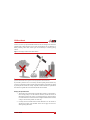
Figure 3.
Choosing a location for the GNSS antenna
Choose a location for the GNSS antenna that is not close to buildings or trees, as these can both affect GNSS
signals. The antenna needs to have a good view of the sky (not just above, but to the sides too).
If you intend to perform a test over several days, and will be packing the base-station away
overnight, it is important to mark the location of the GNSS antenna. It will need to be placed
in precisely the same location on each day. If possible, mount the antenna on a pole that has
been fixed in the ground and can be left behind until the test has finished.
Setting up the tripod and antenna
1. The tripod legs use a friction lock to maintain their position. To extend each leg,
twist each leg axially in an anti-clockwise direction (viewed from below) to
unlock the leg. Ensure each section is re-locked in position by axially twisting it
in a clockwise direction. It doesn't matter how high the GNSS antenna is located,
as long as it has the best possible view of the sky.
2. Carefully remove the GNSS antenna from the GPS-Base case. The antenna is
attached to the tripod via the threaded section. Do not apply excessive force
when tightening the antenna.

Oxford Technical Solutions
18
3. Ensure the tripod and antenna are located in a safe position and there is no
chance they can move or fall over.
Connecting the GNSS antenna and radio modem cables
Before powering up the GPS-Base, the GNSS antenna should be connected to the GNSS
connector using the supplied GNSS cable.
Figure 4.
GPS-Base cable connections
As shown above, the GNSS antenna connects to the left of the handle and the radio modem connects to the right.
Do not swap the connectors over or damage may occur.
If radio modems are being used to transmit and receive DGNSS corrections, one of the
supplied antennas should be connected to the Radio connector. The radio modem antenna
should be placed as high up as possible (to ensure good range is achieved), but should be
located at least 20 centimetres from the GNSS antenna.

GPS-Base Manual
Revision: 180928
19
Powering up and monitoring the GPS-Base
Please note that a number of factors affect the time taken for the GPS-Base to acquire
satellites. The process normally takes about 90 seconds, but can take up to 20 minutes if the
unit has been turned off for a long period of time or has been moved a significant distance
since last time it was used.
The first thing the GPS-Base loads as part of the boot process is a configuration file, which is
held in its internal memory. The configuration file controls how the GPS-Base behaves. The
first time an GPS-Base is powered up after delivery, the default settings are used. The default
settings tell the GPS-Base to average its position over a three-minute period (once it
computes a GNSS position) and to broadcast corrections in RTCMv3 format. The base
station ID will be set to OxTS.
Creating custom configurations using our NAVbase software is covered in the next section.

Power LED Description
LED Label LED State Description
PWR
Green solid Operational mode
Yellow solid In process of booting
Red solid
Error, for example, invalid receiver AUTH code
Firmware/Web UI update in progress
GNSS LED Description
LED Label LED State Description
GNSS
(indicates the position
status of the receiver)
Green solid PPP Solution
Green slow blink RTK integer ambiguity
Green fast blink Single point or SBAS position
Yellow solid No solution
Yellow blink
User Accuracy Level (UAL) out of bounds
(STEADYLINE)
If PwrPak7 configured as Base
Green solid Fixed position
Yellow solid Pending fixed position
Yellow blink Invalid fix
Hardware LED descriptions
INS LED
Description
LED Label LED State Description
(INS indicates the INS
status of the receiver
(PwrPak7-E1 or
PwrPak7 using an
external IMU only)
Off INS inactive
Green solid INS solution good
Green slow blink INS alignment complete
Green fast blink INS solution free
Green/Yellow alternating blink High variance
Yellow solid INS aligning/determining orientation
Red solid Error
Oxford Technical Solutions
20
Page is loading ...
Page is loading ...
Page is loading ...
Page is loading ...
Page is loading ...
Page is loading ...
Page is loading ...
Page is loading ...
Page is loading ...
Page is loading ...
Page is loading ...
Page is loading ...
Page is loading ...
Page is loading ...
Page is loading ...
Page is loading ...
Page is loading ...
Page is loading ...
-
 1
1
-
 2
2
-
 3
3
-
 4
4
-
 5
5
-
 6
6
-
 7
7
-
 8
8
-
 9
9
-
 10
10
-
 11
11
-
 12
12
-
 13
13
-
 14
14
-
 15
15
-
 16
16
-
 17
17
-
 18
18
-
 19
19
-
 20
20
-
 21
21
-
 22
22
-
 23
23
-
 24
24
-
 25
25
-
 26
26
-
 27
27
-
 28
28
-
 29
29
-
 30
30
-
 31
31
-
 32
32
-
 33
33
-
 34
34
-
 35
35
-
 36
36
-
 37
37
-
 38
38


OXTS GPS-Base series User manual
- Type
- User manual
- This manual is also suitable for
Ask a question and I''ll find the answer in the document
Finding information in a document is now easier with AI
Other documents
-
Novatel PwrPak7 Quick start guide
-
 QF RTK GNSS Base RTCM32 Station User guide
-
Satel SATELLINE-EASy Pro V2.0 User guide
-
Satel SATELLINE EASy Pro V 1 9 User guide
-
-
-
-
FreeWave GX Series User's Reference Manual
-
 FieldBee RTK User manual
-
Goodmans Oxford Quick start guide

