
Network
Camera
Quick Guide

2 Quick Guide
Safety Precautions
1. Read Instructions
All the safety and operating instructions should be read before the
appliance is operated.
2. Retain Instructions
The safety and operating instructions should be retained for future
reference.
3. Cleaning
Unplug this equipment from the wall outlet before cleaning it. Do
not use liquid aerosol cleaners. Use a damp soft cloth for cleaning.
4. Attachments
Never add any attachments and/or equipment without the
approval of the manufacturer as such additions may result in the
risk of re, electric shock or other personal injury.
5. Water and/or Moisture
Do not use this equipment near water or in contact with water.
6. Placing and Accessories
Do not place this equipment on an wall or ceiling
that is not strong enough to sustain the camera. The
equipment may fall, causing serious injury to a child
or adult, and serious damage to the equipment. Wall
or shelf mounting should follow the manufacturer’s
instructions, and should use a mounting kit approved by the
manufacturer.
This equipment and cart combination should be moved with care.
Quick stops, excessive force, and uneven surfaces may cause the
equipment and cart combination to overturn.
Do not place this equipment in an enclosed space. Sucient
ventilation is required to prevent an increase in ambient
temperature which can cause malfunction or the risk of re.
7. Power Sources
This equipment should be operated only from the type of power
source indicated on the marking label. If you are not sure of the
type of power, please consult your equipment dealer or local
power company.
You may want to install a UPS (Uninterruptible Power Supply)
system for safe operation in order to prevent damage caused by
an unexpected power stoppage. Any questions concerning UPS,
consult your UPS retailer.
This equipment should be remain readily operable.
8. Power Cord
Operator or installer must remove power and TNT connections
before handling the equipment.
9. Lightning
For added protection for this equipment during a lightning storm,
or when it is left unattended and unused for long periods of time,
unplug it from the wall outlet and disconnect the antenna or
cable system. This will prevent damage to the equipment due to
lightning and power-line surges. If thunder or lightning is common
where the equipment is installed, use a surge protection device.
10. Overloading
Do not overload wall outlets and extension cords as this can result
in the risk of re or electric shock.
11. Objects and Liquids
Never push objects of any kind through openings of this
equipment as they may touch dangerous voltage points or short
out parts that could result in a re or electric shock. Never spill
liquid of any kind on the equipment.
12. Servicing
Do not attempt to service this equipment yourself. Refer all
servicing to qualied service personnel.
13. Damage requiring Service
Unplug this equipment from the wall outlet and refer servicing to
qualied service personnel under the following conditions:
A. When the power-supply cord or the plug has been damaged.
B. If liquid is spilled, or objects have hit the equipment.
C. If the equipment has been exposed to rain or water.
D. If the equipment does not operate normally by following
the operating instructions, adjust only those controls that
are covered by the operating instructions as an improper
adjustment of other controls may result in damage and will
often require extensive work by a qualied technician to restore
the equipment to its normal operation.
E. If the equipment has been dropped, or the cabinet damaged.
F. When the equipment exhibits a distinct change in performance
— this indicates a need for service.
14. Replacement Parts
When replacement parts are required, be sure the service
technician has used replacement parts specied by the
manufacturer or that have the same characteristics as the original
part. Unauthorized substitutions may result in re, electric shock
or other hazards.
15. Safety Check
Upon completion of any service or repairs to this equipment, ask
the service technician to perform safety checks to determine that
the equipment is in proper operating condition.
16. Field Installation
This installation should be made by a qualied service person and
should conform to all local codes.
17. Correct Batteries
Warning: Risk of explosion if battery is replaced by an incorrect
type. Replace only with the same or equivalent type. Dispose of
used batteries according to the instructions. The battery shall not
be exposed to excessive heat such as sunshine, re or the like.
18. Tmra
A manufacturer’s maximum recommended ambient temperature
(Tmra) for the equipment must be specied so that the customer
and installer may determine a suitable maximum operating
environment for the equipment.
WARNING
RISK OF ELECTRIC SHOCK
DO NOT OPEN
WARNING: TO REDUCE THE RISK OF ELECTRIC SHOCK,
DO NOT REMOVE COVER (OR BACK). NO USER-SERVICEABLE PARTS INSIDE.
REFER SERVICING TO QUALIFIED SERVICE PERSONNEL.
Important Safeguards

3Network Camera
FCC Compliance Statement
THIS EQUIPMENT HAS BEEN TESTED AND FOUND TO COMPLY WITH THE LIMITS FOR A CLASS A DIGITAL DEVICE, PURSUANT TO PART 15
OF THE FCC RULES. THESE LIMITS ARE DESIGNED TO PROVIDE REASONABLE PROTECTION AGAINST HARMFUL INTERFERENCE WHEN THE
EQUIPMENT IS OPERATED IN A COMMERCIAL ENVIRONMENT. THIS EQUIPMENT GENERATES, USES, AND CAN RADIATE RADIO FREQUENCY
ENERGY AND IF NOT INSTALLED AND USED IN ACCORDANCE WITH THE INSTRUCTION MANUAL, MAY CAUSE HARMFUL INTERFERENCE
TO RADIO COMMUNICATIONS. OPERATION OF THIS EQUIPMENT IN A RESIDENTIAL AREA IS LIKELY TO CAUSE HARMFUL INTERFERENCE, IN
WHICH CASE USERS WILL BE REQUIRED TO CORRECT THE INTERFERENCE AT THEIR OWN EXPENSE.
WARNING: CHANGES OR MODIFICATIONS NOT EXPRESSLY APPROVED BY THE PARTY RESPONSIBLE FOR COMPLIANCE COULD VOID THE
USER’S AUTHORITY TO OPERATE THE EQUIPMENT. THIS CLASS OF DIGITAL APPARATUS MEETS ALL REQUIREMENTS OF THE CANADIAN
INTERFERENCE CAUSING EQUIPMENT REGULATIONS.
WEEE (Waste Electrical & Electronic Equipment)
Correct Disposal of This Product
(Applicable in the European Union and other European countries with separate collection systems)
This marking shown on the product or its literature, indicates that it should not be disposed with other household
wastes at the end of its working life. To prevent possible harm to the environment or human health from uncontrolled
waste disposal, please separate this from other types of wastes and recycle it responsibly to promote the sustainable
reuse of material resources.
Household users should contact either the retailer where they purchased this product, or their local government oce,
for details of where and how they can take this item for environmentally safe recycling.
Business users should contact their supplier and check the terms and conditions of the purchase contract. This product
should not be mixed with other commercial wastes for disposal.
Safety Symbols
Symbol Publication Description
IEC60417, No.5031 Direct current
The software included in this product contains some Open Sources. You may obtain the corresponding source code which we have
to distribute according to the license policy. For more information, refer to System > General page. This product includes software
developed by the University of California, Berkeley and its contributors, and software developed by the OpenSSL Project for use in the
OpenSSL Toolkit (http://www.oepnssl.org/). Also, this product includes cryptographic software written by Eric Young (eay@cryptsoft.
com).
The information in this document is believed to be accurate as of the date of publication even though explanation about some
functions may not be incorporated. The manufacturer is not responsible for any problems resulting from the use thereof. The
information contained herein is subject to change without notice. Revisions or new editions to this publication may be issued to
incorporate such changes.
Warning: This product emits infrared light. Do not look into the IR LED.
IR LED
supported models
only

4 Quick Guide
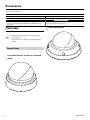
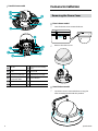
Overview
• Product color and design may vary depending
on the model.
• For more details on each part name, refer to the
manual.
Dome Cover
Plastic dome model / IR LED non-supported
model
Vandal dome model
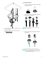
Accessories
Upon purchasing the product, check inside the box to make sure all the following accessories are included. Some parts may dier
depending on the situation.
Item
Network Camera Quick Guide
Terminal Blocks (2 ea.) Screws, Anchors (each 3 ea.)
Guide Pattern
Allen Wrench
Vandal dome model only
RJ45 moduler jack, RJ45 waterproof rubber ring, RJ45 connector
protect cover, cable waterproof rubber ring, RJ45 connector
back cover
Desiccant
Vandal dome model only

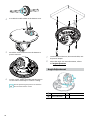
5Network Camera
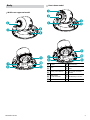
Body
IR LED non-supported model
2
3
0
9
5
5
8
7
6
Plastic dome model
1
2
3
6
0
9
5
8
7
5
1
IR LED
7
Network Port
2
Lens
8
Dome Cover Assembly
Part
3
Factory Reset Button
9
Alarm I/O, Video Out
(CVBS)
5
Wall/Ceiling
Installation Hole
0
SD Memory Card Slot
6
Power

6 Quick Guide
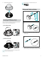
Vandal dome model
1
2
3
6
0
5
5
7
!
@
@
#
9
1
IR LED
8
Dome Cover Assembly
Part
2
Lens
9
Alarm I/O
3
Factory Reset Button
0
SD Memory Card Slot
5
Wall/Ceiling
Installation Hole
!
Cable Rubber
6
Power
@
Network Port
7
Network Port
#
Video Out (CVBS)
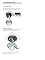
Camera Installation
Removing the Dome Cover
Plastic dome model
1
Turn the dome cover counterclockwise.
2
Remove the dome cover.
Vandal dome model
1
Loosen the screws counterclockwise using the
Allen wrench provided with the product.

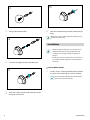
7Network Camera
2
Remove the dome cover.
Inserting a SD Memory Card
Insert a SD memory card into the SD memory card slot
with the ‘micro SD’ print facing upward.
Plastic dome model
micro
SD
Vandal dome model
micro
SD
micro
SD
Push the SD memory card until it disengages from
the slot, and then pull it out.
micro SD Logo is a trademark of SD-3C, LLC.
Waterproof Cable Installation
1
2
3
4
5
6
RJ45 waterproof rubber ring
RJ45 modular jack
RJ45 connector protect cover
cable waterproof rubber ring
(The waterproof rubber ring is fastened to the connector protect cover.)
RJ45 connector back cover
1
Insert a round rubber ring (silicone rubber) into
the RJ45 jack.
1
2
3
4
5
6
RJ45 waterproof rubber ring
RJ45 modular jack
RJ45 connector protect cover
cable waterproof rubber ring
(The waterproof rubber ring is fastened to the connector protect cover.)
RJ45 connector back cover
2
Insert the network cable into the waterproof cap,
rubber bushing, and waterproof cap body in order.

8 Quick Guide
1
2
3
4
5
6
RJ45 waterproof rubber ring
RJ45 modular jack
RJ45 connector protect cover
cable waterproof rubber ring
(The waterproof rubber ring is fastened to the connector protect cover.)
RJ45 connector back cover
3
Plug in the network cable.
1
2
3
4
5
6
RJ45 waterproof rubber ring
RJ45 modular jack
RJ45 connector protect cover
cable waterproof rubber ring
(The waterproof rubber ring is fastened to the connector protect cover.)
RJ45 connector back cover
4
Connect the plug terminal to the RJ45 jack.
1
2
3
4
5
6
RJ45 waterproof rubber ring
RJ45 modular jack
RJ45 connector protect cover
cable waterproof rubber ring
(The waterproof rubber ring is fastened to the connector protect cover.)
RJ45 connector back cover
5
Push the waterproof cap body and cap into the
RJ45 jack and rotate it.
1
2
3
4
5
6
RJ45 waterproof rubber ring
RJ45 modular jack
RJ45 connector protect cover
cable waterproof rubber ring
(The waterproof rubber ring is fastened to the connector protect cover.)
RJ45 connector back cover
6
Lock the waterproof cap into the waterproof cap
body.
Water may seep in and damage the product, if not
pulling the cable back..
Installation
• Check the wall or ceiling to see if it needs to be
reinforced. The camera may fall o if the wall
or ceiling is not strong enough to support its
weight.
• Install the camera in a shaded area. If the camera
is installed in direct sunlight, it may be aected
adversely.
Plastic dome model
1
Use the screws, anchor provided with the camera
to secure the install body on a wall or a ceiling.
Use the provided guide pattern to check the
distance between the screws.

9Network Camera
2
Connect external devices, the network cable, and
the power adapter.
3
Adjust the angle. For more information, refer to
the Angle Adjustment.
Vandal dome model
1
Detach the protrusion part from the cable rubber
along the dotted line.
2
Make the LAN cable go through the cable rubber
using the protect connector.
It is recommended to use lubricant to move the
LAN cable smoothly.
3
Pull the cable slightly and arrange the rubber as
shown below.
To pass through a thin cable or more than two
cables, it is advised to nish it using silicon to make
sure waterproofed perfectly. (Silicon nishing part
— refer to the bottom image.)

10
4
Assemble the cable rubber to the bottom cover.
5
Attach the enclosed desiccant in the bottom to
prevent moisture.
6
Use the screws, anchor provided with the camera
to secure the install body on a wall or a ceiling.
Use the provided guide pattern to check the
distance between the screws.
7
Connect external devices, the network cable, and
the power adapter.
8
Adjust the angle. For more information, refer to
the Angle Adjustment.
Angle Adjustment
3
2
1
1
Lens Rotation
3
Horizontal Rotation
2
Vertical Rotation

11
Closing the Dome Cover
Plastic dome model
Attach the dome cover to the bottom cover. Turn the
dome cover clockwise to fasten the dome cover.
Vandal dome model
Fasten the screws for the dome cover clockwise using
the Allen wrench provided with the camera.
Remove the protective lm inside and outside
before closing the dome cover.

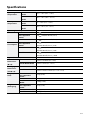
Specications
Operating
Temperature
Plastic Dome
Model
-10°C ~ +50°C (14°F ~ +122°F)
Vandal Dome
Model
-40°C ~ +55°C (-40°F ~ +131°F)
Boot Up
Temperature
Plastic Dome
Model
0°C ~ +50˚C (32°F ~ +122˚F)
Vandal Dome
Model
-20°C ~ +55˚C (-4°F ~ +131˚F)
Operating Humidity
0% ~ 90%
Power Source Plastic Dome model
12V , PoE(IEEE 802.3af, Class3)
Plastic Dome–IR LED
non-supported
model
12V , PoE(IEEE 802.3af, Class2)
Vandal Dome Model
12V , PoE(IEEE 802.3af, Class3)
Power
Consumption
Plastic Dome–IR LED
non-supported
model
12V , 0.38A, 4.6W
PoE, IEEE 802.3af (Class 2), 4.7W
Plastic Dome Model
12V , 0.64A, 7.7W
PoE, IEEE 802.3af (Class 3), 7.6W
Vandal Dome Model
12V , 0.95A, 11.4W
PoE, IEEE 802.3af (Class 3), 10.3W
Approval
FCC, IK10
External
Dimensions
(Ø x H)
Plastic Dome Model
122mm x 103.40mm (4.8" x 4.07")
Vandal Dome Model
155mm x 105mm (6.1" x 4.13")
Packaging
Dimensions
(W x H x D)
Plastic Dome Model
195mm X 150mm X 130mm (76.77" x 59.05" x 51.18")
Vandal Dome Model
211mm x 186mm x 135mm (8.3" x 7.32" x 5.31")
Weight (Main
Unit)
Plastic Dome–IR LED
non-supported
model
0.35kg (0.77lb)
Plastic Dome Model
0.37kg (0.81lb)
Vandal Dome
Model
1.044kg (2.30lb)
Weight
(Packaging)
Plastic Dome–IR LED
non-supported
model
0.53kg (1.17lb)
Plastic Dome Model
0.54kg (1.19lb)
Vandal Dome Model
1.289kg (2.84lb)
V1.3


COSTAR VIDEO SYSTEMS
101 Wrangler Drive, Suite 201 Coppell, Texas 75019
Phone: (469) 635-6800 Fax: (469) 635-6822
Toll-free: (888) 694-7827
-
 1
1
-
 2
2
-
 3
3
-
 4
4
-
 5
5
-
 6
6
-
 7
7
-
 8
8
-
 9
9
-
 10
10
-
 11
11
-
 12
12
-
 13
13
-
 14
14
-
 15
15
-
 16
16


Costar CDI2D12FW Quick start guide
- Type
- Quick start guide
- This manual is also suitable for
Ask a question and I''ll find the answer in the document
Finding information in a document is now easier with AI
Related papers
-
Costar CDI2512IFW Quick start guide
-
Costar CDI2D12FW Quick start guide
-
Costar CDI2510IFW Installation guide
-
-
Costar CDI2D28IW Quick start guide
-
-
-
-
-
Other documents
-
 IDIS DC-D4533HRX Quick start guide
-
Geovision GV-UNP2500 User manual
-
 IDIS DC-D3243HRX-N User manual
-
Panasonic Video Surveillance Product Catalog Product Catalog
-
 Apollo creative Dome Light User manual
-
 IDIS DC-D6233HRXL Quick start guide
-
 IDIS DC-S3283WHX User manual
-
Brickcom VD-130A series User manual
-
 IDIS DC-D3C33HRX User manual
-
 IDIS DC-D6233HRXL Technical Manual


