Page is loading ...

USER WEIGHT LIMITATION: 400lbs(181kgs)
SERIAL NUMBER (found on frame):_____________________
OWNER’S MANUAL
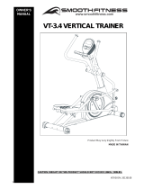
Vertical Trainer
Meijer.com

1
SAFETY INSTRUCTIONS
WARNING: To reduce the risk of serious injury, read the following Safety Instructions before using the
Climber.
1. Read all warnings posted on the Vertical Trainer.
2. Read this Owner's Manual and follow it carefully before using the Vertical Trainer. Make sure that it is properly assembled
and tightened before use.
3. We recommend that two people be available for assembly of this product.
4. Keep children away from the Vertical Trainer. Do not allow children to use or play on the Vertical Trainer. Keep children
and pets away from the Vertical Trainer when it is in use.
5. It is recommended that you place this exercise equipment on an equipment mat.
6. Set up and operate the Vertical Trainer on a solid level surface. Do not position the Vertical Trainer on loose rugs or
uneven surfaces.
7. Inspect the Vertical Trainer for worn or loose components prior to use.
8. Tighten/replace any loose or worn components prior to using the Vertical Trainer.
9. Consult a physician prior to commencing an exercise program. If, at any time during exercise, you feel faint, dizzy, or
experience pain, stop and consult your physician.
10. Follow your physician's recommendations in developing your own personal fitness program.
11. Always choose the workout which best fits your physical strength and flexibility level. Know your limits and train within them.
Always use common sense when exercising.
12. Before using this product, please consult your personal physician for a complete physical examination.
13. Do not wear loose or dangling clothing while using the Vertical Trainer.
14. Never exercise in bare feet or socks; always wear correct footwear, such as running, walking, or cross-training shoes.
15. Be careful to maintain your balance while using, mounting, dismounting, or assembling the Vertical Trainer, loss of
balance may result in a fall and serious bodily injury.
16. Keep both feet firmly and securely on the Foot Pedals while exercising.
17. The Vertical Trainer should not be used by persons weighing over 400 pounds /181 kgs.
18. The Vertical Trainer should be used by only one person at a time.
19. Use two people to assemble and move the Vertical Trainer.
20. Maintenance: Replace the defective components immediately and/or keep the equipment out of use until repair the
equipment completely.
21. Make sure that adequate space is available for access to and passage around the Vertical Trainer; keep at least a
distance of 1 meter from any obstruction object while using the machine.
22. The Vertical Trainer is well-suited to commercial usage.
WARNING: Before starting any exercise or conditioning program you should consult with your personal physician to see if
you require a complete physical exam. This is especially important if you are over the age of 35, have never exercised before,
are pregnant, or suffer from any illness.
READ AND FOLLOW THE SAFETY PRECAUTIONS. FAILURE TO FOLLOW THESE
INSTRUCTIONS CAN RESULT IN SERIOUS BODILY INJURY.
Meijer.com

2
“BEFORE YOU BEGIN”
Thank you for choosing the Vertical Trainer. We take
great pride in producing this quality product and hope
it will provide many hours of quality exercise to make
you feel better, look better and enjoy life to its fullest.
Yes, it's a proven fact that a regular exercise
program can improve your physical and mental health.
Too often, our busy lifestyles limit our time and
opportunity to exercise. The Vertical TVertical
Trainerrainer provides a convenient and simple
method to begin your assault on getting your body in
shape and achieving a happier and healthier lifestyle.
Before reading further, please review the drawing
below and familiarize yourself with the parts that are
labeled. Read this manual carefully before using the
Vertical Trainer.
Console
Accessory
Tray
Dual Handlebar
Pedal
Stationary
Handrail
Leveler
Non-Slip Pad
Sliding Rail
Cover
Meijer.com

3
“HARDWARE IDENTIFICATION CHART”
Unpack the box in a clear area. Use the List of Hardware below to check the contents of the hardware kit. This chart is
provided to help identify the hardware used in the assembly process. Place the washers, the end of bolts, or screws on the
circles to check for the correct diameter. Use the ruler to check the length of the bolts and screws.
THE FOLLOWING TOOLS ARE INCLUDED FOR ASSEMBLY:
NOTICE: The length of all bolts and screws except those with flat heads is
measured from below the head to the end of the bolt or screw. Flat head
bolts and screws are measured from the top of the head to the end of the
bolt or screw.
T-HAND SOCKET
WRENCH (17mm)
SOCKET WRENCH
(13mm)
WRENCH (17mm)
PHILLIPS
SCREWDRIVER (6mm)
Meijer.com

4
“HARDWARE IDENTIFICATION CHART”
After unpacking the unit, you will notice that the package includes 2 bags of hardware (HARDWARE KIT A and
HARDWARE KIT B).
Assembly’s Step 1,4,6: Using HARDWARE KIT A
Assembly’s Step 8,9,10,11,12,14,15: Using HARDWARE KIT B
Note:
a. Please review below to know the content of each hardware kit (A and B)
b. Some small parts may have been pre-attached for shipping. If a part is not in the hardware bag, check to see if it has
been pre-assembled
HARDWARE KIT
A
Part No. and Description Q’TY
111 Lock Washer (M8) 2
114 Washer (8x38x2.0t) 2
134 Bolt (M8xp1.25x10mm) 8
141 Bolt (M8xp1.25x65mm) 2
143 Bolt (M10xp1.5x50mm) 2
HARDWARE KIT B
Part No. and Description Q’TY
121 Screw (M4x20mm) 7
125 Bolt (M5xp0.8x15mm) 18
126 Bolt (M5xp0.8x30mm) 2
Meijer.com

5
“ASSEMBLY PARTS”
Console & Console
Bracket
Handlebar
Decoration Cover
Top & Bottom
Handrail Cover
Rotator Cuff –
Pivoting Arm
Front & Rear
Linkage Cover
Bottom Roller
Bracket
Leveler
Rear Base Frame
Cover & Front
Decoration Cover
Accessory Tray &
Support Pad
Front & Rear
Stabilizer
Upper Handlebar U-Shaped Handlebar
U-Shaped Handlebar
Stand
Pedal & Non-Slip
Pad
Linkage
Console Fixed Plate Upright Post
Long Stationary
Handrail
Main Frame
Pedal Support Arm
Unpack the box in a clear area. Follow the List of Assembly Parts below to check
and make sure all assembly parts are present and in good condition. Do not dispose
of the packing material until the assembly process is completed. Assembly tools and
hardware kit have included for you to use when assembling the product
Meijer.com

6
“ASSEMBLY INSTRUCTIONS”
Place all parts from the box in a cleared area and position them on the floor in front of you. Remove all packing materials
from your area and place them back into the box. Do not dispose of the packing materials until assembly is completed.
Read each step carefully before beginning.
S
TEP 1 – Leveler & Front Stabilizer Assembly
a. Tighten one Leveler (37) under the middle of the
Main Frame (1.) NOTE: It will be easier to attach
the Leveler (37) under the Main Frame (1) by
placing one Styrofoam (or any stationary object)
under one side of the Main Frame (1).
b. Attach 4pcs Levelers (37) to the Front Stabilizer
(2) and the Rear Stabilizer (3).
c. Be sure to tighten the Levelers (37) securely against the Stabilizers (2, 3)
until screw lines are eliminated as the drawing 1 shown on the top right
corner. NOTE: In order to assemble the Stabilizer (2, 3) smoothly, it is
suggested to place one Styrofoam (or any stationary object) under one side
of the Main Frame. If the item is not level, review the LEVELING NOTE on
the right side to level the Levelers (37).
d. Attach the Front Stabilizer (2) onto the Main Frame (1) and secure with
2pcs Washers (8x38x2.0t)(114), 2pcs Lock Washers (M8)(111) and 2pcs
Bolts (M8xp1.25x65mm)(141).
STEP 2 – Rear Stabilizer and Rear Base Frame Cover
Assembly
NOTE: For shipping purpose, 4pcs Bolts
(M8xp1.25x65mm) (137), 4pcs Nylon Nuts (M8xp1.25)(152) are attached on the Rear
Stabilizer (3) as the draft shown on the left.
a. Remove 4pcs Bolts (M8xp1.25x65mm)(137) and 4pcs Nylon Nuts (M8xp1.25)(152) from
the Rear Stabilizer (3).
b. Attach the Rear Stabilizer (3) onto the Main Frame (1) and secure with 4pcs Bolts
(M8xp1.25x65mm)(137) and 4pcs Nylon Nuts (M8xp1.25)(152).
NOTE: For shipping purpose, 2pcs Bolts (M5xp0.8x15mm)(125) are attached on the end of the Main
Frame (1) as the draft shown on the right.
c. Remove 2pcs Bolts (M5xp0.8x15mm)(125) and then attach the Rear Base Frame Cover (35) onto
the end of the Main Frame (1) and secure with 2pcs Bolts (M5xp0.8x15mm)(125).
Detailed Lever- drawing 1
Detailed Lever- drawing 2
LEVELING NOTE: After placing
the equipment in the intended
location for use, check the stability
of the equipment. If the equipment
is not level, reviewing the
following direction:
Loosen the Leveler (37) to make
the Adjustment Plate become less
tight.
Adjust the Leveler (37) for leveling.
Tighten the Adjustment Plate
securely against the Stabilizer to
lock the Leveler (37) in stable
position as the drawing 2 shown.
Stabilizer
Adjustment Plate
Leveler (37)
Stabilizer
Leveler (37)
Meijer.com

7
“ASSEMBLY INSTRUCTIONS”
STEP 3 – Wire
Assembly
CAUTION: Be careful not
to damage the Wires
(158) while
assembling Step 3 & 4.
a. Refer to FIG.A’s 3
following insert
drawings, in order to
let point A (Middle
Handlebar) and point
B (Pedal Arm
Connector) could
connect nicely, before
attaching the Upright
Post (4) to the Main
Frame (1), make sure
raising point A
(Middle Handlebar) in
45 degree, then plug the Middle Connection Wire (158) into the Lower Connection Wire (159). NOTE: Be careful
not to pinch the wires.
STEP 4 – Upright Post Assembly
a. Check that 2pcs Nylock Nuts (M10xp1.5)(153) have preassembled into the front of the Main Frame (1) as FIG.1
illustration shows (they will not be tight, so that slotted bracket of the upright post will slide between the nut and the
frame).
b. Insert the Upright Post (4) into the Main Frame (1) and secure with 2pcs Bolts (M10xp1.5x50mm)(143) by using the
T-HEAD SOCKET WRENCH as shown.
NOTE: Please do not fully tighten Bolts (143) or Nuts (153) until Step. 10 has
been COMPLETED.
NOTE: Please
do not fully
tighten Bolts
(143) until
Step. 10 for the
easy assembly
NOTE: Do not
remove the
Nuts (153)
during
assembly
Meijer.com

8
“ASSEMBLY INSTRUCTIONS”
STEP 5 – Console Fixed Plate
Assembly
NOTE: For shipping purpose, 4pcs Lock Washers
(M8)(111) and 4pcs Bolts (M8xp1.25x12mm)(169) are
attached to the top of the Upright Post (4).
a. Remove 4pcs Lock Washers (M8)(111) and
4pcs Bolts (M8xp1.25x12mm)(166) from the
top of the Upright Post (4).
b. Attach the Console Fixed Plate (165) to the top of
the Upright Post (4) with secure with 4pcs Lock
Washers (M8)(111) and 4pcs Bolts
(M8xp1.25x12mm)(166).
S
TEP 6 – Linkage and Linkage
Cover Assembly
NOTE: For shipping purpose,
2pcs Bolts (M10xp1.5x70mm)
(145), 2pcs Nylon Nuts
(M10xp1.25)(154) and 8pcs
Bolts (M5xp0.8x15mm)
(125) are attached to the
Linkage (16) as the right draft.
a. Remove 2pcs Bolts (M10xp1.5x70mm) (145), 2pcs
Nylon Nuts (M10xp1.25)(154) and 8pcs Bolts
(M5xp0.8x15mm)(125) from the Linkage (16).
b. Following the drawing’s line
to attach the Linkage (16) to
the Right Pivoting Arm (15A) by securing with 2pcs Bolts (M10xp1.5x70mm) (145), 2pcs Nylon
Nuts (M10xp1.25)(154). NOTE: In order to let the Linkage (16) rotate smoothly, after fully tighten
the Bolts (145) and Nuts (154), please loose the Nuts (154) just 1/8 counterclockwise turn.
c. Attach the Front Linkage Cover – Top (71) and Front Linkage Cover – Bottom (72) to the front of
the Linkage (16) and secure with 4pcs Bolts (M5xp0.8x15mm)(125).
d. Attach the Rear Linkage Cover – Top (73) and Rear Linkage Cover – Bottom (74) to the rear of the Linkage
(16) and secure with 4pcs Bolts (M5xp0.8x15mm)(125).
e. Repeat the above same procedure for the left side.
STEP 7 – Pedal Support Arm, Linkage Cover and Pedal Assembly
NOTE: For shipping purpose, 1pcs Bolt (M10xp1.5x70mm) (145), 1pcs Nylon Nut (M10xp1.5)(154) and 4pcs
Bolts (M5xp0.8x15mm)(125) are attached to the front of the Right Pedal Support Arm (18) as right draft.
a. Remove 1pcs Bolt (M10xp1.5x70mm) (145), 1pcs Nylon Nut (M10xp1.5)(154) and 4pcs Bolts
(M5xp0.8x15mm)(125) from the front of the Right Pedal Support Arm (18).
b. Following the drawing’s line to attach the Right Pedal Support Arm (18) to the bottom of the Right Pivoting Arm (15B) and
secure with 1pcs Bolt (M10xp1.5x70mm) (145) and 1pcs Nylon Nut (M10xp1.5)(154). NOTE: In order to let the Linkage
(16) rotate smoothly, after fully tighten the Bolt (145) and Nut (154), please loose the Nuts (154) just 1/8
counterclockwise turn.
c. Attach the Front Linkage Cover – Top (71) and Front Linkage Cover – Bottom (72) to the Right Pedal Support Arm (18)
and secure with 4pcs Bolts (M5xp0.8x15mm)(125).
NOTE: For shipping purpose, 2pcs Lock Washers (M5)(110) and 2pcs Bolts (M5xp0.8x15mm)(126) are
attached to the rear of the Right Pedal Support Arm (17) as the draft shown on the left
d. Remove 2pcs Lock Washers (M5)(110) and 2pcs Bolts (M5xp0.8x15mm)(125) from the rear of the Right
Pedal Support Arm (18).
e. Refer to FIG 2. Place the roller under the Right Pedal Support Arm (17) onto the Sliding Rail. Then attach
the Bottom Roller Bracket (99) to the bottom of the Top Roller Bracket (98) and secure with 2pcs Lock Washer (M5)(110)
and 2pcs Bolts (M5xp0.8x15mm)(125).
f. Attach Right Pedal (76) onto the iron plate that is located in the middle of the Right Pedal Arm (18) and secure with 4pcs
Bolts (M8xp1.25x10mm)(134). Then place the Non-Slip Pad (75) onto the Right Pedal (76).
g. Repeat the above same procedure for the left side
HARDWARE A
Meijer.com

9
“ASSEMBLY INSTRUCTIONS”
STEP 8 – Wire & Handlebar
Stand Assembly
NOTE: For shipping purpose, 4pcs Lock
Washers (M8)(111) and 4pcs Bolts
(M8xp1.25x16mm)(130) are attached to
U-Shaped
Handlebar Stand
(9) as the draft
shown on the right.
a. Remove 4pcs
Lock Washers (M8)(111) and 4pcs
Bolts (M8xp1.25x16mm)(130) from
the U-Shaped Handlebar Stand (9).
b. Connect the Middle Pulse Sensor
Wire (162) to the Lower Pulse
Sensor Wire (163). NOTE: Be careful
not to pinch the wires.
c. Attach U-Shaped Handlebar Stand (9)
to the Upright Post (4) and secure
with 4pcs Lock Washers (M8)(111)
and 4pcs Bolts
(M8xp1.25x16mm)(130).
STEP 9 – Long Stationary Handrail, Aluminum Stand Cover & Handrail Sleeve
Assembly
NOTE: For shipping purpose, 2pcs Lock Washer (M8)(111) and
2pcs Bolt (M8xp1.25x16mm)(130) are attached to bottom of the
U-Shaped Handlebar Stand (9) as FIG.3 shown on the left.
NOTE: For shipping purpose, 4pcs Nylon Nuts (M8xp1.25)(152)
and 4pcs Bolts (M5xp0.8x15mm) (125) are attached to both
sides of the Rear Stabilizer (3) as FIG.4 shown on the right.
Please place all the above pre-attached bolts and washers in a
cleared area and position them on the floor in front of you, these
bolts and washers are for Step 8.
a. Remove 2pcs Lock Washer (M8)(111) and 2pcs Bolt (M8xp1.25x16mm)(130) from the bottom of the U-Shaped
Handlebar Stand (9).
b. Remove 4pcs Nylon Nuts (M8xp1.25)(152) and 4pcs Bolts (M5xp0.8x15mm) (125) from both sides of the Rear
Stabilizer (3).
c. Attach the upper side of Left and Right Long Stationary Handrail (10,11) to the U-Shaped Handlebar Stand (9)
and secure with 2pcs Lock Washer (M8)(111) and 2pcs Bolt (M8xp1.25x16mm)(130).
d. Then attach the bottom side of Left and Right Long Stationary Handrail (10,11) to the Rear Stabilizer (3) and
secure with 4pcs Nylon Nuts (M8xp1.25)(152).
e. Follow the drawing line, attach the Right Aluminum Stand Cover (60) to the Rear Stabilizer (3) and secure with
2pcs Bolts (M5xp0.8x15mm) (125). And slide the Handrail Sleeve (58) down to cover the open area of the Right
Aluminum Stand Cover (60). Repeat the above same procedure for the left side.
STEP 10 – Front Decoration Upright Cover Assembly
a. Please refer to FIG.4 to go back to fully tighten with 2pcs Bolts (M10xp1.5x50mm)(143) and 2pcs
Nylon Nut (M10xp1.5)(153) with the T-Handle SOCKET WRENCH (17mm).
b. Attach the Front Decoration Upright Cover (40) onto the front of the Main Frame (1) with 2pcs
Bolts (M5xp0.8x30mm)(126).
FIG.3
FIG.4
FIG.
4
HARDWARE B
Meijer.com

10
“ASSEMBLY INSTRUCTIONS”
S
TEP 11 – Wire and Console Assembly
a. Connect the Upper Connection Wire (157) to the Middle Connection Wire (158). NOTE: Be careful not to pinch
the wires.
b. Connect the Upper Pulse Sensor Wire (161) to the Middle Pulse Sensor Wire (162). NOTE: Be careful not to
pinch the wires.
c. Place the Console (45) onto the Upright Post (4) by securing with 4pcs Bolts (M5xp0.8x15mm)(125).
STEP 12 –Console Bracket Assembly
Attach the Console Bracket (47) to the Console (45) and secure with 4pcs Bolts (M5xp0.8x15mm)(125).
S
TEP 13 – Handlebar Decoration Cover Assembly
Attach the Upper Handlebar Decoration Cover (48) and the Lower Handlebar Decoration Cover (49) to the Upright
Post (4) and secure with 3pcs Screws (M4x20mm)(121) and 2pcs Bolts (M5xp0.8x15mm)(125).
HARDWARE B
Meijer.com

11
“ASSEMBLY INSTRUCTIONS”
STEP 14 – U-Shaped Handlebar Assembly
NOTE: For shipping purpose, 4pcs Bolts (M8xp1.25x50mm)(133) and 4pcs Nylon Nuts
(M8xp1.25)(152) are attached to U-Shaped Handlebar (8) as the draft shown on the right.
a. Remove 4pcs Bolts (M8xp1.25x50mm)(133) and 4pcs Nylon Nuts (M8xp1.25)(152) from
the U-Shaped Handlebar (8).
b. Attach the U-Shaped Handlebar (8) to the upper side of the U-Shaped Handlebar Stand
(9) and secure with 4pcs Bolts (M8xp1.25x50mm)(133) and 4pcs Nylon Nuts
(M8xp1.25)(152).
STEP 15 – Handrail Cover Assembly
a. Place the Top Handrail Cover – Left (51) and the Bottom Handrail Cover – Left (52) over the left side of the
U-Shaped Handlebar Stand (9) and secure with 2pcs Screws (M4x20mm)(121).
b. Place the Top Handrail Cover – Right (53) and the Bottom Handrail Cover – Right (54) over the right side of the
U-Shaped Handlebar Stand (8) and secure with 2pcs Screws (M4x20mm)(121).
HARDWARE B
Meijer.com

12
“ASSEMBLY INSTRUCTIONS”
STEP 16 – Upper Handlebar & Rotator Cuff–Pivoting Arm Assembly
NOTE: For shipping purpose, 4pcs Lock Washer (M8)(111) and 4pcs Bolts
(M8xp1.25x16mm)(130) are attached to on the rear of Left Upper Handlebar (12) as the
draft shown on the right.
a. Remove 4pcs Lock Washer (M8)(111) and 4pcs Bolts (M8xp1.25x16mm)(130) are
attached to on the rear of Left Upper Handlebar (12).
b. Attach the Right Upper Handlebar (13) to the Right Pivoting Arm (15) and secure with
4pcs Lock Washer (M8)(111) and 4pcs Bolts (M8xp1.25x16mm)(130).
c. Place the Front Rotator Cuff – Pivoting Arm (63) and the Rear Rotator Cuff –
Pivoting Arm (64) over the Right Upper Handlebar (13). And fasten the Covers (63,
64) together with 4pcs Bolts (M5xp0.8x15mm)(125).
d. Repeat the above same procedure for the left side.
STEP 17 – Accessory Tray Assembly
NOTE: For shipping purpose, 2pcs Bolts (M5xp0.8x30mm)(126)are attached to on the back
of Upright Post (4) as the draft shown on the right.
a. Remove 2pcs Bolts (M5xp0.8x30mm)(126) from the back of Upright Post (4).
b. Place the Accessory Tray Support Pad (41) and Accessory Tray (42) on the Upright
Post (4) and secure with 2pcs Bolts (M5xp0.8x30mm)(126).
**For the final step, make sure all the bolts and nuts are fully tightened before using the item**
STEP 18 – Adaptor Assembly
a. Connect the Adaptor’s Wire (164A) to the connector located on the back side of
the Main Frame (1)
b. Plug the Adaptor’s Wire (164B) into an electrical outlet to light up the console.
HARDWARE B
Meijer.com

13
“OPERATIONAL INSTRUCTIONS”
HOW TO ADJUST CONSOLE ANGLE
To get the best console angle, it’s suggested to use both hands to hold the upper
and lower end of the console (area A or B) and gently adjust the console angle to the
proper position
HOW TO MOVE THE ITEM SAFELY
Hold the Rear Stabilizer (3) up with two hands and tow the item to the desired place
carefully
Make sure the floor is level while towing the item
S
TRIDE LENGTH INFO.
The paten stride length of this item is 23’’
(592mm)
Meijer.com

14
“CONSOLE INSTRUCTIONS”
Congratulations! This product is equipped with the MY SMOOTH Virtual Fitness Trainer. Whether you want to lose
weight, train for a sporting event, or simply maintain a healthy lifestyle, the MY SMOOTH Virtual Fitness Trainer
provides the tools, structure and support you need to be fit and live healthy. The 5 simple steps, outlined in the
customer care kit* are proven to help you lose weight, improve your health, and make positive steps to a healthier
lifestyle. These five steps combined with the tools built into your online account, will provide you with a great start
toward achieving your goals.
To set up your account, refer to the instructions in the Getting Started Guide contained in your Smooth Fitness
customer care kit or visit www.my smoothtrainer.com
*Not all Smooth Fitness products include the Smooth Customer Care Kit
Meijer.com

15
“CONSOLE INSTRUCTIONS”
Power ON
a. Make sure the item’s adaptor is correctly plugged into the socket
b. Pedaling or pressing any keys to active the console. The console display will then light up with a short beep sound,
indicating the console will be ready for use
Power Off
The console would automatically shut off after 5 minutes of inactivity
P
rogram List
MANUAL
P1 WEIGHT LOSS
P2 NOV. INTERVAL
P3 INT. INTERVAL
P4 MOUNTAIN CLIMB
P5 HILL CLIMB
P6 ROLLING HILLS
P7 GRAD. INTERVAL
P8 PLATEAU
P9 ADV. INTERVAL
P10 LADDER
P11 USER 1
P12 USER 2
P13 H.R.C.
P14 H.R.C. INTERVAL
T
ake a few minutes to
review the console
layout. Below is an
overview of the
console’s features and
functions
We recommend that
you use the console to
help vary your workout
routine and keep you
focused on your
process toward your
fitness goals. The
console can become an
important source of
motivation and interest
which will help keep
you on track
Speaker
Meijer.com

16
“CONSOLE INSTRUCTIONS – CONSOLE BUTTONS ”
Console Buttons
a. Press START/PAUSE to begin your exercise
b. Press
START/PAUSE again to stop and pause all functions during your exercise program. All the
data on the display will then pause.
c. Press
START/PAUSE again to resume the program and all the data displayed will continue until
the program has finished.
d. HOLD TO RESET function: Press and hold START/PAUSE, all the data will return to 0 and the
console will return to POWER ON status.
Press ENTER to confirm the program function (PROGRAM, TIME, HEIGHT, WEIGHT, AGE, TARGET
H.R. and LEVEL in each time interval).
Press UP to increase the values of the program function (PROGRAM, TIME, HEIGHT, WEIGHT, AGE,
TARGET H.R. and LEVEL in each time interval).
Press DOWN to decrease the values of the program function (PROGRAM, TIME, HEIGHT, WEIGHT,
AGE, TARGET H.R. and LEVEL in each time interval).
**The button is only suitable
to use when the USB is
plugged into the console**
Press MODE to
review
Calendar Mode.
Hold MODE for a few seconds, to go into Calendar
Mode to edit year/month/date/hour/minute.
Press Start/ Pause /Hold to reset to return to POWER
ON status.
a. PULSE RECOVERY button measures how quickly you return
to a resting heart rate after exercising. You could use this
button to measure improvement as you get into shape.
b. The console will monitor your pulse for 60 seconds and
calculate a HEART RATE RECOVERY value from F1.0 to
F6.0. F1.0 is the Highest; F6.0 is the Lowest (For Reference
Only).
c. The readout should only be used as a comparison between
workouts. It’s recommended to use right after any aerobic
exercise. Stop exercising before starting this function.
d. Your pulse will be displayed in approximately 5 seconds
after the heart symbol “
” is displayed.
NOTE:
If you don’t hold the HEART RATE SENSORS on the handrails with both hands properly, the console’s
HEART RATE value will show “0” and the main screen would show “F6.0” after the console counts down
to zero, If the sensor was unable to read your heart rate. Press stop then press the PULSE RECOVERY
button again. Replace your hands on the pulse sensors.
Calendar Mode
Meijer.com

17
“CONSOLE INSTRUCTIONS – CONSOLE BUTTONS ”
Console Buttons
Speaker Sound System:
To enjoy your workout with music, simply connect any MP3/CD player to the LINE
IN jack on the console.
The console is allowed you to use Headphone or Speakers when listening to the
music.
Turn the Volume Knob (located on the left side of the console) to adjust the proper
sound level.
To record your exercise and health metrics, you must log on
to www.mysmoothtrainer.com
. Then sync your MY Smooth Virtual Fitness Trainer
USB device. Once complete simply plug in the MY Smooth Virtual Fitness Trainer USB
device to you compatible Smooth Fitness exercise machine. Displayed on the
equipment will be , your name, weight height and age. Press “START” button to
begin your workout, the console will record your exercise data automatically, every
20 seconds, to your MY Smooth Virtual Fitness Trainer USB device. After your
exercise session is
complete, Insert the
MY Smooth device in to
the USB port of your
PC or MAC to upload
your data to The MY
Smooth Virtual Fitness
Trainer online health
management program.
The detailed reports show your exercise and health results, trends and
recommendations to better achieve and maintain your fitness goals.
Meijer.com

18
“CONSOLE INSTRUCTIONS”– CONSOLE FUNCTIONS”
Console Functions
CALORIES:
Count Up: Measuring total calories your body burned during
exercise.
Display range: 0 ~ 9999.
SPEED:
Displays the current speed KM/MILE during exercise.
RPM (Rotation Per Minute):
Display range: 0 ~ 999.
TIME:
Count Up: If a target time was not selected, TIME will count
up from 0:00 to maximum 99:59 minutes.
Count Down: If you have set the target time (0:00 ~ 99:00),
the console will count down from that selected target time
down to 0:00.
WATTS:
Displays the current value of Watt during exercise.
Display range: 0 ~ 9999.
DISTANCE:
Count Up: If a target distance was not selected, this would
measure the total distance from 0:00 to 999.9 km/mile.
Count Down: If you have set the target distance, the
console will count down from that selected target distance
down to 0.
: Display POWER SUPPLY status.
HAND PULSE / HEART RATE:
To display your heart rete you must wear the chest belt or
place both of your hands on the Pulse Sensors located on
the Handlebars. Your pulse will be displayed approximately
5 seconds after the heart symbol “
” is displayed.
If you do not wear the chest belt or place your hands
correctly on the pulse sensors, the computer will shut off the
pulse circuit. To reactivate the pulse feature, properly place
your hands back on the Pulse Sensors and the pulse
readout will appear again.
: When the MY SMOOTH USB is plugged into the
console, the USB signal will be displayed on the
console.
Meijer.com

19
“CONSOLE INSTRUCTIONS”– CONSOLE FUNCTIONS”
GENDER:
Display range:
Male:
Female:
AGE:
Display range:
10 ~ 99 years old; in 1 year increments
NOTE: Although the console allows input for age
beginning at 10 years old, the product is not
recommended for use by children.
HEIGHT:
Display range:
3 FEET 4 INCHES ~ 7 FEET; 1 INCH increments / 101 ~ 214
CM; 1 CM increments; the product is not recommended for
use by children.
WEIGHT:
Display range:
45 ~ 400LBS; 1 LB increments / 20 ~ 181 KGS; 1 KG
increments; the product is not recommended for use by
children.
TARGET H.R.:
Display range:
50 ~ 180 BPM (beats per minute) ; 1 BPM increments.
Meijer.com
/