Supermicro SUPERSERVER 7045W-NTR+ User manual
- Category
- Server barebones
- Type
- User manual
This manual is also suitable for

®
SUPERSERVER 7045W-NTR+
SUPER
USER’S MANUAL
1.0

Manual Revision 1.0
Release Date: December 27, 2007
The information in this User’s Manual has been carefully reviewed and is believed to be accurate.
The vendor assumes no responsibility for any inaccuracies that may be contained in this document,
makes no commitment to update or to keep current the information in this manual, or to notify any
person or organization of the updates. Please Note: For the most up-to-date version of this
manual, please see our web site at www.supermicro.com.
Super Micro Computer, Inc. ("Supermicro") reserves the right to make changes to the product
described in this manual at any time and without notice. This product, including software, if any,
and documentation may not, in whole or in part, be copied, photocopied, reproduced, translated or
reduced to any medium or machine without prior written consent.
IN NO EVENT WILL SUPERMICRO BE LIABLE FOR DIRECT, INDIRECT, SPECIAL, INCIDENTAL,
SPECULATIVE OR CONSEQUENTIAL DAMAGES ARISING FROM THE USE OR INABILITY TO
USE THIS PRODUCT OR DOCUMENTATION, EVEN IF ADVISED OF THE POSSIBILITY OF
SUCH DAMAGES. IN PARTICULAR, SUPERMICRO SHALL NOT HAVE LIABILITY FOR ANY
HARDWARE, SOFTWARE, OR DATA STORED OR USED WITH THE PRODUCT, INCLUDING THE
COSTS OF REPAIRING, REPLACING, INTEGRATING, INSTALLING OR RECOVERING SUCH
HARDWARE, SOFTWARE, OR DATA.
Any disputes arising between manufacturer and customer shall be governed by the laws of Santa
Clara County in the State of California, USA. The State of California, County of Santa Clara shall
be the exclusive venue for the resolution of any such disputes. Super Micro's total liability for
all claims will not exceed the price paid for the hardware product.
FCC Statement: This equipment has been tested and found to comply with the limits for a Class
A digital device pursuant to Part 15 of the FCC Rules. These limits are designed to provide
reasonable protection against harmful interference when the equipment is operated in a commercial
environment. This equipment generates, uses, and can radiate radio frequency energy and, if not
installed and used in accordance with the manufacturer’s instruction manual, may cause harmful
interference with radio communications. Operation of this equipment in a residential area is likely
to cause harmful interference, in which case you will be required to correct the interference at your
own expense.
California Best Management Practices Regulations for Perchlorate Materials: This Perchlorate
warning applies only to products containing CR (Manganese Dioxide) Lithium coin cells. “Perchlorate
Material-special handling may apply. See www.dtsc.ca.gov/hazardouswaste/perchlorate”
WARNING: Handling of lead solder materials used in this
product may expose you to lead, a chemical known to
the State of California to cause birth defects and other
reproductive harm.
Unless you request and receive written permission from Super Micro Computer, Inc., you may not
copy any part of this document.
Information in this document is subject to change without notice. Other products and companies
referred to herein are trademarks or registered trademarks of their respective companies or mark
holders.
Copyright © 2007 by Super Micro Computer, Inc.
All rights reserved.
Printed in the United States of America

iii
Preface
Preface
About This Manual
This manual is written for professional system integrators and PC technicians. It
provides information for the installation and use of the SuperServer 7045W-NTR+.
Installation and maintenance should be performed by experienced technicians
only.
Manual Organization
Chapter 1: Introduction
The fi rst chapter provides a checklist of the main components included with the
server system and describes the main features of the X7DWN+ serverboard and
the SC745TQ-R800 chassis, which comprise the SuperServer 7045W-NTR+.
Chapter 2: Server Installation
This chapter describes the steps necessary to install the SuperServer 7045W-NTR+
into a rack and check out the server confi guration prior to powering up the system.
If your server was ordered without processor and memory components, this chapter
will refer you to the appropriate sections of the manual for their installation.
Chapter 3: System Interface
Refer here for details on the system interface, which includes the functions and
information provided by the control panel on the chassis as well as other LEDs
located throughout the system.
Chapter 4: System Safety
You should thoroughly familiarize yourself with this chapter for a general overview
of safety precautions that should be followed when installing and servicing the
SuperServer 7045W-NTR+.

SUPERSERVER 7045W-NTR+ User's Manual
iv
Chapter 5: Advanced Serverboard Setup
Chapter 5 provides detailed information on the X7DWN+ serverboard, including the
locations and functions of connections, headers and jumpers. Refer to this chapter
when adding or removing processors or main memory and when reconfi guring the
serverboard.
Chapter 6: Advanced Chassis Setup
Refer to Chapter 6 for detailed information on the SC745TQ-R800 server chassis.
You should follow the procedures given in this chapter when installing, removing or
reconfi guring SCSI /SATA or peripheral drives and when replacing system power
supply units and cooling fans.
Chapter 7: BIOS
The BIOS chapter includes an introduction to BIOS and provides detailed informa-
tion on running the CMOS Setup Utility.
Appendix A: BIOS POST Messages
Appendix B: BIOS POST Codes
Appendix C: Intel HostRAID
Appendix D: Adaptec HostRAID
Appendix E: System Specifi cations

v
Preface
Notes

vi
S
UPERSERVER 7045W-NTR+ User's Manual
Table of Contents
Chapter 1 Introduction
1-1 Overview ......................................................................................................... 1-1
1-2 Serverboard Features ..................................................................................... 1-2
Processors ...................................................................................................... 1-2
Memory ........................................................................................................... 1-2
Serial ATA ....................................................................................................... 1-2
PCI Expansion Slots ....................................................................................... 1-2
UIO .................................................................................................................. 1-2
Onboard Controllers/Ports .............................................................................. 1-3
ATI Graphics Controller ................................................................................... 1-3
Other Features ................................................................................................ 1-3
1-3 Server Chassis Features ................................................................................ 1-3
System Power ................................................................................................. 1-3
Front Control Panel ......................................................................................... 1-3
I/O Backplane .................................................................................................. 1-3
Cooling System ............................................................................................... 1-4
1-4 Contacting Supermicro .................................................................................... 1-6
Chapter 2 Server Installation
2-1 Overview ......................................................................................................... 2-1
2-2 Unpacking the System .................................................................................... 2-1
2-3 Preparing for Setup ......................................................................................... 2-1
Choosing a Setup Location ............................................................................. 2-2
Rack Precautions ............................................................................................ 2-2
Server Precautions .......................................................................................... 2-2
Rack Mounting Considerations ....................................................................... 2-3
Ambient Operating Temperature ................................................................ 2-3
Reduced Airfl ow ......................................................................................... 2-3
Mechanical Loading ................................................................................... 2-3
Circuit Overloading ..................................................................................... 2-3
Reliable Ground ......................................................................................... 2-3
2-4 Installing the System into a Rack ................................................................... 2-4
Identifying the Sections of the Rack Rails ..................................................... 2-4
Installing the Chassis Rails ............................................................................. 2-5
Installing the Rack Rails ................................................................................. 2-6
Installing the Server into the Rack .................................................................. 2-7
2-5 Checking the Serverboard Setup .................................................................... 2-8

vii
Table of Contents
2-6 Checking the Drive Bay Setup ........................................................................ 2-8
Chapter 3 System Interface
3-1 Overview ......................................................................................................... 3-1
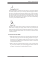
3-2 Control Panel Buttons ..................................................................................... 3-1
Power .............................................................................................................. 3-1
Reset ............................................................................................................... 3-1
3-3 Control Panel LEDs ........................................................................................ 3-2
Power .............................................................................................................. 3-2
HDD ................................................................................................................. 3-2
NIC1 ................................................................................................................ 3-2
NIC2 ................................................................................................................ 3-2
Overheat/Fan Fail ........................................................................................... 3-3
Power Fail ....................................................................................................... 3-3
3-4 Drive Carrier LEDs ......................................................................................... 3-3
Chapter 4 System Safety
4-1 Electrical Safety Precautions .......................................................................... 4-1
4-2 General Safety Precautions ............................................................................ 4-2
4-3 ESD Precautions ............................................................................................. 4-3
4-4 Operating Precautions .................................................................................... 4-4
Chapter 5 Advanced Serverboard Setup
5-1 Handling the Serverboard ............................................................................... 5-1
Precautions ..................................................................................................... 5-1
Unpacking ....................................................................................................... 5-2
5-2 Serverboard Installation .................................................................................. 5-2
5-3 Connecting Cables .......................................................................................... 5-3
Connecting Data Cables ................................................................................. 5-3
Connecting Power Cables .............................................................................. 5-3
Connecting the Control Panel ......................................................................... 5-3
5-4 I/O Ports .......................................................................................................... 5-4
5-5 Installing the Processor and Heat Sink .......................................................... 5-5
5-6 Installing Memory ............................................................................................ 5-9
Memory Support .............................................................................................. 5-9
5-7 Adding PCI Add-On Cards ............................................................................ 5-10
5-8 Serverboard Details .......................................................................................5-11
X7DWN+ Quick Reference ........................................................................... 5-12
5-9 Connector Defi nitions ................................................................................... 5-13
5-10 Jumper Settings ............................................................................................ 5-19
5-11 Onboard Indicators ........................................................................................ 5-23

viii
S
UPERSERVER 7045W-NTR+ User's Manual
5-12 Floppy, IDE, and SATA Ports ........................................................................ 5-24
Chapter 6Advanced Chassis Setup
6-1 Static-Sensitive Devices .................................................................................. 6-1
Precautions ..................................................................................................... 6-1
6-2 Front Control Panel ......................................................................................... 6-3
6-3 System Fans ................................................................................................... 6-4
Fan Failure ...................................................................................................... 6-4
6-4 Drive Bay Installation ...................................................................................... 6-6
SATA Drives .................................................................................................... 6-6
SATA Backplane .............................................................................................. 6-7
Storage Module ............................................................................................... 6-9
Adding Drives to the Storage Module ...................................................... 6-10
Using a Mobile Rack ..................................................................................... 6-10
6-5 Power Supply .................................................................................................6-11
Power Supply Failure .....................................................................................6-11
Removing/Replacing the Power Supply .........................................................6-11
Chapter 7 Advanced Serverboard Setup
7-1 Introduction ...................................................................................................... 7-1
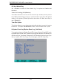
7-2 Running Setup .............................................................................................. 7-2
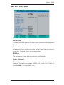
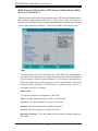
7-3 Main BIOS Setup ............................................................................................ 7-2
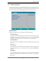
7-4 Advanced Setup .............................................................................................. 7-7
7-5 Security ......................................................................................................... 7-24
7-6 Boot ............................................................................................................... 7-25
7-7 Exit ................................................................................................................ 7-26
Appendix A BIOS POST Messages
Appendix B BIOS POST Codes
Appendix C Intel HostRAID Setup Guidelines
Appendix D Adaptec HostRAID Setup Guidelines
Appendix E System Specifi cations

Chapter 1
Introduction
1-1 Overview
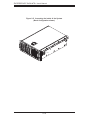
The SuperServer 7045W-NTR+ is a high-end server that is comprised of two main
subsystems: the SC745TQ-R800 tower/4U server chassis and the X7DWN+ dual
Intel Xeon processor serverboard. Please refer to our web site for information on
operating systems that have been certifi ed for use with the SuperServer 7045W-
NTR+ (www.supermicro.com).
In addition to the serverboard and chassis, various hardware components have
been included with the SuperServer 7045W-NTR+, as listed below:
Two (2) CPU passive heatsinks (SNK-P0025P)
Three (3) 8-cm hot-swap chassis fans (FAN-0072L)
Two (2) 8-cm hot-swap rear exhaust fans (FAN-0081L)
One (1) air shroud (CSE-PT0110)
One (1) 3.5" fl oppy drive [FPD-PNSC-02(01)]
Two (2) 5.25" dummy drive trays
One (1) cable for DVD drive (CBL-0139L)
One (1) fl oppy cable (CBL-040L)
One (1) front control panel cable (CBL-0087)
One (1) I/O shield (CSE-PT55)
SATA Accessories
One (1) SATA backplane (CSE-SAS-743TQ)
Six (6) SATA cables (CBL-0061L)
Two (2) SATA LED cables (CBL-0157L)
Eight (8) SATA hot-swap drive carriers [CSE-PT17(B)]
One (1) rackmount kit [CSE-PT026(B)] (optional)
•
•
•
•
•
•
•
•
•
•
•
•
Chapter 1: Introduction
1-1

1-2
S
UPERSERVER 7045W-NTR+ User's Manual
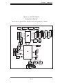
1-2 Serverboard Features
At the heart of the SuperServer 7045W-NTR+ lies the X7DWN+, a dual processor
serverboard based on the Intel 5400 chipset and designed to provide maximum
performance. Below are the main features of the X7DWN+. (See Figure 1-1 for a
block diagram of the 5400 chipset).
Processors
The X7DWN+ supports single or dual LGA771 type Intel Xeon 5400/5300/5200/5100
Sequence processors at a FSB speed of 1600/1333/1066 MHz. Please refer to the
serverboard description pages on our web site for a complete listing of supported
processors (www.supermicro.com).
Memory
The X7DWN+ has sixteen 240-pin DIMM slots that can support up to 128 GB of
FBD (Fully Buffered DIMM) ECC DDR2-800/667/533 SDRAM. Both 1.5V and 1.8V
memory are supported (but cannot be mixed). The memory operates in a 4-way
interleaved confi gurations and requires requires modules of the same size and
speed to be installed two at a time. See Chapter 5 for details.
Serial ATA
A SATA controller is integrated into the ESB2 (South Bridge) portion of the 5400
chipset to provide a six-port 3 Gb/s Serial ATA subsystem, which is RAID 0, 1, 10
and 5 supported. The Serial ATA drives are hot-swappable units.
Note: The operating system you use must have RAID support to enable the hot-
swap capability and RAID function of the Serial ATA drives.
PCI Expansion Slots
The X7DWN+ has three PCI-Express x8 slots (two are Gen 2), one PCI-Express x4
slot (in a x8 slot), two 64-bit 133/100 MHz PCI-X slots and one UIO slot (see below).
One PCI-Express x8 slot has an SEPC connector for a 2U active riser card.
UIO
The X7DWN+ is a specially-designed serverboard that features Supermicro's UIO
(Universal I/O) technology. UIO serverboards have a PCI-Express x8 connector
that can support any one of several types of UIO card types to add SAS ports,
additional LAN ports, etc. to the serverboard. This allows the user to tailor the
serverboard to their own needs. Note: the 7045W-NTR+ does not come with a
UIO card installed.

1-3
Chapter 1: Introduction
Onboard Controllers/Ports
One fl oppy drive connector and two onboard ATA/100 connectors (one reserved
for the use of a compact fl ash card) are provided to support IDE hard drives or
ATAPI devices. The color-coded I/O ports include one COM port (an additional COM
header is located on the serverboard), a VGA (monitor) port, two USB 2.0 ports
(three additional USB headers are included on the serverboard), PS/2 mouse and
keyboard ports and two gigabit Ethernet ports.
ATI Graphics Controller
The X7DWN+ features an integrated ATI video controller based on the ES1000 32
MB graphics chip. The ES1000 was designed specifi cally for servers, featuring low
power consumption, high reliability and superior longevity.
Other Features
Other onboard features that promote system health include onboard voltage moni-
tors, a chassis intrusion header, auto-switching voltage regulators, chassis and CPU
overheat sensors, virus protection and BIOS rescue.
1-3 Server Chassis Features
The following is a general outline of the main features of the SC745TQ-R800 server
chassis.
System Power
The SC745TQ-R800 features a redundant 800W power supply composed of two
separate power modules. This power redundancy feature allows you to replace a
failed power supply without shutting down the system.
Front Control Panel
The control panel on the SuperServer 7045W-NTR+ provides you with system
monitoring and control. LEDs indicate system power, HDD activity, network activity,
system overheat and power supply failure. A main power button and a system reset
button are also included. In addition, two USB ports have been incorporated into
the control panel to provide front side USB access.
I/O Backplane
The SC745TQ-R800 is an Extended ATX form factor chassis that may be used in
either a tower or a 4U rackmount confi guration. The I/O backplane provides seven

1-4
S
UPERSERVER 7045W-NTR+ User's Manual
tool-less motherboard expansion slots, one COM port, one parallel port, one VGA
port, two USB 2.0 ports, PS/2 mouse and keyboard ports and two gigabit Ethernet
ports.
Cooling System
The SC745TQ-R800 chassis has an innovative cooling design that includes three
8-cm hot-plug system cooling fans located in the middle section of the chassis as
well as two 8-cm hot-plug exhaust fans located at the rear of the chassis. An air
shroud channels the airfl ow from the system fans to effi ciently cool the processor
area of the system. The power supply module also includes a cooling fan.

1-5
Chapter 1: Introduction
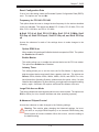
Figure 1-1. Intel 5400 Chipset:
System Block Diagram
Note: This is a general block diagram. Please see Chapter 5 for details.
FBD DIMM
FBD DIMM
FBD DIMM
FBD DIMM

1-6
S
UPERSERVER 7045W-NTR+ User's Manual
1-4 Contacting Supermicro
Headquarters
Address: Super Micro Computer, Inc.
980 Rock Ave.
San Jose, CA 95131 U.S.A.
Tel: +1 (408) 503-8000
Fax: +1 (408) 503-8008
Email: [email protected] (General Information)
[email protected] (Technical Support)
Web Site: www.supermicro.com
Europe
Address: Super Micro Computer B.V.
Het Sterrenbeeld 28, 5215 ML
's-Hertogenbosch, The Netherlands
Tel: +31 (0) 73-6400390
Fax: +31 (0) 73-6416525
Email: [email protected] (General Information)
[email protected] (Technical Support)
[email protected] (Customer Support)
Asia-Pacifi c
Address: Super Micro, Taiwan
4F, No. 232-1, Liancheng Rd.
Chung-Ho 235, Taipei County
Taiwan, R.O.C.
Tel: +886-(2) 8226-3990
Fax: +886-(2) 8226-3991
Web Site: www.supermicro.com.tw
Technical Support:
Email: [email protected]
Tel: 886-2-8228-1366, ext.132 or 139

Chapter 2: Server Installation
2-1
Chapter 2
Server Installation
2-1 Overview
This chapter provides a quick setup checklist to get your SuperServer 7045W-NTR+
up and running. Following these steps in the order given should enable you to have
the system operational within a minimum amount of time. This quick setup assumes
that your system has come to you with the processors and memory preinstalled. If
your system is not already fully integrated with a serverboard, processors, system
memory etc., please turn to the chapter or section noted in each step for details
on installing specifi c components.
The 7045W-NTR+ may be employed either as a tower or mounted in a rack as a 4U
rackmount chassis. If using it as a tower unit, please read the Server Precautions
in the next section and then skip ahead to Section 2-5.
2-2 Unpacking the System
You should inspect the box the system was shipped in and note if it was damaged
in any way. If the server itself shows damage you should fi le a damage claim with
the carrier who delivered it.
Decide on a suitable location for the SuperServer 7045W-NTR+. It should be
situated in a clean, dust-free area that is well ventilated. Avoid areas where heat,
electrical noise and electromagnetic fi elds are generated. You will also need it placed
near a grounded power outlet. Be sure to read the Rack and Server Precautions
in the next section.
2-3 Preparing for Setup
The box the system was shipped in may include two sets of rail assemblies, two
rail mounting brackets and mounting screws needed for installing the system into a
rack (optional kit). Follow the steps in the order given to complete the installation
process in a minimum amount of time. Please read this section in its entirety before
you begin the installation procedure outlined in the sections that follow.

2-2
S
UPERSERVER 7045W-NTR+ User's Manual
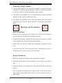
! !
Warnings and Precautions!
Choosing a Setup Location
Leave enough clearance in front of the rack to enable you to open the front door
completely (~25 inches) and approximately 30 inches of clearance in the back
of the rack to allow for suffi cient airfl ow and ease in servicing.
This product is for installation only in a Restricted Access Location (dedicated
equipment rooms, service closets and the like).
This product is not suitable for use with visual display work place devices
acccording to §2 of the the German Ordinance for Work with Visual Display
Units.
•
•
•
Rack Precautions
Ensure that the leveling jacks on the bottom of the rack are fully extended to
the fl oor with the full weight of the rack resting on them.
In single rack installation, stabilizers should be attached to the rack. In multiple
rack installations, the racks should be coupled together.
Always make sure the rack is stable before extending a component from the
rack.
You should extend only one component at a time - extending two or more si-
multaneously may cause the rack to become unstable.
Server Precautions
Review the electrical and general safety precautions in Chapter 4.
Determine the placement of each component in the rack before you install the
rails.
Install the heaviest server components on the bottom of the rack fi rst, and then
work up.
Use a regulating uninterruptible power supply (UPS) to protect the server from
power surges, voltage spikes and to keep your system operating in case of a
power failure.
•
•
•
•
•
•
•
•

Chapter 2: Server Installation
2-3
Allow the hot plug SATA drives and power supply modules to cool before touch-
ing them.
Always keep the rack's front door and all panels and components on the servers
closed when not servicing to maintain proper cooling.
Rack Mounting Considerations
Ambient Operating Temperature
If installed in a closed or multi-unit rack assembly, the ambient operating tempera-
ture of the rack environment may be greater than the ambient temperature of the
room. Therefore, consideration should be given to installing the equipment in an
environment compatible with the manufacturer’s maximum rated ambient tempera-
ture (Tmra).
Reduced Airfl ow
Equipment should be mounted into a rack so that the amount of airfl ow required
for safe operation is not compromised.
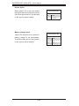
Mechanical Loading
Equipment should be mounted into a rack so that a hazardous condition does not
arise due to uneven mechanical loading.
Circuit Overloading
Consideration should be given to the connection of the equipment to the power
supply circuitry and the effect that any possible overloading of circuits might have
on overcurrent protection and power supply wiring. Appropriate consideration of
equipment nameplate ratings should be used when addressing this concern.
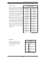
Reliable Ground
A reliable ground must be maintained at all times. To ensure this, the rack itself
should be grounded. Particular attention should be given to power supply connec-
tions other than the direct connections to the branch circuit (i.e. the use of power
strips, etc.).
•
•

2-4
S
UPERSERVER 7045W-NTR+ User's Manual
2-4 Installing the System into a Rack
This section provides information on installing the system into a rack unit. Rack
installation requires the use of the optional rackmount kit. If the system has already
been mounted into a rack or if you are using it as a tower, you can skip ahead to
Sections 2-5 and 2-6.
There are a variety of rack units on the market, which may mean the assembly
procedure will differ slightly. The following is a guideline for installing the server into
a rack with the rack rails provided in the rackmount kit. You should also refer to the
installation instructions that came with the rack unit you are using.
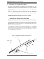
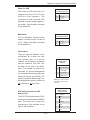
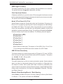
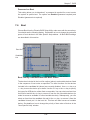
Identifying the Sections of the Rack Rails
The optional rackmount kit includes two rack rail assemblies. Each of these as-
semblies consist of three sections: an inner fi xed chassis rail that secures to the
chassis, an outer rack rail that secures directly to the rack itself and two rail brackets,
which also attack to the rack (see Figure 2-1.) The inner and outer rails must be
detached from each other to install.
To remove the inner chassis rail, pull it out as far as possible - you should hear a
"click" sound as a locking tab emerges from inside the rail assembly and locks the
inner rail. Depress the locking tab to pull the inner rail completely out. Do this for
both assemblies (one for each side).
Figure 2-1. Identifying the Sections of the Rack Rails
Inner rail
Outer rail
Rail brackets

Chapter 2: Server Installation
2-5
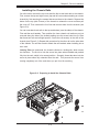
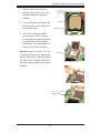
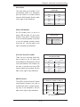
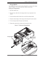
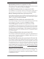
Installing the Chassis Rails
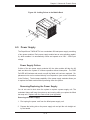
You will need to remove the top cover and the feet to add rack rails to the chassis.
First, remove the top and right covers (top and left covers when standing as a tower
chassis) by fi rst removing the screws that secure them to the chassis. Depress the
button on the top (side if tower) of the chassis to release the cover and then pull
the cover off. Then unscrew the four feet and remove them from the chassis (see
Figure 2-2).
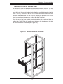
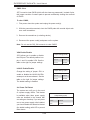
You can now attach rack rails to the top and bottom (now the sides) of the chassis.
First add the rack handles. Then position the inner chassis rail sections you just
removed along the side of the chassis making sure the screw holes line up. Note
that these two rails are left/right specifi c. Screw the rail securely to the side of the
chassis (see Figure 2-3). Repeat this procedure for the other rail on the other side
of the chassis. You will also need to attach the rail brackets when installing into a
telco rack.
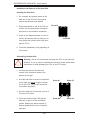
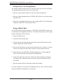
Locking Tabs: As mentioned, the chassis rails have a locking tab, which serves
two functions. The fi rst is to lock the server into place when installed and pushed
fully into the rack, which is its normal position. Secondly, these tabs also lock the
server in place when fully extended from the rack. This prevents the server from
coming completely out of the rack when you pull it out for servicing.
Figure 2-2. Preparing to Install the Chassis Rails

2-6
S
UPERSERVER 7045W-NTR+ User's Manual
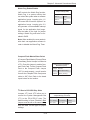
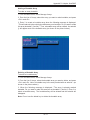
Installing the Rack Rails
Determine where you want to place the SuperServer 7045W-NTR+ in the rack. (See
Rack and Server Precautions in Section 2-3.) Position the fi xed rack rail/sliding rail
guide assemblies at the desired location in the rack, keeping the sliding rail guide
facing the inside of the rack. Screw the assembly securely to the rack using the
brackets provided. Attach the other assembly to the other side of the rack, making
sure both are at the exact same height and with the rail guides facing inward.
Figure 2-3. Installing the Rails to the Chassis
Page is loading ...
Page is loading ...
Page is loading ...
Page is loading ...
Page is loading ...
Page is loading ...
Page is loading ...
Page is loading ...
Page is loading ...
Page is loading ...
Page is loading ...
Page is loading ...
Page is loading ...
Page is loading ...
Page is loading ...
Page is loading ...
Page is loading ...
Page is loading ...
Page is loading ...
Page is loading ...
Page is loading ...
Page is loading ...
Page is loading ...
Page is loading ...
Page is loading ...
Page is loading ...
Page is loading ...
Page is loading ...
Page is loading ...
Page is loading ...
Page is loading ...
Page is loading ...
Page is loading ...
Page is loading ...
Page is loading ...
Page is loading ...
Page is loading ...
Page is loading ...
Page is loading ...
Page is loading ...
Page is loading ...
Page is loading ...
Page is loading ...
Page is loading ...
Page is loading ...
Page is loading ...
Page is loading ...
Page is loading ...
Page is loading ...
Page is loading ...
Page is loading ...
Page is loading ...
Page is loading ...
Page is loading ...
Page is loading ...
Page is loading ...
Page is loading ...
Page is loading ...
Page is loading ...
Page is loading ...
Page is loading ...
Page is loading ...
Page is loading ...
Page is loading ...
Page is loading ...
Page is loading ...
Page is loading ...
Page is loading ...
Page is loading ...
Page is loading ...
Page is loading ...
Page is loading ...
Page is loading ...
Page is loading ...
Page is loading ...
Page is loading ...
Page is loading ...
Page is loading ...
Page is loading ...
Page is loading ...
Page is loading ...
Page is loading ...
Page is loading ...
Page is loading ...
Page is loading ...
Page is loading ...
Page is loading ...
Page is loading ...
Page is loading ...
Page is loading ...
Page is loading ...
Page is loading ...
Page is loading ...
Page is loading ...
Page is loading ...
Page is loading ...
Page is loading ...
Page is loading ...
Page is loading ...
Page is loading ...
Page is loading ...
Page is loading ...
Page is loading ...
Page is loading ...
Page is loading ...
Page is loading ...
Page is loading ...
Page is loading ...
Page is loading ...
Page is loading ...
Page is loading ...
Page is loading ...
Page is loading ...
Page is loading ...
Page is loading ...
Page is loading ...
Page is loading ...
Page is loading ...
Page is loading ...
Page is loading ...
Page is loading ...
Page is loading ...
Page is loading ...
Page is loading ...
Page is loading ...
Page is loading ...
-
 1
1
-
 2
2
-
 3
3
-
 4
4
-
 5
5
-
 6
6
-
 7
7
-
 8
8
-
 9
9
-
 10
10
-
 11
11
-
 12
12
-
 13
13
-
 14
14
-
 15
15
-
 16
16
-
 17
17
-
 18
18
-
 19
19
-
 20
20
-
 21
21
-
 22
22
-
 23
23
-
 24
24
-
 25
25
-
 26
26
-
 27
27
-
 28
28
-
 29
29
-
 30
30
-
 31
31
-
 32
32
-
 33
33
-
 34
34
-
 35
35
-
 36
36
-
 37
37
-
 38
38
-
 39
39
-
 40
40
-
 41
41
-
 42
42
-
 43
43
-
 44
44
-
 45
45
-
 46
46
-
 47
47
-
 48
48
-
 49
49
-
 50
50
-
 51
51
-
 52
52
-
 53
53
-
 54
54
-
 55
55
-
 56
56
-
 57
57
-
 58
58
-
 59
59
-
 60
60
-
 61
61
-
 62
62
-
 63
63
-
 64
64
-
 65
65
-
 66
66
-
 67
67
-
 68
68
-
 69
69
-
 70
70
-
 71
71
-
 72
72
-
 73
73
-
 74
74
-
 75
75
-
 76
76
-
 77
77
-
 78
78
-
 79
79
-
 80
80
-
 81
81
-
 82
82
-
 83
83
-
 84
84
-
 85
85
-
 86
86
-
 87
87
-
 88
88
-
 89
89
-
 90
90
-
 91
91
-
 92
92
-
 93
93
-
 94
94
-
 95
95
-
 96
96
-
 97
97
-
 98
98
-
 99
99
-
 100
100
-
 101
101
-
 102
102
-
 103
103
-
 104
104
-
 105
105
-
 106
106
-
 107
107
-
 108
108
-
 109
109
-
 110
110
-
 111
111
-
 112
112
-
 113
113
-
 114
114
-
 115
115
-
 116
116
-
 117
117
-
 118
118
-
 119
119
-
 120
120
-
 121
121
-
 122
122
-
 123
123
-
 124
124
-
 125
125
-
 126
126
-
 127
127
-
 128
128
-
 129
129
-
 130
130
-
 131
131
-
 132
132
-
 133
133
-
 134
134
-
 135
135
-
 136
136
-
 137
137
-
 138
138
-
 139
139
-
 140
140
-
 141
141
-
 142
142
-
 143
143
-
 144
144
-
 145
145
-
 146
146


Supermicro SUPERSERVER 7045W-NTR+ User manual
- Category
- Server barebones
- Type
- User manual
- This manual is also suitable for
Ask a question and I''ll find the answer in the document
Finding information in a document is now easier with AI
Related papers
-
Supermicro SuperServer 6011D Hardware Install Manual
-
Supermicro MBD-X7DWN+-O User manual
-
-
-
-
-
-
-
SUPER MICRO Computer SUPERSERVER 5015M-U User manual
-
SUPER MICRO Computer 5014C-MF User manual
Other documents
-
DeLOCK 47192 Datasheet
-
HP 6-Port SATA RAID User manual
-
DeLOCK 91635 Datasheet
-
Lindy 20968 Installation guide
-
 IPASON V5 E Sports Gaming Desktop Computer User manual
-
 StarTech.com SBAY5BK Datasheet
-
Adaptec Serial Attached SCSI 48300 User guide
-
Vantec MRK-300ST-BK User manual
-
DT Research DT166LX Basic Operation Manual
-

