Carf-Models Yak 55SP Owner's manual
- Category
- Toys & accessories
- Type
- Owner's manual
This manual is also suitable for

Composite-ARF Yak 55 (2.1m/83”)
Instruction Manual
Composite-ARF Yak 55SP, 2.1m (83”)
TAVS Technology
version 1.0

Instructions for Yak 55SP IMAC-Airplane
Thank you very much for purchasing our Composite-ARF Yak 55SP 2.1m (83” span) all compos-
ite aircraft, made with the revolutionary Total Area Vacuum Sandwich (TAVS) technology
If you want a full-color version of this manual, you can download it free of charge from our web-
site, as an Adobe Acrobat .pdf file and print it. Just go to the Yak 2.1m page on our website, and
click on the link named ‘Download Instruction Manual’ link above the top photo of the product.
NB: Please read all of the important information on pages 3 - 7 of this Instruction Manual
carefully before starting the assembly of your Yak 55, especially if this is one of your
first fully-composite ARF type aircraft.
Before you get started building and setting-up your aircraft, please make sure you have read this
Instruction Manual several times, and understood it. If you have any questions, please don’t
hesitate to contact us. Below are the contact details:
Email: [email protected]
Telephone: Phone your C-ARF Rep!!! He will be there for you.
Website: http://www.composite-arf.com
Liability Exclusion and Damages
You have acquired a kit, which can be assembled into a fully working R/C model when fitted out
with suitable accessories, as described in the instruction manual with the kit.
However, as manufacturers, we at Composite-ARF are not in a position to influence the way you
build and operate your model, and we have no control over the methods you use to install,
operate and maintain the radio control system components. For this reason we are obliged to
deny all liability for loss, damage or costs which are incurred due to the incompetent or incorrect
application and operation of our products, or which are connected with such operation in any
way. Unless otherwise prescribed by binding law, the obligation of the Composite-ARF compa-
ny to pay compensation is excluded, regardless of the legal argument employed.
This applies to personal injury, death, damage to buildings, loss of turnover and business,
interruption of business or other direct and indirect consequent damages. In all circumstances
our total liability is limited to the amount which you actually paid for this model.
BY OPERATING THIS MODEL YOU ASSUME FULL RESPONSIBILITY FOR YOUR ACTIONS.
It is important to understand that CARF-Models Co., Ltd, is unable to monitor whether you
follow the instructions contained in this instruction manual regarding the construction, operation
and maintenance of the aircraft, nor whether you install and use the radio control system
correctly. For this reason we at CARF-Models are unable to guarantee or provide a
contractual agreement with any individual or company that the model you have made will
function correctly and safely. You, as operator of the model, must rely upon your own expertise
and judgement in acquiring and operating this model.
Composite-ARF Yak 55 (2.1m/83”)
2

Important Supplementary Notes
Pre-Assembly Checks:
At Composite-ARF we take every possible precaution to make sure that all our products are
carefully checked before they leave the factory - but of course it is always possible that human
error creeps in occasionally with high-volume production, and that an important part has been
incorrectly installed or glued into position.
Therefore we strongly recommend that you double-check the following critical structural com-
ponents before starting the assembly of your aircraft - and also regularly before every flying ses-
sion as a hard landing, shock loads during transport, or vibrations from unbalanced propellers,
etc., could all damage the glue joints to these critical components that ensure the structural
integrity of your plane, and the safety of people nearby.
1) Check that the plastic wing retaining bolts, and the front and back fibreglass rod anti-
rotation dowels, are securely glued into the wing root ribs. Check that the fibreglass rod
anti-rotation pins are securely glued into the front of the stabiliser root ribs.
2) Check that the fibreglass sleeves for the wing and stab spar tubes are securely glued into
the fuselage.
3) Check that the alloy wing tube and carbon stab tubes are the correct lengths, as shown in
the hardware list at the end of these instructions, not bent or damaged at all, and that they
fit into the sleeves in the fuselage and wings/stabs without too much ‘play’.
4) Check that the plywood landing gear support plates are securely glued to the top of the
muffler tunnel and sides of the fuselage.
Pre-Flight Checks:
Before every session check that all the model’s working systems function correctly, and be sure
to carry out a range check. The first time you fly any new model aircraft we strongly recommend
that you enlist the help of an experienced modeller to help you check the model and offer advice
while you are flying. Be certain to keep to the recommended CG position & control surface trav-
els. If adjustments are required, carry them out before operating the model. Be aware of any
instructions & warnings of other manufacturers, whose product(s) you use to fly this aircraft.
Make sure that your wing and stab spar tubes are not damaged. Check that the anti-rotation pins
for the wings and stabiliser are not loose. Check that the plastic wing retaining nuts are tight, that
the M3 bolts retaining the horizontal stabilisers onto the carbon tube are tight, and that the rud-
der hinge wire cannot come out with a piece of clear tape.
Please don’t ignore our warnings, or those provided by other manufacturers. They refer to things
and processes which, if ignored, could result in permanent damage or fatal injury
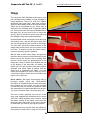
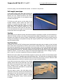
Attention !
This IMAC-Aircraft is a high-end product & can create an enormous risk for both pilot and spec-
tators, if not handled with care, and used according to the instructions. Make sure that you oper-
ate your Yak according to the laws and regulations governing model flying in the country of use.
The engine, servos and control surfaces have to be attached properly. Please use only the
recommended engines, servos, propellers, and accessories. Make sure that the ‘Centre of
Gravity’ is located in the recommended place. Use the nose heavy end of the CG range for your
first flights. A tail heavy plane, especially during the first flight, can be an enormous danger for
you and all spectators. Fix all heavy items, like batteries, very securely into the plane.
Composite-ARF Yak 55 (2.1m/83”)
3

Composite-ARF Yak 55 (2.1m/83”)
4
Make sure that the plane is secured properly
when you start up the engine. Have a helper hold
your plane from the tail end, or from behind the
wing tips, before you start the engine. Make sure
that all spectators are behind, or far in front, of the
aircraft when running up the engine.
Make sure that you range check your R/C system
thoroughly before the 1st flight. It is absolutely
necessary to range check your complete R/C
installation first WITHOUT the engine running.
Leave the transmitter antenna retracted, and
check the distance you can walk before ‘fail-safe’
occurs. Then start up the engine, run it at about
half throttle and repeat this range check with the engine running. Make sure that there is no
range reduction before ‘fail-safe’ occurs. Only then make the 1st flight. If the range with engine
running is less then with the engine off, please contact the radio supplier/engine manufacturer
and DON’T FLY at that time.
Check for vibrations through the whole throttle range. The engine should run smoothly with no
unusual vibration. If you think that there are any excessive vibrations at any engine rpm’s, DON’T
FLY at this time and check your engine, spinner and propeller for proper balancing. The light-
weight sandwich composite parts don’t like too much vibration and they can suffer damage. The
low mass of all the parts results in a low physical inertia, and any excess vibrations can affect
the servos and linkages.
General Information about
fully-composite aircraft structure
All the parts are produced in negative molds, manufactured using vacuum-bagged sandwich
construction technology. All parts are painted in the molds, either single color or designer
schemes. A production method called TAVS (Total Area Vacuum Sandwich), enables us to pres-
ent this aircraft with incredible built-in strength, while still being lightweight, and for a price that
nobody could even consider some years ago. This production process has huge advantages, but
a few disadvantages also. These facts need to be explained in advance for your understanding.
Description of Parts
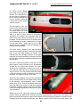
The Wings:
The wings are made in negative moulds, fully vacuum bagged, using only 2 layers of 2 oz. cloth
in combination with a very hard 2 mm foam sandwich to form a hard and durable outer skin.
The ailerons are elastic-hinged already for you - laminated
in the mould and attached to the wing with a special nylon
hinge-cloth, sandwiched between the outer skin and the
foam. This nylon hinge is 100% safe and durable. You will
never have to worry about breaking it, or wearing it out.
There is no gap at all on the top wing surface, and there is
a very narrow slot in the bottom surface, where the aileron
slides under the main wing skin during down throw. This
means that the hinge axis line is on the top surface of the
NO !!!
NO
NO
DANGER ZONES
Secure the plane
before starting
the engine.

wing, not in the centre. This is NOT a disadvantage, if you
program in about 10% NEGATIVE aileron differential in
your transmitter. This means that the ‘down’ throw needs to
be about 10% more than the up throw. Why? Because the
axis of the hinge is not at the centreline of the aileron, so it
moves slightly in and out when operated, and the aileron
gets a little "smaller" in surface area when moving down.
The bottom slot needs some explanation, too. The cut line
is exactly in the correct position so that the aileron slides under the wing skin smoothly. If the cut
was a few mm forward or back, it would not work properly. So, make sure that the lip is not dam-
aged, and that the aileron slides under this lip perfectly. It will NOT lock at any time, if the lip is
not damaged. If damage occurs to the lip, you can cut off 2-3 mm, but you should NEVER need
to cut off more than this.
The Fuselage:
The fuselage is also made in negative moulds, constructed using TAVS technology. The main
internal structural parts for the landing gear, wing and stab spar supports, etc., are all glued in
during manufacture to ensure accurate location and reduce the assembly time for you. There is
no need to even check the incidences - you can be assured that these are already set in the
molds so that no adjustment is necessary.
The all-composite combined firewall and exhaust tunnel is factory-installed and aligned for your
convenience, and contributes greatly to the strength of the airframe.
The pre-installed landing gear mount is strong and doesn’t need any extra reinforcement. You
have an extremely light weight fuselage, and the gear
loads need to be led into the structure gently. The all-new
landing gear is quite a flexible design, which works very
much like shock absorbers. Do not change or modify it, as
the results would only be negative.
The Stabilisers:
The stab parts are also vacuum bagged sandwiched. The
rudder is hinged with a Ø 2mm steel wire, and the eleva-
tor control surfaces are factory-hinged with proprietary
hinge-points, 4 on each stab.
The rudder and elevator design allows for at least 45°
throw. The horizontal stabs are mounted with one Ø
14mm carbon tube and one 6mm anti-rotation pin each.
Servo Screws:
Fix all the servos into the milled plywood servo mounts
using the 2.9 Ø x13mm sheet metal screws provided in
the kit, not the standard screws normally supplied with
servos by the servo manufacturer. This is because all the
holes in our milled servo mounts are 2mm diameter, due
to our CNC manufacturing process, and this is too big for
the normal screws.
Composite-ARF Yak 55 (2.1m/83”)
5
Centreline of hinge axis
Phenolic control horn

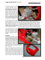
Take Care:
Composite sandwich parts are extremely strong, but fragile
at the same time. Always keep in mind that these contest
airplanes are designed for minimum weight and maximum
strength in flight. Please take care of it, especially when it
is being transported, to make sure that none of the critical
parts and linkages are damaged. Always handle your air-
plane with great care, especially on the ground and during
transport, so you will have many hours of pleasure with it.
Tools and Adhesives
Tools etc:
This is a very quick and easy plane to build, not requiring special techniques or equipment, but
even the building of Composite-ARF aircraft requires some suitable tools. You will probably have
all these tools in your workshop anyway, but if not, they are available in all good hobby shops,
or hardware stores like "Home Depot" or similar.
1. Sharp knife (X-Acto or similar)
2. Allen key set (metric) 2.5mm, 3mm and 4mm.
3. Sharp scissors
4. Pliers (various types)
5. Wrenches (metric)
6. Slotted and Phillips screwdrivers (various sizes)
7. M3 tapping tool (metric)
8. Drills of various sizes
9. Dremel tool (or Proxxon, or similar) with cutting discs, sanding tools and mills.
10. Sandpaper (various grits), and Permagrit sanding tools (high quality).
11. Carpet, bubble wrap or soft cloth to cover your work bench (most important !)
12. Clear Car wax polish (for protecting painted areas close to glue joints).
13. Denaturised alcohol, or similar (for cleaning joints before gluing)
14. An Incidence meter is helpful for engine thrustline alignment.
Adhesives:
Not all types of glues are suited to working with composite parts. Here is a selection of what we
normally use, and what we can truly recommend. Please don’t use low quality glues - you will
end up with an inferior quality plane, that is not so strong or safe.
1. CA-Glue ‘Thin’ and ‘Thick’ types. We recommend ZAP, as this is a very high quality.
2. 5 minute-epoxy (highest quality seems to be Z-Poxy)
3. 30 minute epoxy (stressed joints must be glued with 30 min and NOT 5 min epoxy).
4. Epoxy laminating resin (12 - 24 hr cure) with hardener.
5. Milled glass fibre, for adding to slow epoxy for strong joints.
6. Microballoons, for adding to slow epoxy for lightweight filling.
We take great care during production and Quality Control at the factory to ensure that all joints
are properly glued, but strongly recommend that you double-check these yourself and re-glue
any that might just have been missed. See ‘Pre-assembly Checks’ on page 3.
Composite-ARF Yak 55 (2.1m/83”)
6

When sanding areas on the inside of the composite sand-
wich parts to prepare the surface for gluing something
onto it, do NOT sand through the layer of lightweight
glasscloth on the inside foam sandwich. It is only neces-
sary to rough up the surface, with 180/240 grit, and wipe
off any dust with acetone or de-natured alcohol (or similar)
before gluing to make a perfect joint. Of course, you
should always prepare both parts to be joined before glu-
ing for the highest quality joints. Don’t use Acetone or
paint ‘thinners’ for cleaning external, painted, surfaces as
you will damage the paint.
Tip: For cleaning small (uncured) glue spots or marks off the
painted surfaces you can use old-fashioned liquid cigarette-
lighter fuel, (eg: ‘Ronsonol’). This does not damage the
paint, as Acetone and many other solvents will, and this is what we use at the factory.
At Composite-ARF we try our best to offer you a high quality kit, with outstanding value-for-
money, and as complete as possible. However, if you feel that some additional or different hard-
ware should be included, please feel free to let us know. We know that even good things can be
made better ! Email us: [email protected].
Accessories
This is a list of the things you may need to get your Composite-ARF YAK 55SP 2.1m (83”) into
the air. Some of them are mandatory, some of them can be chosen by you. What we list here
are highly recommended parts, and have been thoroughly tested.
1. Power servos (min. 5 ). We highly recommend JR 8511/8611’s or Futaba S9351’s for the
ailerons, elevators & rudder.
2. 3 metal servo output discs (1” or 25mm dia.) for aileron and rudder servos. We strongly
recommend that you use metal discs instead of the standard plastic discs when using hi-
torque digital servos.
3. 2 reinforced plastic or metal servo arms for elevators, length 30mm (1.25”)
4. Throttle servo for gas/methanol motor. Any standard servo will do.
5. Aluminium Spinner 90 - 100 mm dia (3.5 - 4”), eg: Tru-Turn or Dave Brown.
6. Main wheels 100mm (4"). Dubro #400TL wheels are recommended.
7. Engine DA-50, or equivalent. The instructions show this engine, but you could use any
other 50 - 60cc gas engine. Four 65mm long stand-offs are needed for the DA-50.
8. Muffler, minipipe or tuned pipe if using gas or methanol engine. C-ARF can supply option
al headers, mini-pipes and MTW full-length tuned pipe for the DA-50 (see our website).
9. High quality servo extension cables, with gold connectors. High quality receiver and igni
tion switches,. etc.
10. Receiver battery. Two 1200 -1800 mAH NiMH (or Li-Ion/Duralite) packs.
11. Fuel tank (500 - 700 ml) with gasoline stopper. Dubro #424 tank fits perfectly.
12. Propeller, to suit motor choice. A carbon 22 x 10 is most suited to the DA-50 in the Yak.
13. Powerbox Sensor switch, or similar.
Composite-ARF Yak 55 (2.1m/83”)
7
Lighter fluid is excellent for clean-
ing small marks, clear wax, uncured
glue, or similar off the painted sur-
face of the plane.

About the Yak 55SP 2.1m (83”)
The 2.1m Yak 55SP flies like a pattern plane, but on top of this it has enormous 3D-capabili-
ties. It’s bigger than one would think, and it feels much bigger than 2.1m span, which is due to
the deep chord of the wing. This also requires a powerful engine, and we found that it is defi-
nitely a larger plane than the 2.1m Extra. But that's not bad news, that’s great news. A plane,
easy to store and transport, well powered with a 50cc engine, flying like its’ 2.6m brothers. Just
like it.
It tracks great and doesn't need any knife edge mixes. The control authority can be perfectly
adjusted to everyones preference. It is the plane which can move you several classes up in
the IMAC scene because of its’ unbelievably smooth and neutral characteristics. It does what
you want, not vice versa.
For 3D the large wing and the large control surfaces do the trick. The most impressive
maneouvers can be flown very easily. It feels light and large, agile and responsive. There is
nothing that the 2.1m Yak can't do. Moving batteries to shift the CG to your liking is easy
because the plane is not CG critical at all. It balances well right out of the box.
Landing speed is very slow, and it feels like on rails during the approach. The high landing
gear is not a disadvantage at all, it fits the touch down angle of attack perfecty and does not
tend to bounce.
There is no better 2.1m plane on the planet. That's what we at CARF Models are convinced of,
and we are ready to prove it to you and your fellow modellers....
Did you read the hints and warnings above and the instructions carefully?
Did you understand everything in this manual completely?
Then, and only then, let’s start assembling your Composite-ARF Yak ...
Composite-ARF Yak 55 (2.1m/83”)
8
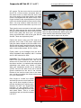
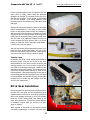
A view of the complete Yak 55SP 2.1m (83”) kit contents.
Star scheme Blue/White - Product
#742000

Building Instructions
General Tips:
We recommend that you follow the order of construction shown in this manual for the fuselage,
as it makes access to everything easier and saves time in the end. You can complete the assem-
bly of the wings and stabs at any point.
The first thing to do is protect the finished paint on the outside of the model from scratches and
dents during building - so cover your work table with a piece of soft carpet, cloth or bubble-plas-
tic. The best way to stop small spots of glue getting stuck to the outside painted surfaces is to
give the whole model 2 good coats of clear car wax first, but of course you must be sure to
remove this 100% properly before adding any additional paint, decals or trim. Alternatively you
can cover the majority of the fuselage with the bubble-plastic used to pack your model for ship-
ping, fixed with paper masking tape, which also protects it very well.
When sanding areas inside of the fuselage to prepare the surface for gluing something onto it,
do NOT sand right through the layer of glasscloth on the inside foam sandwich! It is only neces-
sary to rough up the surface, with 60/80 grit, and wipe off any dust with alcohol (or similar) before
gluing to make a perfect joint. It is very important to prepare the inside of the fuselage properly,
by roughing up and cleaning the surface, before gluing any parts to it.
Before starting construction it is a good idea to check inside the fuselage for any loose glass
fibres that could cut your hands, and a quick scuff over any of these with a coarse Scotchbrite
pad will remove them.
Landing Gear
The 1st job is to fit the landing gear legs and you
can leave these in place to protect the bottom of
the fuselage during the rest of the assembly.
The landing gear legs consist of 45° laminated
fibreglass and carbon cloth with a huge number of
carbon tows inside, all made in negative molds
and heat-cured. However it is still lightweight, and
is flexible enough to take the shock of any land-
ings that are less-than-perfect!
The plywood supports for the landing gear are
already factory-installed on top of the integral
exhaust tunnel. Please double-check now that this
is properly glued in. If you wish to reinforce it
against any really poor landings, you can add a
layer of heavy weight (8 oz/200 gram) fibreglass
cloth to join the vertical plywood supports to the
sides of the fuselage, laminated on with slow epoxy
- but this is absolutely not necessary for normal
landings.
Composite-ARF Yak 55 (2.1m/83”)
9

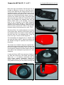
Both main legs are identical. Drill through the two
molded in dimples in the top of each leg, with a
sharp 5.5mm diameter bit. Using the M4 T-nuts to
check the position, drill four Ø 2mm holes around
each Ø 5.5 hole for the spikes of the T-nut to fit into.
Using one of the M4 bolts and a washer, pull the T-
nuts into the carbon legs a little, and secure them
with one small drop of thick CA. Trial fit both carbon
legs to the fuselage now, passing them thru’ the
factory milled slots in the fuselage, and bolting
them to the underside of the black fibreglass
exhaust tunnel using the M4 x 16mm bolts and
washers from inside the fuselage. When the align-
ment is correct, secure the T-nuts to the legs per-
manently using 30 minute epoxy on each T-nut.
Drill 4mm Ø thru’ the molded dimple in the bottom
of the carbon legs, and then fit the carbon legs into
the molded recess on the back of each wheel pant
and drill 4mm thru’ the wheelpant also, using the
hole in the leg to ensure correct alignment.
The wheelpants are designed for 4” wheels, and
we used the Dubro 400TL, which fit perfectly and
are durable enough for operation from hard sur-
faces also.
The wheels are installed using the supplied M4 x
45mm allen bolts as the axles, with the head of the
bolt on the outside of the wheel, and you will need
some spacers between the wheel and the plywood
inner plate of the wheelpant to give about 3 - 4mm
clearance.
If using the Dubro 400TL the sequence of parts on
the axle bolt should be: Bolt head, M4 washer,
wheel hub, 1 or 2 washers, wheelcollar, M4 nut
(with Loctite), washer, wheelpant, carbon leg,
washer and finally the M4 Locknut provided. If
using different wheels you may need to change the
Composite-ARF Yak 55 (2.1m/83”)
10

Composite-ARF Yak 55 (2.1m/83”)
number of washers and wheel collars required to give
the correct clearance between the wheel and the
wheelpant. For safety add a drop of Loctite to the lock-
nut on the inside of the carbon leg also.
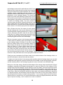
C-ARF can supply an optional tailwheel assembly for
this Yak 2.1m, or use any 25mm/1” Ø lightweight
wheel assembly from a hobby store. Shown here is
the Graupner 1” tailwheel assembly, available from C-
ARF as product #801002. You will need to use a sand-
ing block to create a small flat surface on the bottom
of the fuselage for the tailwheel bracket to sit on.
You do not need to make the tailwheel steerable
unless you fly from a hard runway - on grass a simple
fixed, or castoring action, is fine. A 3mm plywood plate
(15mm x 60mm) is already factory-installed in the bot-
tom of the fuselage in front of the fin post to secure the
tailwheel assembly to.
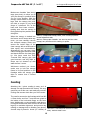
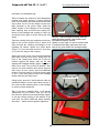
Cockpit Canopy
A painted moulded fibreglass canopy frame and clear
cockpit canopy are provided in the kit. Fitting the clear
canopy is quite simple, as the canopy is quite small
and rigid. Complete all the canopy frame fixings
before gluing in the clear canopy.
There are many methods of securing the canopy
frame to the fuselage. However we highly recommend
that you use the method shown here, using 4 plywood
tongues secured with M4 bolts and T-nuts, as it is rat-
tle-free, resistant to vibration and improves the tor-
sional stiffness of the fuselage - compared to using
hatch-catches etc.
Lightly sand (or scrape with the edge of a sharp knife)
the joint seams on both the fuselage and the canopy
frame that could prevent it sitting perfectly flush, and
check the fit to the fuselage. Tape the frame firmly in
position to the fuselage all around, and check align-
ment carefully.
Using a small flat file, make the 4 slots thru’ the flange
in the bottom flange of the canopy frame and the fuse-
lage flange. Each slot should be 3mm wide and 20 - 21 mm long. The outside edge of the slots
should only be 3 - 4mm inside the outer surface of the canopy frame. Position the slots about
50mm (2”) from the front and back of the canopy frame. Now remove the canopy frame, and
enlarge only the slots in the fuselage flange to 4.5mm width, 1.5mm extra towards the inside of
11
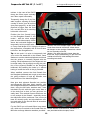
Any standard lightweight tailwheel
assembly will do. Notice also the tape
on the bottom of the rudder to prevent
the hinge wire sliding out in flight.
(above) 3mm thick ply blocks for rear
canopy fixings - secured with thick
microballoons mixture.
(below) Front blocks are 6mm thick,
tapered to match fuselage shape.

the fuselage to account for the thickness of the T-nuts.
Make up the 4 blocks that will be glued in the fuselage
using the milled 3mm plywood squares (20 x 20mm)
supplied, exactly underneath each slot a shown. It is
important that the inside surface of the blocks is per-
pendicular to the fuselage flanges. The back two
blocks only need a little sanding to achieve this, but for
the front two you will need to use double thickness ply-
wood squares, and sand the outer surface to an angle
to match the fuselage shape. The inner surface of
each ply square should be exactly flush with the outer
edge of each slot in the fuselage flange. Tack glue in
place with thick CA, and then secure afterwards with a
thick mixture of 30 minute epoxy and micro-balloons.
Drill a Ø 4mm hole thru’ the centre of each square,
and the fuselage side. Open up the Ø 4mm hole in the
4 milled plywood tongues provided (20 x 30mm) to Ø
5.5mm, and secure the M4 T-nuts into the holes with
a little thin CA. Carefully wax the area around the slots
on both the canopy frame and fuselage flange, in case
some epoxy gets on there in the next steps.
Bolt the 4 tongues in place in the fuselage with the M4
x 16mm bolts, so that they project up through the slots
in the fuselage flange as shown in the photo (right).
Refit the canopy frame onto the fuselage, taping it in
place exactly, so that the 4 tongues stick up thru’ the
slots you filed in it. Check canopy frame alignment
carefully and then glue the tongues in the frame using
just a little very thick 30 minute epoxy and micro-bal-
loons mixture. Be careful that the epoxy doesn’t seep
thru’ the slots and glue the frame to the fuselage ! When cured, remove the canopy frame and
reinforce all the joints with some more epoxy/micro-balloons mixture.
Finally you can counterbore the Ø 4mm holes in the outside surface of the fuselage a little, so
that the boltheads sit almost flush with the surface.
To make sure that the sides of the canopy match perfectly with the fuselage shape you can add
2 additional small plywood or phenolic sheet tabs in the middle of each canopy flange, as shown,
and file matching slots in the fuselage lip (phenolic strip is included in the hardware bag).
Now glue in the clear canopy. Sand the inside edges of the canopy frame carefully with 120 grit
sandpaper, especially the fibreglass joining tapes, to ensure a perfect fit of the canopy. Fit the
canopy frame onto the fuselage. Lay the canopy on top of the frame, view from the front to check
that it is centred and symettrically positioned, and then mark the approx. shape with a felt pen or
wax crayon. Trim the canopy approximately to size so that it is about 6 mm bigger than the edges
of the frame. When the canopy fits inside the frame, tape it into position temporarily, check that
it is aligned properly, and accurately mark the edge of the frame on the clear canopy. Remove
the canopy and trim exactly to shape, leaving about 6 - 7mm overlap outside the line all around.
Unless you are in a warm room, we recommend that the canopy is slightly warmed up with a hair
dryer to prevent cracking - but be careful not to melt or deform it!
Composite-ARF Yak 55 (2.1m/83”)
12

Composite-ARF Yak 55 (2.1m/83”)
Make some ‘handles’ from strong
tape (see photo) to allow you to
‘pull’ the canopy in position while
you fix it into position. With the
canopy frame bolted to the fuse-
lage, tack the canopy into posi-
tion with a couple of very small
drops of ‘odourless’ CA, at the
back and front lower corners -
making sure that the canopy is
firmly pulled up into position while
doing this.
When the canopy is tacked into
the frame, and it cannot twist any
more, you can carefully remove
the compete canopy frame and
secure the inside edge of the
clear canopy with a small bead of
slow epoxy and microballoons.
Alternatively you can use a spe-
cialist canopy glue that dries clear
and bonds well the the clear plas-
tic. We have used the ZAP
‘Formula 560’ canopy glue with
good success, and any drips or
drops can be cleaned up with
water before it cures.
Whichever method you chose,
make sure to bolt the canopy
frame in it’s final position on the
fuselage while the canopy glue
dries to ensure that it cannot
deform.
Cowling
Attaching the 1 piece cowling is easy, as it is
already cut and trimmed at the factory. We sug-
gest that you fit this now, and make any cutouts,
cooling and access slots after you fit the motor.
The cowl is secured to the fuselage with four M3
x 12mm bolts, and four T-nuts that are glued to
the inside of the horizontal flange on the fuse-
lage. Additionally you should add 2 small pheno-
lic tongues at the back lower corners of the fuse-
lage lip to maintain alignment, and prevent any
rubbing or damage due to vibration (see photo).
A small strip of phenolic sheet (15 x 40mm) is
13
(above) Completed canopy frame, also showing optional
central alignment tabs.
(below) Strong tape ‘handles’ are used to pull the clear
canopy into position whilst ‘tacking’ in place.
The cowl is secured with four M3 x 12mm
bolts, washers and T-nuts.

included in the hardware bag.
Sand or scrape any seams on the fuselage and
cowling that might prevent it sitting perfectly
flush. File notches in the back flange of the cowl-
ing to allow it to fit over the flange on the fuse-
lage (arrowed in the photo right). Sand the
inside surface of the flanges on the fuselage.
Now carefully wax all around the mating sur-
faces of the fuselage and cowling in case you
should get some glue on there during the next
steps.
Tape the cowling firmly into position on the fuse-
lage in the correct position. Drill 4 holes of Ø
3mm through the cowling and flanges of the
fuselage as shown. Space the holes about
25mm (1”) from the back and front, and 6mm
(1/4”) from the edge of the cowling.
Apply some wax or thin oil to the M3 bolts and
push them into the 3mm holes. Reach thru’ the
front of the cowling and screw the T-nuts into
position against the flange, with the flat
side
against the fibreglass flange. Apply one drop of
thick CA to each T-nut to hold in position, then
remove the cowl carefully and secure properly
with some 30 min. epoxy and micro-balloons
mixture. You can grind or cut off the lower edges
of the T-nuts that project below the fuselage
flange after the glue has cured.
Using epoxy, glue the 2 small phenolic tabs, as
mentioned above, at the lower back corners of
the cowl and file matching slots in the fuselage
to ensure correct alignment.
Tip: If you have a flexible drive, or 90 degree
attachment for your Dremel, then you can cut
the slots thru’ both the cowl and fuselage togeth-
er via the cooling opening in the bottom of the
cowl after you have made this when installing
the motor - which ensures perfect alignment.
Composite-ARF Yak 55 (2.1m/83”)
14
Notch
(above) T-nuts are fitted reversed, with the
spikes pointing inwards, and secured with
microballoons/epoxy mixture.
(below) Lower edge of cowl is secured with
2 small phenolic tabs, glued into the cowl,
that fit into slots filed in the fuselage flange.
2 phenolic tabs

Composite-ARF Yak 55 (2.1m/83”)
Horizontal Stabs
The stabs are 95% factory-finished
and the hinging is completed, using
4 large Robert hinge-points in each
elevator - so you only need to install
servos, horns and linkages. The
fibreglass tube inside the fuselage
that accepts the carbon stab spar,
and the holes for the anti-rotation
pins are also jig-installed at the fac-
tory, so the alignment and inci-
dences are already perfectly set. Please double-
check now that the 6mm fibreglass anti-rotation
pins are securely glued into the root ribs.
Insert the 14mm Ø carbon tube spar in the fuse-
lage sleeve, and slide on both stabs. Check the
fit between the root ribs and fuselage, and if nec-
essary you can sand the roots of the stabs
slightly for a perfect fit. The carbon tube may
need to be shortened a little to 275mm long.
Due to manufacturing tolerances it is possible
that the carbon tube may be a little tight, or loose
in the fibreglass tube in the fuselage. If it is a
slightly tight you can sand the outside of the car-
bon with 600 grit - and if it is a little loose you
can either spray a few coats of clear coat on it,
or even cover it in one layer of clear tape.
Servos: The elevators can travel more than 45
degrees, and if you are going to use the maxi-
mum throw for 3D manoeuvres, we strongly rec-
ommend hi-torque digital servos like
JR8411/8511/8611 or Futaba S9351. It is not
just that the torque of a standard servo is not
enough - it is also the play in the gears which
could cause problems centering, and it might
result in high speed flutter.
IMPORTANT - Servo Output arms:
To obtain large elevator throws of around 45°
you will need to use servo arms of 30mm (1.25”) length, and it is very important that these are
capable of handling the stresses placed on the splines by high-power digital servos, which can
strip the plastic splines out of low quality/soft plastic arms - resulting in flutter.
We highly recommend that you use full metal arms, but high-quality rigid reinforced plastic arms
(like the grey Dubro types shown here) can also be used with care.
The elevator servos are installed, inverted, in the plywood root rib as shown - with the servo out-
put shaft towards the leading edge of the stabs. The cutouts in the root ribs are milled for stan-
15
(above) Completed stab servo & linkage, also
showing the position of the M3 stab securing
bolt, recessed into the bottom of the stab.
Note positions of clevises on the horns for the
maximum mechanical advantage.
(below) You should use a 30mm long high-
quality reinforced plastic or metal servo arm
on powerful digital servos.

dard sized servos.
NB: Screw the servos into place with the Ø 2.9 x 13mm
screws provided in the kit - not the standard screws that
come with the servos.
The slots for the supplied phenolic elevator horns are
already partly milled in the elevators, but you will need mill
them deeper - to at least 13mm (1/2”) depth so that the phe-
nolic horn fits into the balsa block in the eleva-
tors right up to the small shoulders on the horn.
It is important that both horns are in identical
positions in relation to the hinge axis to give
equal elevator movements. It is also important
that the horns are directly in line with the servo
arm, so that there are are no twisting forces on
the phenolic arms. Depending on what type of
servos and arms you chose to install, you may
need to add thin plywood shims to the inside
surface of the root rib to position the servo
exactly in line with the elevator horns.
Do NOT use single-sided ball-links on the plas-
tic servo arms or phenolic control-surface horns
to obtain the correct alignment, because they
will twist the arms & cause flutter. This is a solid
experience and you should consider it a FACT.
Adjust the position of just one of the slots slight-
ly, forward or backward as necessary, so that the
clevise holes in the horn are exactly perpendicu-
lar to the hinge axis when the elevator is in the
neutral position. When horn fits fully into the slot,
put a layer of plastic parcel tape over the area of
the milled slot, wax it, and then cut through the
tape with a sharp knife to allow the horn to be
glued into the slot. This stops excess glue get-
ting on the surface of the elevator, and makes
the clean-up easy and quick! Rough up the glu-
ing surface of the horn, and glue it into the slot
with 30 minute epoxy and microballoons.
When the glue has fully cured on the first horn,
remove the tape, and make a horn alignment
template from thin plywood (see photo in wing
section) and a 1.6mm drill or piece of wire, and
use it to install the horn in the other elevator,
adjusting the slot position as needed. This
method ensures identical elevator throws.
Make up the elevator linkages from the 60mm
long M3 threaded rods, with 2 clevises and 2 x
Composite-ARF Yak 55 (2.1m/83”)
16
(above) Use waxed parcel tape to protect
the painted elevator surface while gluing in
the control horns.
(below) Adust the position of the servo or
the slots slightly if necessary to make sure that
the linkages are directly in line.

M3 nuts for each stab, as shown in the photos.
The clevise should be positioned in the servo
arm hole about 25mm from the servo centre,
and on the elevator horn it should be on the 4th
or 5th hole out from the elevator surface - to
maximise the mechanical advantage and reduce
any chance of flutter. With your transmitter
throws set at maximum (125%) this will still allow
even the hi-rate/3D throws mentioned at the end
of the manual.
‘Loctite’ the quick-link and lock-nut on at least
one end of all linkages. Add a couple of short
lengths of silicone tube over all clevises to pre-
vent them opening accidentally in flight.
Of course you will also need to cut out a corre-
sponding rectangular shape in fuselage for the
back of each servo as they will project into the
fuselage by about 20mm (3/4”). See photo right.
The stabs are secured to the carbon tube using
two M3 bolts, screwed thru’ the bottom surface
of the stabs, into T-nuts that you must glue
inside the carbon tube. There is a small plywood
reinforcing plate inside the stab that the bolts will
pass thru’, and the centre of this is 85mm from
the root.
Apply some masking tape to the bottom of the
stabs and mark the centreline of the stab tube
on it. Fit the carbon tube into one stab, and drill
a Ø 2.4mm hole 100mm out from the root of the
stab, thru’ the bottom surface, the ply reinforce-
ment, the fibreglass sleeve and the bottom of
the carbon tube. Tap the hole M3. Remove the
carbon tube and glue in the M3 T-nut, using a
thick mixture of 5 minute epoxy and micro-bal-
loons, with the M3 bolt temporarily in place to
ensure alignment. Wax or oil the bolt first !
You will need to grind or file the sides of the T-
nuts a little so that they will fit inside the carbon
tube.
Fit both stabs tightly to the fuselage, and then
drill the hole in the other stab and spar tube,
thread and glue in the T-nut as before. Counterbore the holes in the bottom surface of the stabs
for the boltheads so that they fit almost flush with the bottom surface of the stabs, and put a piece
of clear tape over the bolt-heads for flight.
Note: Try to always leave the stab tube fixed in one stab, and never remove that one bolt, as it
is tricky to find the right position for the stab tube again if it is removed from both stabs!
Composite-ARF Yak 55 (2.1m/83”)
17
(above) Make slots in the fuselage for the
back of the servos. You can glue the socket
on the end of the elevator extension lead
into the fuselage as shown here.
(below) Location of the hole in the underside
of the stabs for the spar securing bolts.
The stabs are secured onto the carbon tube
spar using M3 bolts, into cut-down M3 T-nuts
that are glued into the ends of the tube with
epoxy and micro-balloons.

Rudder
The rudder is hinged to the fin using the Ø 2mm wire (sup-
plied) which passes thru’ the 3 phenolic hinge posts that are
factory-installed and aligned. File a point on one end of the
wire, and a short 90° bend on the other end and push it
through the tube in the rudder from the bottom, capturing the
3 phenolic hinges on the way. Don’t forget to secure the bent
end of the wire with some strong tape for flight.
Trial fit the double-sided phenolic rudder horn in the slot that
is already milled in the base of the rudder, and mark the part
that will be glued in. Remove it, mask the parts that will be
exposed, and scuff the centre part on both sides with coarse
sandpaper. Cover the slot area on both sides of the rudder
with waxed plastic parcel tape, as mentioned in the
Stabiliser section above. Cut thru’ the tape to expose the
slots in the rudder. Glue in place with 30 min. or slow (not 5
minute !) epoxy and microballoons mix, making sure that it
is centred in the rudder. The front edge of the phenolic horn
should be flush against the back of the balsa false leading-
edge inside the rudder. Remove the plastic tape
from the rudder and horn when the glue is hard.
Servo: The rudder is a large surface on the Yak
which definitely needs a hi-torque power servo
of at least 12kg torque, and we recommend the
digital JR/Graupner 8511/8611/8811, or Futaba
S9351, for this very important control surface.
The servo is installed in a CNC milled compos-
ite mounting plate, which is then glued across
the fuselage just behind the back end of the
exhaust tunnel as shown here. Position the top
surface of the mounting plate 35mm (1.6”)
above the bottom of the fuselage, so that the
pull-pull wires pass underneath the rear fuse-
lage bulkhead. If you are using a larger and
heavier motor than the DA-50, you should install
the rudder servo mount as far back as possible
to help with setting the correct CG.
If using a full-length pipe, then you will need to
cut and extend the muffler tunnel, and the rud-
der servo mount will need to be raised by
approx. 80mm to clear it. In this case the position of the slots for the pull-pull cables to exit the
fuselage will change from the ones shown here.
To prepare the mount, glue the ply plate to the bottom of the balsa with CA and mount the servo
with the Ø 2.9 x 13mm screws provided, not the standard ones that come with the servo. The
composite balsa stiffening rails are glued into the milled slots under the front and back of the
plate with thin CA. Depending on the exact location of the servo mount you may need to sand
Composite-ARF Yak 55 (2.1m/83”)
18

the ends a bit for a perfect fit.
Rough up the fuselage sides before gluing the
complete assembly into place with 30 min.
epoxy, and then reinforce these important joints
with the glassfibre tape provided in the kit, and
24hr laminating epoxy (see photo).
Note: Fit the wings to the fuselage, and secure
with the M6 pl;astic nuts, before gluing in the
rudder servo mounting plate - so that you cannot
accidentally deform the fuselage.
Rough sand the top surface of a 25mm (1”) Ø
metal output disc, and the bottom of the pheno-
lic rudder servo arm. Centre the servo using
your R/C and glue the phenolic horn in place
perpendicular to the servo sides, using 30
minute epoxy. Then remove the assembly and
secure the phenolic arm to the disc with the 3
small M2 bolts and nuts (included), in a similar
manner as for the aileron servo arms.
Make up the pull-pull wires for the rudder from
the hardware supplied, with a loop at the front
that goes over the hooks on the output arms,
and a quick-link with turnbuckle and locknut at
the rudder end. We cross the wires over in the
fuselage, as then the exit slots are further back -
and almost hidden under the stabs. For security
pass the closed loop cable
through the supplied ‘crimping
tubes’ 2 times before squash-
ing flat with large pliers. Make
sure that the wires are tight,
and check and re-tension
them after the first few flights
as the cables straighten out.
Even a small amount of slop
will prevent your Yak from per-
fect tracking.
With servo mounted in the
position shown, and the cables
crossed, the centre of the slots
(30mm x 3mm) for the pull-pull
cable exits need to be approx.
125mm (5”) from the back of
the fin and 25mm (1”) above
the bottom of the fuselage.
Composite-ARF Yak 55 (2.1m/83”)
19
(above) Rudder servo mount positioned to
suit heavy engine at top end of power range.
Secure the plate to the fuselage sides with
the glassfibre tape supplied, and slow epoxy.
(Below) Pull-pull cable exit slots suit rudder
servo positioned as above.
125mm

Wings
The wings are 95% finished at the factory, and
have already been installed on your fuselage to
check alignment. They fit on a Ø 30 x 790mm
aluminium alloy spar tube, with 6mm Ø fibre-
glass rod anti-rotation pins at the front and back,
which are all completed for you. Each wing is
secured to the fuselage with a large M6 plastic
nut, that screws onto the factory-installed bolt in
the wing root. All you need to do is mount the
servos, glue in the aileron horns and make up
the linkages using the included hardware.
Please double-check now that the front and rear
anti-rotation pins, and the M6 nylon wing bolt,
are securely glued into the root ribs of the wings.
You can also check the inside structure of the
wings easily at this point, thru’ the cutouts in the
root ribs - to make sure that all critical compo-
nents are properly glued in position.
Mill the slots at least 13mm deep, and glue the
phenolic aileron horns into the milled slots in the
same way as the elevator horns, making sure
that the clevise holes are perpendicular to the
hinge axis, which is about 3mm behind the slot
in the bottom of the wing skin. As before, we
advise you to fit just one horn first, then make a
template (see photo right) to ensure that the
other horn is positioned the same. You can
make the template from card or thin ply, with a
1.6mm drill or piece of wire thru’ it to locate in the
upper hole of the horn.
Servo choice: We highly recommend using a
hi-torque digital servo (eg: JR/Graupner
8511/8611 or Futaba S9351) for each aileron as
the surfaces are very large. We also strongly
recommend that you secure the phenolic servo
arm extensions to metal output discs on the ser-
vos, and not plastic discs. (see also page 19)
The servo hatch openings are pre-cut in the
wing, and supplied with matching servo covers
and CNC milled plywood servo mounts. Sand
the inside surface of the hatch covers and the
milled ply parts that make up the servo mounts
to make sure you have a good gluing surface.
Assemble the servo mounts from the milled ply-
wood parts for each servo, using thin CA and a
Composite-ARF Yak 55 (2.1m/83”)
20
Page is loading ...
Page is loading ...
Page is loading ...
Page is loading ...
Page is loading ...
Page is loading ...
Page is loading ...
Page is loading ...
Page is loading ...
Page is loading ...
Page is loading ...
Page is loading ...
Page is loading ...
Page is loading ...
-
 1
1
-
 2
2
-
 3
3
-
 4
4
-
 5
5
-
 6
6
-
 7
7
-
 8
8
-
 9
9
-
 10
10
-
 11
11
-
 12
12
-
 13
13
-
 14
14
-
 15
15
-
 16
16
-
 17
17
-
 18
18
-
 19
19
-
 20
20
-
 21
21
-
 22
22
-
 23
23
-
 24
24
-
 25
25
-
 26
26
-
 27
27
-
 28
28
-
 29
29
-
 30
30
-
 31
31
-
 32
32
-
 33
33
-
 34
34


Carf-Models Yak 55SP Owner's manual
- Category
- Toys & accessories
- Type
- Owner's manual
- This manual is also suitable for
Ask a question and I''ll find the answer in the document
Finding information in a document is now easier with AI
Related papers
-
Carf-Models Composite-ARF INTEGRAL Owner's manual
-
-
-
-
-
-
-
-
-
Other documents
-
 Game Of Bricks UCS 7181 Light Kit for Star Wars TIE Interceptor User manual
-
Carl Goldberg Products GBGA1069 Owner's manual
-
 Phoenix Model Yak 54 User manual
-
 AJ Aircraft Laser 230z Assembly Instructions Manual
-
 Xyfx 30cc Geebee- R3 Assembly Manual
-
Sunnydaze Decor XLP-703 Installation guide
-
 Hangar 9 HAN2530 Owner's manual
-
Extreme Flight YAK-54 ARF User manual
-
-
Turnigy CriCri-70 Assembly Manual


