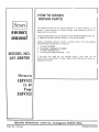
Craftsman 247298780 Owner's manual
- Category
- Mini tillers
- Type
- Owner's manual
This manual is also suitable for

I
CAUTION:
ReQd _FETY
RULESand
BNSTR_TaONS
c=refullv
CRRFT_MRN_
Am
ETiLL
,, AssembBy
O_rating
oMaintenance
,RepOt Par_s
ROEBLrC"K AND CO., Chl_U. (_0684 U_
PART NO. 770-7764 PRINTED IN US.A,

'rrr_'_:r_ -... ° ' ._-_'rrr_r_'_r_r___-_qr_rr_
FULL:ONE YEAR WARRANTY !
or one year from tile date (_f pur.chase, Sears will repair any defect i_ material or- ,,
orkmanship in this TILLER at no charge '
the TILLER is used for commercial or rental purposes, this warranty applies for only i
thirty days from [he date of purchase,
Warranty service is available by contacting the nearesi Sears store or Service Center i
throughout the United States.
This warranty gives you specific legal rights, and you may also have other rights _,
Which vary from state to state Sears, Roebuck and Co."
_. Sea_s Tower _,
I_ BSC-4.14:: ==
_. Chie,.,-i_l.d,,IL 60684

MPORTANT
It is suggested that this manual be read in its entirety before attempting to assemble or operate. Keep this
manual in a safe place for future reference and for ordering replacement parts.
This unit is shipped WITHOUT GASOLINE or OIL. After assembly, see operating section of thts manual
for proper fuel and amount.
Your tiller is a precision piece of power equipmei!.t, not a play thing. Therefore, exercise extreme caution
at all times.
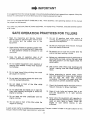
SAFE OPERATION PRACTICES FOR T LLERS
1, Read the Ope[ating and Service Ownerts
Manual carefully. Be thoroughly familiar with
the controls and the proper use of the
equipment.
2.. Never allow chltdren to operate a power tilter.
Only persons well acquainted with these rules
of safe operation shou}d be allowed to use
your til ler.i
tl.
12
13,
Do not fill gasoline tank while engine is
running. Spilling gasoline on hot engine may
cause a fire or explosion.
Do not run the engine while indoors. Exhaust
gases are deadly poisonous.
Be careful not to touch the muffler after the
engine has been rupning, tt is hot°
3, Keep the area of operation clear of all 14,
persons, particularly small children and pets,
4, Do not operate equipment when barefoot or
wearing open sandals_ Always wear substan-
tial footwear,
5. Do not wear loose fitting clothing that could
get caught on the tiller,
6, Do not start the engine unless the shift lever
is in the neutral iN) position,
7, Do n,ot stand tn fi'ont of the tiller while
starttng the :eilgtne.
!5_
16_
I 7,
8, Do not blac_ feet and ha.nd.S,o,n or..near thi_
tines _vhen st_arttng the engine' 5r white {he 18.
eng'lne is i'U_rilng,
9, Do not leave thetll"lar una{t.ended with the
e6gtne running, 19.
l& I)o not.walk :in front of the tiller wh{te the
engine is ru.nntng,
Before any maintenance work iS performed or
adjustments are made, remove the spark plug
wire and ground it on the engine block for
added safety,
Use caution when ti'lling near buildings arid
fences, rotating tines can cause damage oi'
injury.
Before attempting to remove rooks, bricks
and other objects from tines, stop the engine
and be sure the tines have stopped
completely. DisconneCt the spark plug wire
and ground to prevent accidenta! starting.
Check the fine and engine mouhttng bolts at
frequent Intervals for proper tightness.
Keep all nuts, bolts and screws tight to be
sure ,the equipment ts in safe working
condition,
Never store the equlpmetlt with gasoline in
the tank tnstde of a building where fumes may
reach an open flame or spark_ Allow the
engine to cool before storing tn any
enclosure,
A spark arrest muffler is available as an accessory part, "Thepart number is listed in the parts section Of this
mendel. Check muffler legal requirements in your area
3

INDEX
Warranty ................. 2
Safe Operat ion Practices ................ 3
Introduction .................. 4
Contents of Hardware Pack ............... 5
Tiller Identificat.ion ..................... 6
Assembly instructions ..................... 7
Engine Preparation ......................... 9
Adjustments .................................... 9
Controls. _.;...... :............ ,................. 9_
Operation ................................. 12
Tilling ................. 13
Titling Hlttts ......................... 13
Maintenance ................................. 13
Off-Season Storage ............... 17
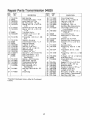
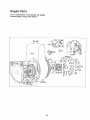
Transmisstor_,.- Repair Pads .... 20
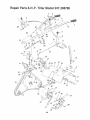
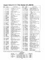
Tilter--Repair Parts .................... 22
Tiller Accessories .............. 25
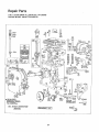
Engine--.Repair Parts .................... 26
How "fo Orde.r Repa!'r.Par_ts ...... Back Cover
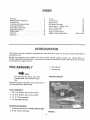
INTRODUCTION
This Product has been designed, engineered and manufactured to give you the best possible dependability
and performance.
Should you experience any problem you carinot easily remedy, please con'tact your nearest Sears, or
SimpsomSears Service Department° They have well qualified; competent trained technicians and the proper
tools to service Or repair this unit.
PRE...A.SSEMBLY
_ NOlrE
The right and left side of your tiller
is determined from operator's posi-
tion.
Before any step is undertaken, the instructions for
that step should be read through..
TOOLS REQUIRED:
to (2) 7116" Socket, open or bOx Wrench,
2. (1) 9116" Socket, open or box wrench..
3. (1) V4" Flat Screwdriver,
4. (t) AdjustableWrenoh,
MATERIALS REQUIRED:
1. Funnel (for-gas and olt,-_ NOTE: DO NOT MIX)
2. S..A_E.,-30 OtI_2% pints
3. Gas (regular)
4. Cleaning rag
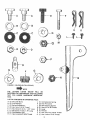
PARTS IN CARTON
FIGURE !,
4

G j
FIGURE 24{SHOWN IN FULL SCALE)
_NOTE
THE LETTERS LISTED BELOW
Gk
WILt, BE
REFERRED TO THROUGHOUT THE FOLLOWING
TEXT FOR EASIER HARDWARE IDENTIFtCA-
TION,
H
LiST OF CONTENTS IN HARDWARE PACK :
A (2) Shoulder Bolts J (!) Compression Spring
B (2) Fiat Washers K (2) Hair Pin Cotter
C(2) Bellevilte Washe, s L(2) Self Tapping Sorews
P (2) Hex Nuts 3/8-16 Thread M (t) Hex Nut 1/4-20Thread
E(!) Hex Screw 3f8_t6 x 1..50" Lo_g N (1) Lever
F (1) HexScrewl/4.20xl.75"Long O (1) Ferrule
G (3) Flat Washers 31B" P (1) Hex ,Jam Nut 318-24 Thread
H (1) Hex Locknuts3t8-24Thread Q (1) Hex Locknut 3/16 Thread
K
©

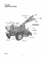
TBLLER
mDENTi:F6CAT ON
GearShill
Lover
011Di
Fuel Tank
Fuel Cap
.=-
Dum
Counterweight
Spsrk Plug
Wire
B_|t Cover
," ,die
Assembly
Tine:(,Enga_er_e.nt) Lever
iNQTE: Wheel (Engagempn_)
Lever on other sld_
*'_........... Depth Stake
Depth Stake
.... Adjustment Lever
Tine Shield
Flap
FIGURE 3,
S

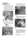
ASSEMBLY
INSTRUCTIONS
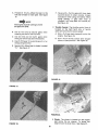
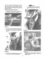
1. Handle Assembly
A. Place the handle assembty tn position on
the tiller so that tile holes in Ilandle line up
with holes in nqounting bracket..
B. Place flat washer (B) and belleviIte washer
(C) over shoulder on shou!der bolt (A)
Place sl]oufder bolt ai_d two Washers
thro, ugh handle mounting hot.es and
s'eq.Ure wH.h he× nut (D) from ihe inside of
handle. See !!guPe 4. :
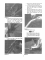
Dr "l!p. the tilte'r fOrwa?d, so it rests on
_o.unter_ejghl, $Iide d.ePth stake up
thrpughUl}er as s.ho,wn in, .figure 6, Pdll
rele&se #in On tiJier to loc_4 in place.
,+FJOURE6,
FIGURE 4.
C. Preassemble depth stake .to depth bar
assembly with hex sdrew (E), flat washer
(G) and hex locknut (Q)o See figure 5.
T_gl_tep nut an.d :boU, b_J.t d0. net over
tlOhtem ':P_,i.hsmu_t 'pivOt.
Flat W_Sh.er must go against s!:qt on
depth bai" assembly,
tr_ni_mlssion hodsiag: Slip depth:bar:over
bolt _,nd secu_te w.fth hair ptn :9otter (K).
See l.0.re,7:
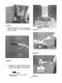
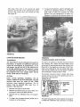
" 'I_::Ass..i_mB.ler_0tched edge:of gear shi-.ft lever
so n0(o.h faces forwa[d._:: P.!ac6gear shift
ie.vej" tl_rough slot th handle #An.el a.nd
66{t0._ h0.,leove_"we!d s{bd,-Secure:Wiih
: t=l_t w_,ller'(G)., oompre_s!e n .Sp(iog (J)i
andt.her fiat washer,(G) ahd: hex IOckhui
(H). See f!Ljbre'8.
G, Tighten hex tocknut until nut is Mush with
stud. See figure 8.

J_
K,
L.
Secure ferrule in gear shift lever (as shown
in figure 10) with hair p_n cotter (_),
To assemble the handle adjustment lever,
hook handle ad]ustmen.t' t:od '(already on
handle) into lever, Hoot_ to the outside.
See figure 11,.
Place handle adjustment tevet in place on
handle and secure with he× sci'ew (F) and
f0cl{nut (M), See figure 1t. Do not over
ttgilten handle adjustment lever must
pivot freely,
FIGURE 10.
F GU.REi1.
M., ThrOttl e Control [.ever,
NOTE -,
]_he throttle control may have four
holes in the lever bracket The holes
on the outside edge are to be used
for mounting on this unit., See figure
12.

Placethrottle controlleverup throughthehandle
panelandsecurewith twoselftappingscrews(L),
usinga t/4" flat screwdriver: See figure !3
FIGURE 13,
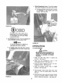
Engine ts shipped Wi{bout oil,
ENGINE
PREPARATION
1, Before starting. Fill crankcase with 23/4 pints
of SAE 30 heavy duty detergent oit or to full
mark on dipstick, Be sure that engine is !evet,
See figure 14, ..
2. Change 0(l._ter first 2 hours of operation and
every 25 hours the.re_ter, CheGk 0)_ eve_ 8
operati.ng h0grs, _ •
3Fill fuel tank with c_ean fresh regular grade of
gasoline, see figure 14
4 Open gas valve.
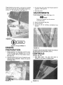
ADJUSTNgNTS
Handle Adjustment Lever. (See figure 15.)
NOTE
Figure 15 is viewed from the bottom
of handle panet.
A. Use if not enough free play;
B. Normal setting.
C. Use _f pin wi{t not withdraw c0mpletely from
bracl<et_ *
FIGURE .15.
To make the above adjustment !o0sen he x io_knut
a_nd'_e_os|!iOn the rod Ifi Hole A, B Or C,
CONTROLS
Location and Use.
1. Gear Shilt Lever: The gear shift lever is
located in the center of handle panel,
FIG FIGURE 16.
9

A. Forward (1 thru 5)--. Move the lever t.o the
left and forward for each gear, See figure
16,
_NOTE
The engine must be running tO move
the gear shift lever, ".....
B_
D.
E
Use (1) first and (2) second gears when
breaking the sod for the first time_
Use (3) third and (4! f0,urth gears when
till!ng soil which has been tilled before_
Use (5) fifth gear for pulverizing solt or for
transporting the tiller,
Neutra! ,(N)_Move lever to detent marked
"N," See figure 17.
F, Reverse (R)....Pull the gear shift lever back
(upward) slowly to obtain, reverse, Always
use caution when using the reverse_ When
u_tng {:everSe, .if gear' shift lever is
re}eased It'w[tl sqap. ba_k int_: neutral (N),
Se_'figure 18,
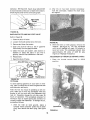
2Throttle Control: The throttle con'trol iever is
IQcated on the right' h_nd side of handle
panel arid _ontrels the engine speed,
A. St_op--Pull lever back (upWard) to stop the
engine, See fig0re 19,
B, Start_Push throttle oontrol lever forward
(down) to start position.. See figure 20,
FIGURE t7,
FIGURE 18.
FIGURE 19.
10
3. Ch0ke: The choke is located on the e.ng{qe
Jus.t .l_elow t'tle air cleaner. To choke the
engine move the lever down, See figure '21,

FIGURE 21.
4,, Handle Adjustment: The hand!e adjus{ment
release is located, on the right har_d handle
bar, See figure 22° FIGURE 23.
,::-:;.-
FIGURE 24.
FIGURE 22.
A. Squeeze up on handle adjustment lever
and place the handle in One Of nine (9)
positions See figures 23, 24, 25 and 26.
_NOTE
Figure 23 is viewed from the front of
tiller for clarity. FIGURE 25,
11

6, Wheel Engagement Lever; The wheel engage-
ment feverl_ lb(_ted on the right side of tilier_
A. T0 engage wheels hiov_, the lever out_vard,
To disengage or stop W!_eeis move lever
iriWard.. See figure 28, ,
RGURE 26.
WARNING
The gear shift lever must be in
Neutral (N),posltton befQre engaging
or. diseligag!ng tJte .tir_e ahd wheel
engagement levers. .....
5. Ttne :Engagement Levet: The ttne engagement
lever is located on the left side of tiller.
NOTE
It may :be necessary io slightly en-
gage gear shiftlever tb opemtb.
A. TO e_ngage tines move the lever outward.
To diseng&ge tlnes rdove (_ver Inward; See
ffgL_re 27,.
%
FIGURE 27,
12
FIGURE _8.
,
OPEBAT{O.N
TO START ENG|N E:
BE.SURE NQ ONE.IS STANDING IN
FR0NT oF THE TiLt=ER!.WHiLE .'THE
ENGINE: IL.SRUNNING", OR BEING
STARTED'.
1. Place t,he gear shift lever in neutrat (N)
position, See figure 17
2. Plaae the tine engagement lever in the
disengaged position. See figure 27_
3. Place the wheel er_gagement lever in the dis_
engaged .position, See figure 28.
P!ace the throttle control lever in FAST
position. See figure 20,
5_
,
Choke engine. Move choke tever down. See
figure 2t_ Once the engine starts, move the
lever up,
Stand atside of tiller, grasp the starter handle
and pul! out rapidly, Return it .slowly to the
engine_ Repeat as necessary. See figure 29,,

,'y :
FIGURE 29. ':'
TILL!NrG
1., Adj_is.{the depth stat<e bY pullJ.ng: the depth
stake atJjiJstment pin, Release the depth
30.
2, Lower the depth stake for transpdrtlng the
tiller,
3. Engage wheel engagement lever, select gear
on handle panel and ti!let will propel itself:
A, For tilling !n sod, raise the depth stalke so
the depth bar is one to two inches above
tt_e ti:nes.
Ti_is sett!ng {s _ised for breaking up the
sod .and shallow Cultivation. For further
depth ra}se theedepth stake and -make one
or two more passes over the area,
B_ For fitting loose and sandy soil, further
depth tn tilling can be achieved by raising
the depth stake to its higllest setting.
13
When tilling, if a hard spot or rock is
encountered, the tines may lift the
back Of the tiller out Of the ground
and start to walk across tlle ground,
To correct this problem raise up on
the handles,
TiLL:iNG:Hg NTS
Soil conditions a_e imp.ortaht for proper tilling.
The t!nes will not. readily penetrate dry, hard s0tl,
This may con.tribute to ex6essive bounce and
dill!out| handling of.the tiflei. Hard'soii should be
moistened prior to tilling,
ExtremelY Wet soi! wilt cause .soil 1o ball up or
clump,
When tilllhg in the Fall, all vines and long gt_ass
should be removedo This will preveht vibes from
wrapl_:lng around _he fine sh_ft Whlcl_ slows ttl!ing
operation,
The best method will be determined by the soil
condition, In some soils, the desired depth "is
obtained the first time over the garden, tn other
so.ils, the desired depth Is obtained by going over
the garclen two or three times_ In the latter' t_ase,
the depth stake should be raised (raising the
depth stake increases diggliqg depth) before each
suc.oeeding pass over the garden, and passes
st'io!jtd be made across the ierigth and width of the
garden alternately,. Rocks' which Are turned up
should be removed from thega¢dei_ area.
Handle Pressure: Eurther O0nt#ol of ttll!ng depth
and,t_:avet speed can be ol_tained by variation of
p_es_.ure on t_he handles.
When .using the depth stake e(downward pressure
onthe, handles Will increase the working depth
ahd 're.duce the' f0cwai'd_ speed. An upward
ptes.sti.r.e o,n tlie handleswill reduce the working
deistic:and tncrease the fo_ard speed, The type of
sotl arid wi_kt_qg conditioris Wilt determine the
actual se.t.t;!ng Ofthe;.deptl_ _J!ake,
tVlAINTENANCE
BELT RE,PLACEMENT:
_o not use a'n off:the-shelf belt.
If belt replacemer_t is required, ordei" belt or belts
by part number from your nearest Sears Service
Center.
Part No. 754-0220 Part No. 754-022t
5/8" x27" Short Belt 5/8" x52" Long Beh

Your tiller has been engineerea with the above
belts and Should not be replaced with an
off-the-shelf belt. The above belts are made of
special material (Kevtar Tensfl.e) for longer life and
better petformance.
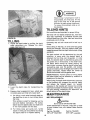
REMOVING AND REPLACING BELTS.
t. Remove belt cover; remove two bolts, two
nuts and four flat washers. See figure 31.
._ NOTE
Upon reassembly make sure the belt
is inside the guide ptn s. See .figure
34.
2, To remove th e front belt (short) pui! gear shift
lever back to reverse (R) position. S!]p the belt
off ehglne pulley towards the engine, See
figure 32.
Engine
\
FIIGURE 33._
FIGURE 32.
3_ Slip the belt off variable speed pu!|ey, remove
and replace with new bert. See figure 3.3,,
14
FIGURE 34,
4, To remove the rear. belt (long). Remove the
small belt first, follow steps t, 2 and 3 on
pages 14 and 15.

Move gear shift lever to the second (2) speed
position. Stip tl_e belt off the transmission pulley.
Pull the idler pulley down and remove the belle
See figure 35
5_ To clean foam element, wash in detergent and
sotution by squeezing similar to a sponge.
Wrap foam in cloth and squeeze dry. Coat
element with two tablespoons of engtne oil,
Squeeze to distribute and remove excess oil,
FIGURE 35,
CARE AND MAINTENANCE:
Transm|SsJon: :,
The transmt_,_lonts.pre-tubrtcated and sealed at
the factory, it requires no addfttona( lubrication
unless the"transmisslo8 t8 dtSassembte& To fitl
with grease, lay t#e left half of the transmfsston
on Its stde, add 28 Qunces of Pta.s{tlube #1 grease
and assemble the rtgh_ half to it. Thfs grease can
be purctfased from your nearest Sears Service
Center,. (Order Part NO. 737,-0133,)
AdrFitter:
Under normal operating conditions, the air
cleaner, .located on top of the earbUretor, must be
sei'viced ariel; everj ten hburs of use. Under
extremely dusty opeta.tirig:'b0tldit!ons, the air
eleanor tfiust be.,sei_i¢ed dfter eyery hour of
operatton, See fjlgtJre36.
t. Remove the _iing nut and cover.
2. Remove the S{_cend wing n,ut and metal disc
hotd[ng: the foam and paper element.
3. Remove t!_e {We elements from the support
b:ase.
4. To clean, tap the paper element (either top or
bottom) on a flat surface.
FIGURE 36.
CLEANING ENGINE AND TINE AREA
Any fuel or oil spilled on the tiller should be wiped
off promptly, Dirt,:'_eaves anct other debris must
not be left t_ accumulate around the cooling fins
(figure 37) or the eng[ne o.ron any part of the tiller.
C!ean t!le underside"'df: the tine shield after each
use, The dti't washes off the line easier if washed
off immediately instead of after it dries.
Tt_e blower housing is held in place with three
screws, One on the top of the engine and two on
the bottom:, See figure 37.
SPARK PLUG
15
Dirt
The spark plug gap shouid be cleaned and reset to
a &030-inch clearance every 25 hours of engine

operat!on.Seefigure38, Sparkplugreplacement
isrecommendedatthestar!of eachttlferseason;
checkengine,pal;tslistforcorrectplug'type,
2, After the elf has beendrained completely
from the crankcase,replacethe drain plug
andtighten.
FIGURE 38,
GASOLINE FILTER AND SHUT,OFF VALVE
Refer to figure 39
1_ Close the shut-offvaf.ve.
2., Loosen the thumb se.r._w be.tow the bowl,
3. Remove.ahd clean the scr_een;
4. Open the §hut-o!f valve to see if gasoline
ft_ws freely from the gas,91tne tank._
5, Qle_.n the bowl and,.scr.,eeh. Use alcohol or
acetone to c)ean ttie pa,lrts""ii you find a
gumf-ny, v'arnlsh-ltke sL{bstadce in the bowl,
6. Reassemble,
7 Qpet_ the sh'at-off valve.,
:Shut-Off'Valw
FIGURE 39.
Oil Change
To avoid spilling gasoline on your lawn or drive..
way, plan to change the oil when the gasoline tank
and carburetor are empty.
After the first two hours of operating a new en~
gine, drain the oil from the crankc_ase while the
engine is still hot and refill the.crankcase with
new oil; thereafter change the ott after ev&;r_,,25
tiours of operation., THis proc.edbre ensures for
minimum wear of engine parts and provides for
virtually trouble-flee opera'ti'Qn. To change the oil,
proceed as follows:
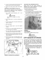
t. With the tiller on level ground, place a
suitable metal container under the oil drain
ptug, then remove the drain plug. See figure
40
tB
FiGUre40."
;& With the ti!ler on level ground, remove, the
clipsttck. See figure t4: Fill the cranf_case
uiqtil the oil reaches full mark, Fi.l! sl£wly to
avotd air locks: The crankqase should hold
apprO'kimate[y 2,_/4 pints of SAE"30 type
engine oi.L Replace thedipstick.
ADJUSTMENT OF THROTTLE CONTROL CABLE
1. Place the throttle cor_trol lever in STOP
position..
Screwdriver
FIGURE 41.

2 Loosen the casing clamp screw and move the
thro!fle control wire in as far as possible,
3. Tigl_ten the casing clamp screw See tlgure
41,
CARBURETOR ADJUSTMENT See figure 42,
Minor carburetor adjustment may be required to
compensate for differences in fuel, temperature,
altitude and load, To adjust:
1. Turn needle valve clockwise until it
closes.
_ CAUTION
Valve may be damaged by turning
1oo far._
just
2. Open needle valve 1.118 turns counterctock-.
wise,
3.. Close the idler valve in the same manner and
open 1-1 18 turns.
4. Start timeengine
5. Turn the needle valve in until the engine
misses.
6. Tl_en turn it out past smooth opetating point
until the engine runs unevenly.
7. Turn the needle valve mid-point between the
two Settings so the engine runs smoothly.
8. Set the throttle in the idle (slow) position and
set the Idle speed adjusting screw until a fast
idle is obtained,
9. With the throttle still in the idle position, turn
the idle valve tn and out until the engine idles
smoothly.
Idle Speed Adjusting Screw
Idle Valve
eedle Valve
FIGURE 42. CARBURETOR ADJUSTMENT
ADJUSTING THE CARBURETOR CHOKE
Proper choke and stop switch operation is
dependent upon proper adjustment of remote
contfols on the powered equipment.
TOcheck the Opi_ration o_the Choke:
1. Remove the air cleaner,
2. Push the throttle control all the way forward
to the START position, See figure 20. The
choke should be closed_ See figure 43,
3. T'he engine sllould shut of_ whBn the tt_rottle
control is all the way back (STOP position).
.'r
FIGURE 43.
TIRE PRESSURE
Tires should be Inflated from 8 to 15 p.s.i,
_CAUTION
Do not exceed 30 p.sJ,
OFF°SEASON STONAGE
tf the tiller is to be inoperative for a period longer
than 30 days, the following precautions are
recommended. Keep your tiller in a weatherproof
dry area. If stored for over 30 days the following
steps will protect the essential engine parts from
gum deposits.
1. Working outdoors, drain all fuel from the fuel
tank. Use a clean dry cloth to absorb the small
amount of fuel remaining in the tank, then run
the engine until all fuel in carburetor is
exhausted.
, ,
DO NOT DRAIN FUEl. WHILE
SMOKING, OR IF NEAR AN OPEN
FIRE.

2 Drain all the oit from tile crankcase(this
should be done after the engine has been
operatedand Is still warm) and refill the
crankcasewith clean new oft, See figure 40.
3. Disconnect the spark plug wire and remove
the spark plug from the cylinder'. Pour about
six drops of engine oil Into the cylinder, and
then pull the recoil starter several times to
spread the otl on the cylinder wal!, Replace
the spark plug, but DO NOT connect the wire.
4, Clean the engine and the entire tiller
thoroughly.
5. Wipe tines with oiled rag to prevent-rust,,
TtLLER INSTRUCTIONS FOR W1NTER
OPERATION (under 40°F,)
Engine Lubrication. Drain the sur_mer engine oil
while engine is warm. =Refitl.._wit[h new "winter
grade" oil, Run 'engine until wa'rmto_istribute the
new winter oi!..
Use oil "fdr sei'v:ice? 80, SD, dr SE, Use 5W-20 or
5W-30. 'If not available;, use. tOW; o.r t'0W,-30.
Fuel, Replace any summer gasoline-on hand or in
the fuel tank with fresh winter-grade gasoline. Use
lead*free or leaded "regular"' grade automotive
gasoline. Winter fuels have additives for faster
starting, Keep fuel tank full,,
NOTE
Many automotive gasolines rio long-
er contain "deqcer." A can of gas*
line de, icer fluid added to your gaso-
line supply wi_{ h_tp maintain the
engine's winter reliabll!ty,
Cold Starting Hints
1. Be sure to use proper winter-grade oil and
gasoline.
2. Declutch all possible external loads.
3, Set governor control at low-speed position.,
4. Turn carburetor needle valve approximately
1J8 turn counterclockwise, (Richer fuel
mixture) This will improve cold weather
starting and operatiol_,
18

19

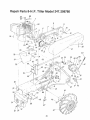
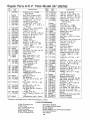
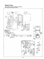
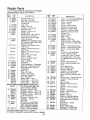
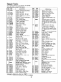
Repair Parts 8H=P. Tigter Mode! 247°2!t8780
!: ,{
3/
7
6
2O
Page is loading ...
Page is loading ...
Page is loading ...
Page is loading ...
Page is loading ...
Page is loading ...
Page is loading ...
Page is loading ...
Page is loading ...
Page is loading ...
Page is loading ...
Page is loading ...
-
 1
1
-
 2
2
-
 3
3
-
 4
4
-
 5
5
-
 6
6
-
 7
7
-
 8
8
-
 9
9
-
 10
10
-
 11
11
-
 12
12
-
 13
13
-
 14
14
-
 15
15
-
 16
16
-
 17
17
-
 18
18
-
 19
19
-
 20
20
-
 21
21
-
 22
22
-
 23
23
-
 24
24
-
 25
25
-
 26
26
-
 27
27
-
 28
28
-
 29
29
-
 30
30
-
 31
31
-
 32
32


Craftsman 247298780 Owner's manual
- Category
- Mini tillers
- Type
- Owner's manual
- This manual is also suitable for
Ask a question and I''ll find the answer in the document
Finding information in a document is now easier with AI
Related papers
-
Craftsman 247.298770 Owner's manual
-
-
-
-
Sears 917.299642 User manual
-
-
-
-
-
Other documents
-
 Jet Performance 62153 Installation guide
-
Bolens 247.29773 User manual
-
Cub Cadet 21AB455C710 User manual
-
-
-
-
White Outdoor RT65 User manual
-
MTD 450 Owner's manual
-
-
