Cumberland 24" and 36" Chimney Vent Owner's manual
- Type
- Owner's manual
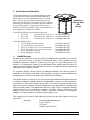
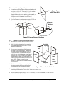
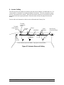
Cumberland 24" and 36" Chimney Vent is a natural ventilation accessory for mounting in the ceiling of animal confinement buildings or similar facilities. Air flow is adjustable by means of a movable baffle. The fully open position allows the entire vent area (see below) to provide vertical air flow from the inside to the outside of the building. An extension kit is available to provide an additional 4-foot of chamber length. To close the vent when not in use, a Winter Door accessory is available. Finally, for mounting the vent in the building roof, a Flashing kit is available.
Cumberland 24" and 36" Chimney Vent is a natural ventilation accessory for mounting in the ceiling of animal confinement buildings or similar facilities. Air flow is adjustable by means of a movable baffle. The fully open position allows the entire vent area (see below) to provide vertical air flow from the inside to the outside of the building. An extension kit is available to provide an additional 4-foot of chamber length. To close the vent when not in use, a Winter Door accessory is available. Finally, for mounting the vent in the building roof, a Flashing kit is available.


-
 1
1
-
 2
2
-
 3
3
-
 4
4
-
 5
5
-
 6
6
-
 7
7
-
 8
8
-
 9
9
-
 10
10
-
 11
11
-
 12
12


Cumberland 24" and 36" Chimney Vent Owner's manual
- Type
- Owner's manual
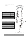
Cumberland 24" and 36" Chimney Vent is a natural ventilation accessory for mounting in the ceiling of animal confinement buildings or similar facilities. Air flow is adjustable by means of a movable baffle. The fully open position allows the entire vent area (see below) to provide vertical air flow from the inside to the outside of the building. An extension kit is available to provide an additional 4-foot of chamber length. To close the vent when not in use, a Winter Door accessory is available. Finally, for mounting the vent in the building roof, a Flashing kit is available.
Ask a question and I''ll find the answer in the document
Finding information in a document is now easier with AI