Liebherr XRCsd 5255 Prime Assembly And Installation Instructions
- Type
- Assembly And Installation Instructions

Installation Guide
Quality, Design and Innovation
home.liebherr.com/fridge-manuals

Contents
1 General safety instructions.................................. 2
2 Setup conditions................................................... 3
2.1 Space............................................................................. 3
2.2 Fitting the appliance into the kitchen unit.............. 3
2.3 Setting up multiple appliances.................................. 4
2.4 Electrical connection................................................... 5
3 Installation dimensions........................................ 5
4 Ventilation requirements...................................... 5
5 Transporting the appliance................................... 5
6 Unpacking the appliance...................................... 5
7 Mounting wall spacers.......................................... 5
8 Setting up the device............................................ 5
9 Setting up the appliance level.............................. 6
10 After setup............................................................ 6
11 Disposal of packaging........................................... 6
12 Explanatory symbols used.................................... 6
13 Reversing the door................................................ 7
13.1 Taking off the top soft stop mechanism.................. 8
13.2 Removing the bottom soft stop damper.................. 9
13.3 Disconnecting the cable connection........................ 10
13.4 Removing the top door................................................ 10
13.5 Removing the bottom door......................................... 11
13.6 Moving the upper bearing parts to the other side. 12
13.7 Moving the central bearing parts to the other
side................................................................................. 14
13.8 Moving the lower bearing parts to the other side.. 14
13.9 Moving the door bearing parts to the other side.... 15
13.10 Moving the handles to the other side*..................... 15
13.11 Fitting the bottom door............................................... 16
13.12 Fitting the top door...................................................... 17
13.13 Fitting the cable connection...................................... 17
13.14 Aligning the doors........................................................ 18
13.15 Fit the bottom soft stop mechanism........................ 18
13.16 Fitting the top soft stop mechanism........................ 19
14 Water connection*................................................ 19
15 Connect the water supply*................................... 20
16 Water tank............................................................. 21
16.1 Inserting the water tank............................................. 21
17 Water filter*.......................................................... 21
17.1 Installing the water filter............................................ 21
18 Connecting the appliance..................................... 21
The manufacturer is constantly working to improve all types
and models. Therefore, please be aware that we reserve the
right to make changes to the shape, equipment and tech‐
nology.
Symbol Explanation
Read instructions
Please read the information in these instruc‐
tions carefully to understand all of the benefits
of your new appliance.
Symbol Explanation
Full instructions on the internet
You can find detailed instructions on the
internet using the QR code on the front of
these instruction or by entering the service
number at home.liebherr.com/fridge-
manuals.
The service number can be found on the serial
tag:
Fig. Example illustration
Check appliance
Check all parts for transport damage. If you
have any complaints, please contact your
agent or customer service.
Differences
These instructions apply to a range of models,
so there may be differences. Sections that
apply to certain models only are indicated by
an asterisk (*).
Instructions and results
Instructions are marked with a .
Results are marked with a .
Videos
Videos about the appliances are available on
the YouTube channel of Liebherr-Hausgeräte.
1 General safety instructions
-Please keep this assembly manual in a safe
place so you can refer back to it at any
time.
-If you pass the appliance on, please hand
this assembly manual to the new owner.
-Read this assembly manual before installa‐
tion and use in order to use the appliance
safely and correctly. Follow the instruc‐
tions, safety instructions and warning
messages included at all times. They are
important for ensuring you can operate and
install the appliance safely and without any
problems.
-First read the general safety instructions in
the “General safety instructions” section of
the operating instructions, which accom‐
pany these installation instructions, and
follow them. If you cannot find the oper‐
ating instructions, you can download the
operating instructions from the internet by
entering the service number at
home.liebherr.com/fridge-manuals. The
General safety instructions
2 * Depending on model and options

service number can be found on the serial
tag:
-Observe the warning messages and other
detailed information in the other sections
when installing the appliance:
DANGER indicates a hazardous situation,
which if not avoided, will result in
death or serious injury.
WARNING indicates a hazardous situation,
which if not avoided, could result
in death or serious injury.
CAUTION indicates a hazardous situation,
which if not avoided, will result in
minor or moderate injury.
NOTICE indicates a hazardous situation,
which if not avoided, could result
in damage to property.
Note indicates useful advice and tips.
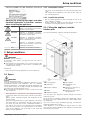
2 Setup conditions
WARNING
Risk of fire due to moisture!
If live parts or the power cord get wet, this can cause a
short circuit.
uThe appliance is designed for use in enclosed spaces. Do
not operate the appliance in open space or in damp areas
or where there is spray.
Normal use
-Only set up and use the appliance in enclosed spaces.
2.1 Space
WARNING
Leaking refrigerant and oil!
Fire. The refrigerant contained within the appliance is envi‐
ronmentally friendly, but flammable. The oil contained
within the appliance is flammable. Escaping refrigerant and
oil can ignite if they are of high enough concentration and
are exposed to an external heat source.
uDo not damage the pipelines of the coolant circuit and
the compressor.
-If the appliance is installed in a very damp environment
condensate water may form on the outside of the appli‐
ance.
Always make sure the installation area is well venti‐
lated. .
-The more refrigerant there is in the appliance, the larger
the space it is installed in must be. If the space is too
small, any leak may create a flammable mixture of gas
and air. For every 8 g size of the installation space must
be at least 1 m3. Specifications on the refrigerant in the
appliance can be found on the serial tag plate inside the
appliance.
2.1.1 Installation surface
-The floor of the installation site must be horizontal and
level.
-The height of the appliance base must be the same as
the surrounding floor.
2.1.2 Installation position
-Do not install the appliance in direct sunlight or next to
an oven, heater, or similar heat source.
-Always stand the appliance backed directly to the wall
using the enclosed wall spacers (see below).
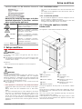
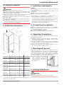
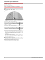
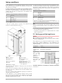
2.2 Fitting the appliance into the
kitchen unit
The appliance can be built into kitchen cabinets.
Fig. 1
(1) Top cupboard* (B) Door depth*
(2) Appliance* (C) Ventilation cross-
section*
(3) Kitchen cabinet* (D) Distance to the rear of
the appliance*
(4) Wall* (E) Distance to the side of
the appliance*
(A) Appliance depth*
Set up the appliance directly next to the kitchen cabinet
Fig. 1 (3).*
There must be a ventilation shaft at the depth Fig. 1 (D) of
the back of the top cupboard over the entire width of the
top cupboard.*
The cross section of the ventilation gap Fig. 1 (C) must be
maintained below the ceiling.*
If the appliance is installed with the hinges next to a wall
Fig. 1 (4), the distance between the appliance and the wall
must be at least 13 mm.*
Setup conditions
* Depending on model and options 3

If the appliance is installed with the hinges next to a wall
Fig. 1 (4), the distance between the appliance and the wall
must be at least 20 mm.*
In order to be able to fully open the door, the appliance must
protrude by the depth Fig. 1 (B) of the door from the front of
the kitchen cabinet. Regardless of the depth of the kitchen
cabinets Fig. 1 (3) and use of wall spaces, the appliance can
protrude further.*
A* B* C* D* E*
675 mmx75 mm Min.
300 cm2
Min.50 mm Min.13 mm
Appliances without handle / with recessed grip
A* B* C* D* E*
682 mmx82 mm Min.
300 cm2
Min.50 mm Min.20 mm
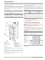
Appliances with recessed grip and glass/stone front
Fig. 2
(1) Top cabinet* (B) Door depth*
(2) Appliance* (C) Ventilation cross-
section*
(3) Kitchen cabinet* (D) Distance to the rear of
the appliance*
(4) Wall* (E) Distance to the side of
the appliance*
(A) Appliance depth*
Set up the appliance directly next to the kitchen cabinet
Fig. 2 (3).*
There must be a ventilation shaft at the depth Fig. 2 (D) of
the back of the top cupboard over the entire width of the
top cupboard.*
The cross section of the ventilation gap Fig. 2 (C) must be
maintained below the ceiling.*
If the appliance is installed with the hinges next to a wall
Fig. 2 (4), the distance between the appliance and the wall
must be at least 57 mm. This is how far the handle
protrudes when the door is open.*
In order to be able to fully open the door, the appliance must
protrude by the depth Fig. 2 (B) of the door from the front of
the kitchen cabinet. Regardless of the depth of the kitchen
cabinets Fig. 2 (3) and use of wall spaces, the appliance can
protrude further.*
A* B* C* D* E*
675 mmx75 mm Min.
300 cm2
Min.50 mm Min.57 mm
Appliances with lever handle
Note
A set for restricting the door opening angle to 90° can be
acquired from Customer Services for appliances with soft
closing.
Ensure that the following conditions are met:
-Recess dimensions are adhered to .
-Ventilation requirements are complied with (see 4 Venti‐
lation requirements) .
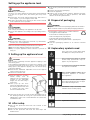
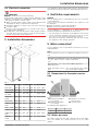
2.3 Setting up multiple appliances
NOTICE
Risk of damage caused by water condensate!
uDo not install this device directly beside another fridge/
freezer compartment.
These appliances are designed for different types of instal‐
lation. Only combine appliances if the appliances are
designed for this. The following table shows the installation
options by model:
Setup type Model
Single All models
Side-by-Side
(SBS)
Model that start with S....
Side-by-side
with a
distance of
70 mm
between appli‐
ances
Otherwise
condensation
will build up
between the
units.
All models without side wall heating
Fig. 3
Assemble appliances according to separate installation
instructions.
Setup conditions
4 * Depending on model and options

2.4 Electrical connection
WARNING
Danger of fire due to incorrect positioning!
If the power supply cable or plug touches the back of the
appliance, the vibration can damage the power supply cable
or the plug resulting in a short circuit.
uMake sure the power supply cable is not trapped under
the appliance when you position the appliance.
uInstall the appliance so that it does not touch any plugs
or power cables.
uDo not connect any appliances to sockets in the area of
the back of the appliance.
uDo not place and operate power strips/power distribu‐
tors and other electronic devices (such as halogen trans‐
formers) at the back of the appliances.
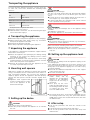
3 Installation dimensions
Fig. 4
ha b b` c c` d d`
CN.. 52.. 1855 597 675x719x609 654 1215x1222x
SCN.. 52.. 1855 597 675x719x609 654 1215x1222x
SBN.. 52.. 1855 597 675x719x609 654 1215x1222x
CN.. 57.. 2015 597 675x719x609 654 1215x1222x
CBN..
5753 / 576i
2015 597 675x719x609 654 1215x1222x
CBN.. 578i /
5783 / 579i
2015 597 675x— 609 — 1217x—
CBN.. 5773 2015 597 682x— 609 — 1217x—
CN.. 77.. 2015 747 675x719x759 804 1365x1372x
CBN.. 76.. 1855 747 675x719x759 804 1365x1372x
CBN.. 7753 2015 747 675x719x759 804 1365x1372x
CBN.. 778i 2015 747 675x— 759 — 1367x—
x For appliances with supplied wall spacers, the dimensions
must be increased by 15 mm .
4 Ventilation requirements
NOTICE
Risk of damage due to overheating in the case of insuffi‐
cient ventilation!
In the case of insufficient ventilation, the compressor can
be damaged.
uMake sure there is sufficient ventilation.
uObserve the ventilation requirements.
If the appliance is integrated in a fitted kitchen, the
following ventilation requirements must be met:
-The spacing fins on the back of the appliance are used to
ensure sufficient ventilation. These must not lie in cavi‐
ties or recesses in their final installation position.
-Basically, the larger the ventilation gap, the more energy
the appliance saves during operation.
5 Transporting the appliance
uOn initial setup: Transport the appliance in its packaging.
uWhen transporting after initial setup (e.g. relocation):
Transport the appliance unloaded.
uTransport the appliance upright.
uUse two people when transporting the appliance.
6 Unpacking the appliance
If the appliance is damaged check with the supplier immedi‐
ately before connecting it.
uCheck the appliance and packaging for damage during
transport. If you suspect any damage, please contact
your supplier immediately.
uRemove all materials that could prevent it from being
installed properly or prevent proper ventilation from the
back or the side panels of the appliance.
uRemove all protective films from the appliance. Do not
use sharp or pointed objects for this.
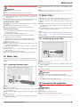
7 Mounting wall spacers
The spacers must be used in order to reach the declared
energy consumption levels as well as to avoid the formation
of condensate water at high levels of ambient humidity.
These will extend the depth of the appliance by approx.
15 mm. The appliance is fully functional if the spacers are
not used, but it will consume slightly more energy.
uIf wall spacers are supplied
with an appliance, these wall
spaces must be mounted on
the left and right of the back of
the appliance.
8 Setting up the device
CAUTION
Risk of personal injury!
uHave two people move this appliance into place.
Installation dimensions
* Depending on model and options 5

CAUTION
Risk of injury and damage!
The door can strike against the wall, which would damage
it. In the case of glass doors, the broken glass may cause
injury!
uProtect the door from striking against the wall. Place a
door stopper, e.g. a felt stopper, on the wall.
uA device that limits door opening to 90° can be ordered
from a qualified service provider.
WARNING
Unstable appliance!
Risk of injury and damage. The appliance can tip over.
uSecure the appliance according to the operating instruc‐
tions.
WARNING
Danger of fire and damage!
uDo not place devices that give off heat, e.g. microwaves,
toasters, etc. on the appliance.
Make sure that the following requirements are fulfilled:
qOnly move the appliance when it is not loaded.
qOnly set up the appliance when someone is present to
help you.
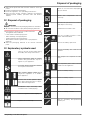
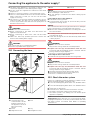
9 Setting up the appliance level
CAUTION
Risk of injury or damage from the appliance tipping or the
door falling open!
If the additional adjustable foot on the base support is not
correctly positioned on the floor, there is a risk of the door
falling open or the appliance tipping. This can lead to injury
or property damage.
uUnscrew the additional adjustable foot on the support
until it reaches the floor.
uThen turn it another 90°.
uAlign the appliance so that it
stands firmly and by
applying the accompanying
spanner to the adjustable
height feet (A) and using a
spirit level.
uThen prop up the door:
Lower the adjustable foot on
the bearing bracket (B) until
it contacts the floor, then
turn it an additional 90°.
uThen prop up the door: Screw out the adjustable foot on
the bearing bracket (B) using the open-ended wrench
SW10 until it comes into contact with the floor, then turn
an additional 90°.
10 After setup
uPull off the protective film from the outside of the
housing.
uPull off the protective film from the trim strips.
uPull off the protective film from the trim strips and
drawer fronts.
uPull off the protective film from the stainless steel rear
panel.
uRemove all transport packaging.
uClean the appliance .
uMake a note of type (model, number), appliance designa‐
tion, appliance/serial no., date of purchase, and dealer
address in the designated fields .
11 Disposal of packaging
WARNING
Danger of suffocation from packaging materials and films!
uDo not allow children to play with packaging materials.
The packaging is made from recyclable materials:
-Corrugated card/cardboard
-Parts made of foamed polystyrene
-Films and bags from polyethylene
-Packing bands from polypropylene
-Wood frame nailed together with a polyethylene
window*
uTake the packaging material to an official collection
point.
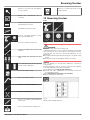
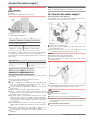
12 Explanatory symbols used
There is the risk of injury when doing
this! Obey the safety instructions!
These instructions apply to several
models. Only perform this step if it
applies to your appliance.
To install, please follow the detailed
description in the Guide.
This section applies either to a
single-door appliance or a double-
door appliance.
Choose one of the options: Appli‐
ance with right-hinged door or appli‐
ance with left-hinged door.
Installation step necessary with
IceMaker and/or InfinitySpring.
Loosen or tighten screws slightly.
Tighten the screws fully.
Setting up the appliance level
6 * Depending on model and options

Check to see if the next step applies
for your model.
Check the components are in
correctly.
Measure the specified measurement
and adjust if necessary.
Installation tool: Meter stick
Tool for assembly: Cordless screw‐
driver and attachments
Tool for assembly: Spirit level
Tool for assembly: Size 7 and size 10
spanner
Two people are required for this
step.
This step takes place at the selected
location of the appliance.
Aid for assembly: String
Aid for assembly: Square
Aid for assembly: Screwdriver
Aid for assembly: Scissors
Aid for assembly: Non-permanent
marker pen
Accessory kit: Remove components
Dispose of components that are no
longer needed.
13 Reversing the door
Tools
Fig. 5
WARNING
Danger of injury due to door falling out!
If the bearing parts are not screwed on tightly enough, the
door may fall out. This can result in serious injuries. In addi‐
tion, the door may not close causing the appliance to cool
improperly.
uScrew the bearing brackets/bearing pins on tightly using
4 Nm .
uCheck all screws and retighten them if necessary.
NOTICE
Risk of damage to side-by-side appliances caused by
condensate!
Certain appliances can be set up as side-by-side combina‐
tions (two appliances beside one another).
If your appliance is a side-by-side appliance:
uInstall the SBS combination in accordance with the
accompanying sheet.
If the configuration of appliances is specified:
uDo not change the door stop.
Fig. 6
Observe the reading direction.
Reversing the door
* Depending on model and options 7

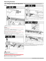
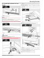
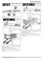
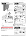
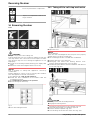
13.1 Taking off the top soft stop mecha‐
nism
Fig. 7
uOpen the top door.
NOTICE
Risk of damage!
If the door seal is damaged the door may not close properly
and the level of cooling is insufficient.
uDo not damage the door seal with the screwdriver!
uRemove the outer cover. Fig. 7 (1)
uDisengage and release the bearing bracket cover.
Remove the bearing bracket cover. Fig. 7 (2)
uUnlatch the panel with a slotted screwdriver and swivel it
to one side. Fig. 7 (3)
Fig. 8
CAUTION
Crushing hazard from the folding bracket!
uEngage the locking device.
uEngage the locking device in the opening. Fig. 8 (1)
uUnscrew the bolt with a screwdriver. Fig. 8 (2)
uRemove the bolt upwards. Fig. 8 (3)
uTurn the hinge in the direction of the door. Fig. 8 (4)
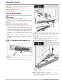
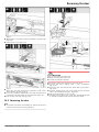
Fig. 9
uUnlatch the cover with a slotted screwdriver and lift it up.
Fig. 9 (1)
uTake out the cover. Fig. 9 (2)
Fig. 10
uLoosen the soft stop unit screw with a T15 screwdriver
approx. 14 mm. Fig. 10 (1)
uInsert a screwdriver behind the soft stop mechanism on
the handle side and rotate the unit forwards. Fig. 10 (2)
uPull out the soft stop unit. Fig. 10 (3)
Reversing the door
8 * Depending on model and options

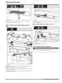
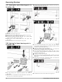
13.2 Removing the bottom soft stop
damper
Fig. 11
uOpen the bottom door.
NOTICE
Risk of damage!
If the door seal is damaged the door may not close properly
and the level of cooling is insufficient.
uDo not damage the door seal with the screwdriver!
uUnlatch the panel with a slotted screwdriver and swivel it
to one side Fig. 11 ().
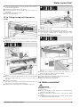
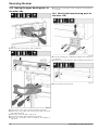
Fig. 12
CAUTION
Crushing hazard from the folding bracket!
uEngage the locking device.
uEngage the locking device in the opening Fig. 12 ().
Fig. 13
uRemove the bearing bracket cover and push it along the
hinge. Fig. 13 (1)
uLift the bolt with a finger or screwdriver from below.
Fig. 13 (2)
uInsert the screwdriver under the bolt head and remove it.
Fig. 13 (3)
Fig. 14
uTurn the hinge in the direction of the door. Fig. 14 (1)
uRemove the bearing bracket cover. Fig. 14 (2)
Fig. 15
uUndo the soft stop unit screw with a T15 screwdriver
approx. 14 mm. Fig. 15 (1)
uInsert the screwdriver on the handle side behind the soft
stop unit. Turn the unit forward. Fig. 15 (2)
uPull out the unit. Fig. 15 (3)
uPlace the soft stop mechanism to one side.
Reversing the door
* Depending on model and options 9

Fig. 16 *
uLoosen the screws with a T15 screwdriver. Fig. 16 (1)*
uPull out the adapter. Fig. 16 (2)*
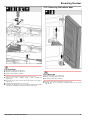
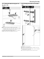
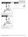
13.3 Disconnecting the cable connec‐
tion
Fig. 17
uLoosen the control panel of the appliance carefully to the
front. Fig. 17 (1)
uTurn the control panel up by 180°. Fig. 17 (2)
uPress the latching lug backward and pull out the plug
carefully. Fig. 17 (3)
uCarefully remove the cable over the bearing bracket from
the guide. Fig. 17 (4)
Fig. 18
uCarefully remove the gray cable from the guide in the
door. Fig. 18 (1)
uPress the lug behind the plug backward. Fig. 18 (2)
uCarefully pull out the plug upward. Fig. 18 (3)
Fig. 19
uLift up the cover with the slotted screwdriver and pull it
out. Fig. 19 (1)
uPull out the cable. Fig. 19 (2)
13.4 Removing the top door
Note
uTo prevent food items from falling out, take all food out of
the door racks before removing the door.
Reversing the door
10 * Depending on model and options

Fig. 20
CAUTION
Risk of injury if the door tips out!
uKeep a steady grip on the door.
uSet the door down carefully.
uCarefully remove the protective cover. Fig. 20 (1)
uLoosen the bolts slightly with a T15 screwdriver.
Fig. 20 (2)
uHold the door and remove the bolts with your fingers.
Fig. 20 (3)
uLift the door and place it to one side.
uCarefully lift the plugs out of the door bearing bush with
a slotted screwdriver and remove them. Fig. 20 (4)
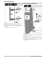
13.5 Removing the bottom door
Fig. 21 *
CAUTION
Risk of injury if the door tips out!
uKeep a steady grip on the door.
uSet the door down carefully.
uPull out the bolts toward the top. Fig. 21 (1)*
uSwing the door out, pull it upward and set it aside.
Fig. 21 (2)*
Reversing the door
* Depending on model and options 11

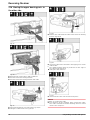
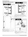
13.6 Moving the upper bearing parts to
the other side
Fig. 22
Fig. 23
uRemove both screws with a T20 screwdriver.
uLift and remove the bearing bracket.
uLift and remove the bearing bracket and cable.
Fig. 24
uPull the bearing bush out of the guide. Fig. 24 (1)
uSwing the cable holder out. Fig. 24 (2)
Fig. 25
uRemove the cable with the cable holder from the bearing
bracket. Fig. 25 (3)
Fig. 26
uInsert the cable mirror-inverted in the upper groove of the
cable holder.
wThe middle marking must be positioned on the edge of
the cable holder Fig. 26 (1).
uSwing the cable holder in.
Fig. 27
uInsert from the other side and latch into place.
NOTICE
Danger of crushing the cable
uPay attention to the markings when routing the cable.
The cable end with the double marking must be routed
into the door end piece.
Reversing the door
12 * Depending on model and options

Fig. 28
After making the change, the cable routing must look as
shown in the illustration.
Fig. 29
uTake off the cover to the front from above. Fig. 29 (1)
uRotate the cover 180° and clip onto the other side from
the right. Fig. 29 (2)
uLatch the cover into place. Fig. 29 (3)
uPosition the upper bearing bracket. Fig. 29 (4)
uInsert the screw with a T20 screwdriver and tighten it.
Fig. 29 (5)
uInsert the screw with a T20 screwdriver and tighten it.
Fig. 29 (6)
Fig. 30
uTake off the cover to the front from above. Fig. 30 (1)
uRotate the cover 180° and clip onto the other side from
the right. Fig. 30 (2)
uLatch the cover into place. Fig. 30 (3)
uPosition the upper bearing bracket. Fig. 30 (4)
uInsert the screw with a T20 screwdriver and tighten it.
Fig. 30 (5)
uInsert the screw with a T20 screwdriver and tighten it.
Fig. 30 (6)
Reversing the door
* Depending on model and options 13

13.7 Moving the central bearing parts to
the other side
Fig. 31
uRemove the washer. Fig. 31 (1)
uRemove the screws with the T20 screwdriver. Fig. 31 (2)
uRemove the cover carefully. Fig. 31 (3)
uScrew the bearing bracket and the film rotated 180°
firmly onto the other side. Fig. 31 (4)
uAttach the cover rotated 180° onto the other side.
Fig. 31 (5)
uPush the washer in from the front. Fig. 31 (6)
13.8 Moving the lower bearing parts to
the other side
Fig. 32
uLift the bearing pin completely upward and remove it.
Fig. 32 (1)
uRemove the screw with the T20 screwdriver and take off
the soft close connection. Fig. 32 (2)
uRemove the screws with the T20 screwdriver and take off
the bearing bracket. Fig. 32 (3)
Fig. 33
uTake off the cover. Fig. 33 (1)
Fig. 34
uPlace the bearing bracket on the other side and screw it
in using the T20 screwdriver. Start with screw 2 at the
bottom in the middle. Fig. 34 (2)
uScrew in screws 3 and 4. Fig. 34 (3,4)
uInsert the bearing pin completely. Make sure that the
latching lug is pointing to the rear. Fig. 34 (5)
uPlace the bearing bracket on the other side and screw it
in using the T20 screwdriver. Start with screw 2 at the
bottom in the middle. (2)
uScrew in screws 3 and 4. (3,4)
uRotate the soft stop connection 180°. Screw it on to the
other side of the bearing bracket with a T20 screw‐
driver. (5)
uInsert the bearing pin completely. Make sure that the
latching lug is pointing to the rear. (6)
Fig. 35
uPut back the cover on the other side. Fig. 35 (1)
Reversing the door
14 * Depending on model and options

13.9 Moving the door bearing parts to
the other side
Top door
Fig. 36
uUnderside of door faces upwards: Turn the door.
uPull out the guide bush: Press the lug with a slotted
screwdriver and, at the same time, insert the slotted
screwdriver under the guide bush. Fig. 36 (1, 2)
uSlide the guide bush included in the scope of supply to
the other side of the housing. Fig. 36 (3)
uUpper side of door faces upwards: Turn the door.
13.10 Moving the handles to the other
side*
Fig. 37
uPull off the cover. Fig. 37 (1)
uRemove the screws with the T15 screwdriver. Fig. 37 (2)
uRemove the handle. Fig. 37 (3)
uCarefully lift up the side plugs with a slotted screwdriver
and pull them out. Fig. 37 (4)
uInsert the plugs again on the other side. Fig. 37 (5)
Reversing the door
* Depending on model and options 15

Fig. 38
uPosition the handle on the opposite side. Fig. 38 (1)
wThe screw holes must be exactly above each other.
uTighten the screws using the T15 screwdriver. Fig. 38 (2)
uPosition the covers on the side and push them on.
Fig. 38 (3)
wEnsure that they latch into place correctly.
13.11 Fitting the bottom door
Fig. 39
uCarefully lift up the plugs with a slotted screwdriver and
pull them out. Fig. 39 (1)
uPosition the door from above onto the lower bearing pins.
Fig. 39 (2)
uInsert the center bearing pin through the center bearing
bracket into the bottom door. Make sure that the latching
lug is pointing to the rear. Fig. 39 (3)
uInsert the plugs again on the other side of the door.
Fig. 39 (4)
Reversing the door
16 * Depending on model and options

13.12 Fitting the top door
Fig. 40
uPlace the upper door on the center bearing pins Fig. 40 (1)
uAlign the top of the door with opening in the bearing
bracket. Fig. 40 (2)
uInsert the bolt and tighten with a T15 screwdriver.
Fig. 40 (3)
uFit the protective cover to protect the door: Insert the
protective cover and check that it lies flush on the door.
If not, insert the bolt fully. Fig. 40 (4)
NOTICE
Cable crushing
uThe marking on the cable must be centered in the holder.
The lug with the longer opening must point forwards.
uInsert the cover and press it down until it latches into
place. Fig. 40 (5)
uInsert the plugs. Fig. 40 (6)
13.13 Fitting the cable connection
Fig. 41
uTake out the control panel carefully. Fig. 41 (1)
uTurn the panel upward through 180°. Fig. 41 (2)
uEngage the plug on the control panel. Fig. 41 (3)
uLatch the control panel into the appliance again.
Fig. 41 (4)
uCarefully position the gray cable in the guide above the
top bearing bracket. Fig. 41 (5)
Reversing the door
* Depending on model and options 17

Fig. 42
uInsert the gray cable into the guide in the top door.
Fig. 42 (1)
uPress the latching lug backward Fig. 42 (2)
uEngage the plug. Fig. 42 (3)
uPosition the remaining cable length as a loop in the
guide, if required.
13.14 Aligning the doors
WARNING
Danger of injury due to door falling out!
If the bearing parts are not screwed on tightly enough, the
door may fall out. This can result in serious injuries. In addi‐
tion, the door may not close causing the appliance to cool
improperly.
uScrew the bearing brackets on tightly using 4 Nm .
uCheck all screws and retighten them if necessary.
uAlign the doors flush with the appliance housing using
the two slots in the lower bearing bracket and center
bearing bracket if needed. To do this undo the middle
screw in the bottom bearing bracket with the T20 tool
supplied. Undo the remaining screws a little with the T20
tool or with a T20 screwdriver and align via the slots.
Undo the screws in the middle bearing bracket with the
T20 tool and align the middle bearing bracket via the
slots.
uProp up the door: Screw out the adjustable foot on the
bearing bracket using the open-ended wrench SW10 until
it comes into contact with the floor, then turn an addi‐
tional 90°.
13.15 Fit the bottom soft stop mecha‐
nism
Fig. 43 *
uInsert the adapter on the handle side in the recess.
Fig. 43 (1)*
uTighten the screws using the T15 screwdriver. Fig. 43 (2)*
Fig. 44
uSlide the soft stop mechanism on the bearing bracket
side at an angle into the recess as far as it will go.
Fig. 44 (1)
uSlide the soft stop mechanism fully into the recess.
Fig. 44 (2)
wThe unit is positioned correctly when the rib on the soft
stop mechanism is in the guide.
uTighten the screw using a T15 screwdriver. Fig. 44 (3)
uPush the cover over the hinge. Fig. 44 (4)
Fig. 45
The door is open 90°.
uTurn the hinge in the mount. Fig. 45 (1)
uInsert the bolt with a T15 screwdriver in the mount and
hinge. Make sure that the latching lug is sitting correctly
in the groove. Fig. 45 (2)
Reversing the door
18 * Depending on model and options

uPush the bearing bracket cover along the hinge and fit it
on the mount. Fig. 45 (3)
uRemove the locking device. Fig. 45 (4)
uPosition the panel on the handle side and swing it in.
Fig. 45 (5)
wThe panel is clicked into place.
uClose the bottom door.
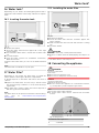
13.16 Fitting the top soft stop mecha‐
nism
Fig. 46 *
uInsert the adapter on the handle side in the recess.
Fig. 46 (1)*
uTighten the screws using the T15 screwdriver. Fig. 46 (2)*
Fig. 47
uSlide the soft stop mechanism on the bearing bracket
side at an angle into the recess as far as it will go.
Fig. 47 (1)
uSlide the unit in fully.
wThe unit is positioned correctly when the rib on the soft
stop unit is in the guide on the housing.
uTighten the screw using a T15 screwdriver. Fig. 47 (2)
Fig. 48
The door is open 90°.
uTurn the hinge in the bearing bracket. Fig. 48 (1)
uInsert the bolt in the bearing bracket and hinge. Make
sure that the latching lug is sitting correctly in the
groove. Fig. 48 (2)
uRemove the locking device. Fig. 48 (3)
Fig. 49
uPosition the bearing bracket cover and engage it. If
necessary push it apart carefully. Fig. 49 (1)
uPlace on the panel. Fig. 49 (2)
uSwing in the panel and latch it into place. Fig. 49 (3)
uSlide on the outer cover. Fig. 49 (4)
uClose the upper door. Fig. 49 (5)
14 Water connection*
WARNING
Electricity and water!
Electric shock
uBefore connecting to the water hose: Disconnect the
appliance from the mains.
uBefore connecting to water lines: Shut off the water
supply.
uThe drinking water connection may only be carried out by
a qualified gas and water installer.
Water connection*
* Depending on model and options 19

WARNING
Contaminated water!
Poisoning.
uConnect to potable water supply only.
Fig. 50 *
For 600 mm wide appliances:*
a* b* c* M*
~ 1150 mm ~ 1000 mm ~ 150 mm Solenoid valve
For 750 mm wide appliances:*
a* b* c* M*
~ 1075 mm ~ 925 mm ~ 150 mm Solenoid valve
The appliance’s water connection and inlet solenoid valve
are suitable for a water pressure of up to 1 MPa (10 bar).
Specifications for proper operation (flow rate, ice cube size,
noise level):
Water pressure:
bar MPa
1.5 to 6.2 0.15 to 0.62
Water pressure if using the water filter:*
bar* MPa*
2.8 to 6.2 0.28 to 0.62
If the pressure exceeds 0.62 MPa (6.2 bar): Connect a pres‐
sure reducer.
Make sure that the following conditions are met:
qThe water pressure is correct.
qWater is supplied to the appliance via a cold water pipe
that can withstand the operating pressure and is
connected to the drinking water supply.
qYou are using the supplied hose. Old hoses have been
disposed of.*
qThe hose fitting contains a filter with a gasket.*
qThere is a water valve between the hose pipe and the
domestic water connection in order to be able to cut off
the water supply if necessary.*
qThe water valve is located away from the back of the
appliance and is easily accessible so that the appliance
can be pushed far back as possible and the water valve
can be quickly closed if required. The correct clearances
are maintained.
qAll equipment and devices used for the water supply
comply with the applicable regulations in the country of
use.
qThe back of the appliance is accessible so that you can
connect the appliance to the drinking water supply.
qDo not damage or kink the hose when setting up the
appliance.
Note
Hoses of different lengths are available as accessories.*
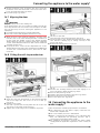
15 Connect the water supply*
Connect the hose to the appliance
The solenoid valve is located at the bottom of the back of
the appliance. Its connecting thread is R3/4.
Fig. 51 *
uRemove the cover Fig. 51 (2).
uEasy to fit: Lay the straight hose end Fig. 51 (7) on the
floor towards the left.
uPush the nut Fig. 51 (4) over the angled hose end
Fig. 51 (3) to the end and hold it in this position.
NOTICE
Damaged threads of the solenoid valve!
Solenoid valve leaks: Water can leak out.
uCarefully attach the nut Fig. 52 (1) and screw straight
onto the thread.
Fig. 52
uCarefully attach the nut Fig. 52 (1) and use both fingers to
screw straight onto the thread so it sits firmly.
WARNING
Broken auxiliary tool Fig. 51 (5)!
Cuts.
uUse the tool Fig. 51 (5) only at room temperature.
uTighten the nut Fig. 52 (1) with an auxiliary tool Fig. 51 (5)
to the maximum torque and until the tool Fig. 51 (5) is
overtorqued.
Connect the hose to the stopcock
uScrew the nut Fig. 51 (7) onto the stopcock Fig. 51 (8).
Connect the water supply*
20 * Depending on model and options
Page is loading ...
Page is loading ...
Page is loading ...
Page is loading ...
Page is loading ...
Page is loading ...
Page is loading ...
Page is loading ...
Page is loading ...
Page is loading ...
Page is loading ...
Page is loading ...
Page is loading ...
Page is loading ...
Page is loading ...
Page is loading ...
Page is loading ...
Page is loading ...
Page is loading ...
Page is loading ...
Page is loading ...
Page is loading ...
-
 1
1
-
 2
2
-
 3
3
-
 4
4
-
 5
5
-
 6
6
-
 7
7
-
 8
8
-
 9
9
-
 10
10
-
 11
11
-
 12
12
-
 13
13
-
 14
14
-
 15
15
-
 16
16
-
 17
17
-
 18
18
-
 19
19
-
 20
20
-
 21
21
-
 22
22
-
 23
23
-
 24
24
-
 25
25
-
 26
26
-
 27
27
-
 28
28
-
 29
29
-
 30
30
-
 31
31
-
 32
32
-
 33
33
-
 34
34
-
 35
35
-
 36
36
-
 37
37
-
 38
38
-
 39
39
-
 40
40
-
 41
41
-
 42
42


Liebherr XRCsd 5255 Prime Assembly And Installation Instructions
- Type
- Assembly And Installation Instructions
Ask a question and I''ll find the answer in the document
Finding information in a document is now easier with AI
Related papers
-
Liebherr XRFsd 5265 Prime Assembly And Installation Instructions
-
-
-
-
-
-
-
-
-
