Page is loading ...

Public Address System
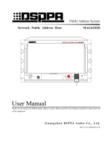
Public Address Multimedia Matrix
M2189
COMPACT DISC DRIVER
POWER
EMC MIC
Public Address Multimedia Matrix
OFF ON
M2189
TOUCH PAD
FULL ALARMING
USB
User's Guide
Welcome to use our public address system. Please read this manual carefully before using this device for your
better use.
LY I nt e r n a t i o n a l E l e c t ro n i c s C o . , L t d .
http://www.lyintlcorp.com

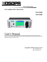
About this Manual
This Manual is used since the date when the development of Intelligent Broadcast Center System
is completed. The manual contains the system introduction, precautions, system connection
instruction, product use instruction, product specification and so on. Please read this manual
carefully before installation and use of the device. Follow the instructions in the manual.
All instructions with this mark on the back panel of the machine are matters needing attention.
Be sure to use or operate the device according to these instructions.
Please keep the Specification properly for unexpected needs.

Contents
Performance features ............................................................................................................................................... 1
I. Descriptions of front and back panels and modules of smart host ................................................................... 2
1—1 Front panel ........................................................................................................................................ 2
1—2 Back panel ......................................................................................................................................... 3
1—3 Function module ............................................................................................................................... 4
II. Minimum system ................................................................................................................................................. 9
2—1 Structure of minimum system ......................................................................................................... 9
2—2 Major characteristics of minimum system ..................................................................................... 9
2—3 Connection of minimum system ...................................................................................................... 9
2—4 Running of minimum system ........................................................................................................... 9
2—5 Restrictions of minimum system ................................................................................................... 12
III. Typical system .................................................................................................................................................. 13
3—1 Structure of typical system............................................................................................................. 13
3—2 Connection of typical system ......................................................................................................... 13
3—3 Running of typical system ..................................................................................................................... 14
IV. System setting.................................................................................................................................................... 16
4—1 System time setting ......................................................................................................................... 16
4—2 Resource status checking ............................................................................................................... 16
4—3 Comprehensive setting ................................................................................................................... 17
4—4 Sound source setting ....................................................................................................................... 17
4—5 Partition operation and setting ...................................................................................................... 17
4—6 Timing setting ................................................................................................................................. 18
4—7 Default programs editing ............................................................................................................... 20
4—8 Alarm setting ................................................................................................................................... 20
4—9 Language selection.......................................................................................................................... 21
4—10 Paging setting .................................................................................................................................. 21
4—11 Phone setting ................................................................................................................................... 21
4—12 Chime setting .................................................................................................................................. 22
4—13 Monitor Selection ............................................................................................................................ 22
4—14 Built-in player or built-in CD program playback ........................................................................ 22
4—15 Production of built-in program and voice files ............................................................................ 23
Performance Specification ..................................................................................................................................... 25

Public Address System Intelligent Public Address System
1
Performance features
Friendly big display screen.
Easy to control the touch screen (or touch pad).
Automatic Chinese/English display mode conversion.
50×250 strong digital broadcasting matrix.
Built-in exclusive electroacoustic program sources. Background music broadcast is supported with no need to
externally connect the sound source device (high capacity program memory that makes it possible to
continuously broadcast programs without repetition for up to a week).
Special program sources can be built in according to user needs, such as etiquette, gymnastics tracks, various
bells, alarm whistles and guest greeting, seeing guests off, warnings and other broadcasting audio files.
City call interface is available, and calls can be answered or rejected automatically. Convenient for a
telephone remote control or holding a teleconference.
1-48 remote control partition paging channels.
Fire control/disastrous alarms, paging, phone calls break in automatically.
Module functions such as normal input, priority input, paging input, normal input of partition, monitoring,
extend output/input modules can be selected.
Green operating system. Host and peripheral equipment can be programmed for timing, to run while
automatically saving energy.

Public Address System Intelligent Public Address System
2
I. Descriptions of front and back panels and modules of smart host
1—1 Front panel
COMPACT DISC DRIVER
POWER
EMC MIC
Public Address Multimedia Matrix
OFF ON
M2189
TOUCH PAD
FULL ALARMING
USB
1 2 3 4 5 6
7
8
9
1.Key switch (POWER)
The key switch is the machine’s power switch. The power can be turned on by clockwise rotating the special key
for network broadcasting system host. Before turning off the power, please enter the “system setting” interface,
and use the “close the system” button to close the system.
2.Power indicator light
The indicator light will be on when turning on the power. When the power is just turned on, the indicator light will
flash yellow, showing that the system is being started. After the system is started, the indicator light will turn solid
green.
3.Display screen
Color display/touch screen, display various information of the machine in real time; directly touch the screen to
operate the function items.
Prompt: USB interface can externally connect the mouse, to operate the device. Pin 2 of the EMC MIC is
connected to the signal port, and pin 1 and 3 are grounded.
4.Built-in compact disk driver of CD player
Press the in and out key to open the disk driver, and put the CD disk in the disk driver, then press the in and out
key again to close the disk driver. (note: please do not close the disk driver with your hands forcibly)
5.Handheld emergency paging microphone holder
Hang the microphone here facing forward when not using the emergency paging microphone.
6.Handheld emergency paging microphone jack (EMC MIC)
The handheld emergency paging microphone is the top priority. When pressing the speech switch of the
microphone, all partitions will be opened automatically, and all other signals are under waiting state. (please see
the instructions for use for the operations of emergency paging microphone CB-100, here we will not repeat it.)
7.USB interface (USB)

Public Address System Intelligent Public Address System
3
The USB interface is used to connect U disk, mobile hard disk or other memory devices to copy programs for the
system. And also, it can connect keyboard or mouse with a USB interface to upgrade the software.
8.Touch pad
It is used to operate the system (which is equivalent to the computer mouse). Point contacting the touch pad with
your finger can select the operation items, and touching it with your finger and move on it can move the selection
cursor on the screen.
9.One-key alarming trigger key (FULL ALARMING)
After the key is pressed, the signals sent through it will be the second priority, just behind the emergency paging
microphone (6). After the key is pressed when an emergency occurs, all partitions will be opened automatically,
and warning signals will be sent to all partitions. The key will turn red when it is giving an alarm, and press it
again, the alarm will be ended.
1—2 Back panel
CH-5 CH-6 CH-7 CH-8
EMC MIC
AUDIO OUT
( 0 dB )
BUILT-IN SOURCE
INNER CD
CHIME/ALARM
~220V/50Hz
F10AL
MAINS
TEST
DATA
SCRN
CH 1
TIMING OUTLET
~220V/50Hz/8A
CH 2
CH 3 CH 4
请勿打开,以免触电
RISK OF ELECTRIC SHOCK
DO NOT OPEN
警告
CAUTION!
Nur Sicherung 250V
Use Only With A 250V Fuse
Employer Unl quement Avec
Fusibl e De 250V
Norma l I nput Module -
III
LINE1 LINE2 LINE3 LINE4 LINE5 LINE6 LINE7 LINE8
Normal Output Module -
III
CH-3 C H-4 CH-5 CH-6 CH-7 CH-8
Prior Input Module -
III
LINE1 LINE2 LINE3 LINE4 LINE5 LINE6 LINE7 LINE8
High
Low
Remote Call Module -
III
CH-1 CH-2 CH-3 CH-4
Extend Output Module -
III
Master Slave
DOWN2 DOWN1
EMC Input Module-III
EMC Input/Individual
EMC Out/General EMC Out/Individual
EMC Output Module-III
2 3 4
5
6
7
8
9
10
11
1
Monitor Module -
III
LINE OUTPUT SPEAKER OUT 8Ω
Device Control - 1
Periphery C ontrol Module -
III
Device Control - 2 Device Control - 3 Device Control - 4
1. Data interface connecting extension box
2. Function extension module
3. VGA interface (mainly for debugging)
4. Network interface
5. Built-in player audio signal outlet
6. Built-in CD player audio signal outlet
7. Bell/alarm signals audio out
8. Emergency microphone audio signal outlet
9. Mains input and fuse holder (AC220-240V)
10. Timing power outlet socket (output
AC220-240V power)
11. Heat-removing and ventilating window

Public Address System Intelligent Public Address System
4
1—3 Function module
According to the needs of different application situations, the smart broadcasting center can configure the
system functions with the function modules being chosen by users. The optional function modules, and
functions of each module and quantity of modules selected are listed in the table below. To ensure the
normal operation of the system, the function modules can only be assembled by the authorized distributor.
Module name Functions and roles of modules Quantity
Prior input
module M2821
An indispensable module of the system. 8 lines of audio signal input (all
lines are a line level port), with different priorities. Signals of the top
priority are output first. Signals for fire control can break in.
1
N
ormal input
module
M2822
A
n i
ndispensab
le
module of the system.
8
lines of audio signal
input (all
lines are a line level port); signals from each line are processed
independently, and can be distributed to any output channel. 0~6
Partition output
module M2864
A
n i
ndispensable
module of the system (at least 1 module shall be
provided).
8 lines of audio signal input, and any input sound source can be called
for each line.
1~33
Alarm input
module M2880
E
ach module can receiv
e 16 lines of alarm signals from the fire control
center, and can be programmed and compatible with high/low alarm
level. (optional) 0~16
B
reak
-
in control
module
M2832
16 lines of break-in control signal output, used for activating alarms,
paging and call break-in area. (optional) 0~16
Monitor module
M2818
A
n i
ndispensable
module of the system.
Automatically/manually monitor signals output from sound sources or
partitions.
1
R
emote
call
module
M2826
8
lines of remote partition paging interfaces.
E
x
ternally connect the
remote terminals, and the remote control distance can be 1 kilometer.
(optional)
0~6
Peripheral
control module
M2820
It can program or operate the peripheral sound sources, smart amplifiers
and solid recorders. (optional) 0~6
E
xten
d output
module
M2899
An indispensable module of the system. It can only access to the host,
and can be used directly with the extend input module. 0~5
E
xtend input
module
M2898
It can only access to the extend machine, and can be used with the
extend output module, and can also be cascaded. 0~10
12 function module slots are provided on the back of each smart broadcasting center (host), and they can
configure 12 function modules. If a system needs to install more than 12 extend modules, then it is necessary to
connect a smart module extension box (M2800). A smart extension box can install 12 function modules. The
extension box is linked to the host or other extension boxes via network. See page 3 descriptions of the machine’s
back panel for the linking interface of the extension box.

Public Address System Intelligent Public Address System
5
1—3.1 Prior Input Module (M2821)
LINE1~LINE8: the ex-factory default of input port sensitivity from line 1 to line 8 of this module is 4V. If the
sensitivity needs to be improved, it can be set as 1V and 2V through jumper according to the operation method as
follows:
Perform operations shown in the figure below at the jumper setting position of the input module:
Input signals of 8 lines of the prior input module are different in priority. Line 1 is the top priority, followed by
line 2, 3, 4, 5, 6, 7 and 8. When signals come from line 1, all signals from line 2, 3, 4, 5, 6, 7 and 8 will be mute;
and others do analogically. After the input signals of 8 lines are sorted according to their priority, they enter the
system as a sound source, which is the “prior sound source” on the main interface of the screen. When pressing
the “prior sound source” button, you can operate the prior input module correspondingly, such as partition
allocation and volume adjustment.
After the system receives the fire control/disaster alarms, it will forcibly allocate the prior sound source to
partitions where alarms need to be given and the selected adjacent regions. Please refer to descriptions of item
4—9.
1—3.2 Normal Input Module (M2822)
LINE1~LINE8: the ex-factory default of input port sensitivity from line 1 to line 8 of this module is 4V. If the
Prior Input Module - III
LINE1 LINE2 LINE3 LINE4 LINE5 LINE6 LINE7 LINE8
High Low
Normal Input Module - III
LINE1 LINE2 LINE3 LINE4 LINE5 LINE6 LINE7 LINE8
Take line 6 as an example:
The sensitivity is 4V when the jumper cap is
covered on the first jumper (left);
The sensitivity is 2V when the jumper cap is
covered on the second jumper (middle);
And the sensitivity is 1V when the jumper
cap is covered on the third jumper (left).
The setting for other lines is the same as that
of line 6.

Public Address System Intelligent Public Address System
6
1 2 3 4 5 6 7 8 9 10 11 12 13
14 15 ,16 ,17 18 19 ,20 21, 22 23 ,24 ,25
sensitivity needs to be improved, it can be set as 1V and 2V through jumper according to the operation method of
the prior input module. Please refer to descriptions of item 1-3.1.
Input signals of 8 lines of the normal input module are processed separately as 8 independent sound sources to
enter the system, and they correspond to the 8 sound sources on the main interface of the screen (default).
The users can choose to purchase 6 normal input modules at most, and these modules are set by the distributor,
corresponding to No.“9 ~ 48” sound source.
1—3.3 Partition Output Module (M2864)
Each partition output module is provided with 8 signal output ports, respectively corresponding to 8 audio signal
input interfaces that connect 8 primary and 1 standby smart amplifier, or connecting with audio input interfaces of
other amplifiers.
The nominal output level of the partition output is 1V (0dBV).
When the system has only 1 output module, the 8 signal output ports correspond to No.“1, 2, 3, 4, 5, 6, 7 and 8”
partition on the main interface of the screen (default). If there are more than 8 partitions in the user’s system,
several partition output modules shall be used. One partition output module shall be added for every 8
partitions increase. The partition number to which each output module corresponds is determined by the
distributor through hardware setting of the module. At most, 250 partitions can be set, requiring 33 partition
output modules in total.
1—3.4 Fire control/disaster alarm input module (EMC Input Module – M2880)
The module is the connector between the broadcasting system and
the fire control center. Type D port with 25 pins (EMC Input
Individual) should be connected to the fire control center, and
each port can receive 16 lines of alarm signals.
Functions of pins of the port are as follows:
Pin 1~16: hot end, respectively respond to control signals of line
1~16 of alarm input of this module; pin 17~25: cold end
(common terminal), “ground” of the alarm signals.
If there are more than 16 lines of alarm signals, then it is necessary to use several alarm input modules. At most
16 alarm input modules can be used to receive 256 lines of alarm signals of the fire control center. The serial
number of each module is determined by the distributor through hardware setting of the module.
Normal Output Module - III
CH-1 CH-2 CH-3 CH-4 CH-5 CH-6 CH-7 CH-8
EMC Input Module-III
EMC Input/Individual

Public Address System Intelligent Public Address System
7
1 2 3 4 5 6 7 8 9 10 11 12 13
14 15 ,16 ,17 18 19 ,20 21, 22 23 ,24 ,25
1—3.5 Break-in control module (EMC Output Module – M2832)
The module is used to activate the equipment (they may be closed currently) in alarm, paging and call break-in
areas, to forcibly insert an emergency broadcast. Type D port with 25 pins (EMC Out/Individual)is the outlet of
partition break-in activation signals, among which pins 1~16
respectively correspond to the hot ends of partition 1~16 of this
module, and pins 17~25 are cold end (common terminal). When
breaking in, short-circuit control signals are output, and the
short-circuit control ability of each line is 100V/1A. Under typical
conditions, these pins should be connected respectively to the
ALARM connector of three-wire system partition amplifier.
6.3mm dual core port (EMC Out/General) also outputs break-in (short-circuit) control signals. When any line of
the module outputs break-in signals, this port will output alarm signals (standby use), and the drive capability is
also 100V/1A.
Generally, the optional quantity of break-in control modules in the system should be the same as that of the
alarm input modules, and their serial numbers are also determined by the distributor through hardware setting.
1—3.6 Monitor Module (M2818)
The module is used to monitor each link of the system, and the specific monitoring points are operated by the
person on duty on the main interface of the screen. However, when there are alarm, call or paging signals, it will
forcibly switch to monitor these emergency signals automatically according to the priority: alarms—paging—call.
6.3mm dual core port (MON) is the monitor outlet, which can externally connect the monitor earphone or small
active speaker.
Output of the amplifier (10W) can directly connect the speaker (8Ω).
1—3.7 Remote Call Module (M2826)
The module is a remote partition paging port, which shall externally connect the remote partition paging
terminal M2588. A remote call module can connect 8 remote partition paging terminals. The connecting line is
EMC Out/General EMC Out/Individual
EMC Output Module-III
Monitor Module - III
LINE OUTPUT SPEAKER OUT 8Ω
Remote Call Module - III
CH-1 CH-2 CH-3 CH-4 CH-5 CH-6 CH-7 CH-8

Public Address System Intelligent Public Address System
8
MRS-8, with a maximum distance of 1 km.
1—3.8 Periphery Control Module (M2820)
The module is a special interaction module for the public address system, which is connected from its control port
to the link port of other devices of our broadcasting series (such as M series sound source device, M series
amplifier and PM-9917, etc.) via MRS-9, so that these devices can be operated online together with the center. For
example, the center can be used to program the reception/tape/CD in the M series sound source device; to monitor
the running status of the M series amplifier; or to remotely play PM-9917, etc..
Control of eight primary and one standby smart amplifier by the periphery control module:
Periphery card control port is connected to the “DATA IN” port of one amplifier through MRS-9, and the “DATA
OUT” port of the amplifier is connected to the “DATA IN” port of the next amplifier, and then several amplifiers
or other devices can be connected like this.
Click the periphery control button of the smart host, the addresses, names and working conditions of all online
peripherals will be listed. If a fault occurs, fault phenomenon can also be displayed. If operation of the peripherals
is needed, such as giving an alarm artificially, you can select the peripheral to be operated first, and click the set
button, then you can conduct the corresponding operations.
1—3.9 Extend Output Module (M2899)
The module can only be used for a host. Its TX port is connected to the RX port of the extend input module on the
extension box via a type 5 line (cross connection), and it can also connect the special Ethernet optical transceiver
for remote extend use.
1—3.10 Extend Input Module (M2898)
The module can only be used for an extension box. Its RX port is connected to the TX port of the extend output
module on the host via a type 5 line (cross connection), and it can also connect the next extension box for cascade
connection not exceeding 5 boxes.
Device Control - 1
Periphery Control Module - III
Device Control - 2 Device Control - 3 Device Control - 4

Public Address System Intelligent Public Address System
9
II. Minimum system
2—1 Structure of minimum system
See figure 2-1 for the structure of the minimum system
2—2 Major characteristics of minimum system
Only an input module is selected, and that is the prior input module. No sound source devices need to be added,
and only 4 sound sources built in the main host are used: EMC MIC; CHIME/ALARM; INNER CD; and built-in
SOURCE.
There are no alarm input/output modules (there may be no fire control center since the system is not large).
When encountering a disastrous accident, the full alarm button on the host panel can be used to give an alarm.
Save resources as many as possible. Telephone interface and remote partition paging are not provided.
2—3 Connection of minimum system
The jumper connection between the input port in the prior input card and the built-in sound source is not unique,
the users can change it according to their own needs. EMC MIC signal outlet is exactly the transform interface
of emergency microphone of the front panel.
The priority of 4 built-in sound sources is EMC MIC—CHIME/ALARM—INNER CD—Built-in SOURCE. As
an example, 8 speaker areas are arranged for this minimum system, which share 1 amplifier.
2—4 Running of minimum system
2—4.1 After confirming that the line is connected well, start the power of the device with a special switch key,
the power indicator light will begin to flash yellow; and the starting time will be about 40s. After it is
started, the power indicator light will stop flashing, and turn green; a language selection interface will
appear on the screen, then you can click the language selection button on the touch screen (optional),
and you will enter the corresponding language’s main interface. And also, you can operate it via the
touch pad on the right side of the screen. Move on the touch pad with your finger, and the cursor on the
Figure 2—1 Block diagram of the minimum system
Broadcasting amplifier
Area 1
Broadcasting amplifier
Power time sequencer
Supply power to broadcasting amplifier and other device
Monitor
voice
box
Area n
Smart broadcasting system
Prior MIC

Public Address System Intelligent Public Address System
10
screen will move accordingly. After the cursor moves to the button that you need, you can just click the
touch pad to complete the selection. The special version for Chinese Mainland has no language
selection interface. After it is started up, it will directly enter the main interface.
2—4.2 Generally, the “program control” button below the main interface will shine (otherwise you can click it
to let it shine), and the system will run under the program control (programming method is detailed
below). The background music broadcast is usually supported by the built-in special sound source;
chime will played punctually and automatically at program control timing points, and the corresponding
power channel will be opened or closed automatically on time.
2—4.3 When it is necessary to publish a paging broadcast, take down the emergency microphone, press the
switch on the microphone, then you can start to call (other programs will be mute automatically). If
necessary, you can click “CHIME” button before paging, to publish the prompt chime.
When it is necessary to temporarily close/start some partition speakers, only need to click the
corresponding partitions’ buttons.
When it is necessary to temporarily start the inner CD, touch the corresponding button at the lower edge of the CD
disc drive below the front panel, then you can put in the disc or play CD. If you need to select programs in CD,
you should call out the CD play interface (see details in 4-14).
(LY International Electronics Co., Ltd.;
Sound source area; Prior sound source Microphone; First sound source built-in sound source; Second sound
source Inner CD; Third sound source Cassette; Fourth sound source External CD1; Fifth sound source External
CD2; Sixth sound source Line 1; Seventh sound source Line 2; Eighth sound source Line 3.
Grouping
Selection
P
age turn
P
artition page tag

Public Address System Intelligent Public Address System
11
Group 1; Group 2; Group 3; Group 4; Group 5; Group 6; Group 7; Group 8; Group 9; Group 10; Group 11; Group
12; Group 13; Group 14; Group 15; Group 16; Group 17; Group 18; Group 19; Group 20.
Partition 1-Partition 100.
Page selection; Whole area operation; Full open, Full close, Recover;
Power control; Other operations; Chime, Program control, System setting.
Operation wizard:
1. Click the sound source button, then select a partition to distribute the sound source.
2. Cancel the sound source selection state, and click the partition button to open or close the partition.
3. Click the grouping button to distribute sound sources to or open or close the groups.
Next timing point: 08:00:00 Friday; class ring of the first class.)
2—4.4 The above manual operations will not interfere with the “program control” running in the background,
that is, hourly chime will still play at the timing points; the corresponding power channel will still
automatically be opened or closed on time; and after a call is ended or stopping playing CD, the
background music supported by BUILT-IN special sound source will still play as required by the
program control. If you need to completely close these program control functions, you can click the
“program control” button, the button displays “manual” meaning manual state.
2—4.5 There are 4 program control power buttons below the main interface, which respectively correspond to
the current open/close state of 4 program control power sockets on the back of the host (bright color
means it is opened). When necessary, you can click these buttons to manually change their status.
However, after you change any of the four buttons manually, the system will change to manual control
status, and the “system manual” button at the lower left corner will flash, reminding users that the
system has already separated from program control. If you need to recover the program control
function, you can click the “program control” button, making it not flash again, and turn to gate state
(bright color).
2—4.6 When you need to publish a disastrous alarm, you can forcibly press the full alarm button at the upper
right corner of the front panel; and the alarm whistle will let all programs be mute, the program control
and interface control will also be prohibited. Full alarm button is protected by a fragile glass piece to
avoid maloperation. Under a forced pressure, the glass piece will break and then the button will be
pressed (fingers will not be injured). When you need to use the emergency microphone to give an
on-the-spot command, you should press again the full alarm button to reset it. After it is reset for 1
second, the program control and the interface control will also be recovered.
2—4.7 There are operation tips at the lower left corner of the main interface, and program control information at
the lower right corner for your reference. Additionally, gray button means that users do not select the
corresponding hardware, and they can not operate it.
2—4.8 24-hour continuous operation of the device is allowed, but after unmanned operation for a period of time,
it will automatically enter into energy saving state. Then the screen will turn black, but the power
indicator light will still light and maintain green; and the program control is still running. Light touch
the screen or touch the touch pad, then the screen display can be recovered. If not using it for a long
time, you should completely power it off. When powering it off, you should not easily and directly use
the key switch to turn off the power, instead you should first click the “system setting” button,
entering the system setting interface, and then click the “close the system” button, and after the screen

Public Address System Intelligent Public Address System
12
reminds you can power it off safely, then you can use the key switch to power it off.
2—4.9 In case that the main processor of the system breaks down (system halted-unable to move the
cursor-unable to operate the screen button), all broadcasting partition will automatically switch to the
prior input sound source, and enter into the gate state. Then you can use the prior microphone or insert
the external sound sources into the vacant inlet of the prior input module temporarily to support the
system operation (the priority needs to be noted); at the same time, full alarm manual button is still
effective.
2—5 Restrictions of minimum system
The minimum system has already possessed basic functions of a public broadcast, but it does not have fire
control, telephone, remote call ports, so it can not be linked to those systems;
The partition functions are not complete: partition alarm giving, call, different programs publishing are
unavailable. But partition gating is still available.

Public Address System Intelligent Public Address System
13
III. Typical system
3—1 Structure of typical system
See figure 3-1 for the structure of a typical system
3—2 Connection of typical system
Arrangement of prior input port: prior microphone and chime/alarm signals are still connected to prior input
module like the minimum system, to develop its prior function.
Arrangement of normal input port: only a on-duty microphone is arranged for the person on duty to publish
notices or give calls. The microphone occupies the normal input port, and partition operation is available, not
all background music will be mute. Notes: although the emergency microphone on the front panel can be
used by the person on duty, it has the privilege of first class priority (only next to the “full alarm” manual
button of the absolute priority), so conflicts may occur between it and alarms and other break-in broadcasts,
thus it should not be used randomly and should be used at need.
A normal input port is distributed to BUILT-IN special sound source and CD each, so that they will not
restrict each other, and at the same time, provide different background music for different broadcasting
partitions.
Other normal input ports can be used by any external sound sources. For example, to provide several leisure
programs to guest rooms (if any) in the broadcast service area, several CD players or tuners can be connected
externally. Additionally, arrange a meeting room as a speaker partition, and distribute a standby input port to
it (pre-embed lines in the field). When necessary, externally connect the sound console and provide several
microphones, to be used for conference call. And if arrange a square as a speaker partition, and set a standby
input port at a corner of the square. When necessary, externally connect the sound console and provide
several microphones, to be used for public address of a temporary square meeting.
Speaker partitions with a volume controller should better use a three-wire system broadcasting amplifier. By
using this, plenty of pipelines can be saved. Especially important partitions should better use primary/standby
Figure 3-1 Block diagram of typical system
Broadcast
ing
Area 1
Remote
partition call
Conne
ct to city
call line
Connect to fire
control center
m
n
MIC
×
m
LINE
×
n
Broadcas
ting
P
ower time
sequencer
Supply power to
broadcasting
Monitor voice box
Remote
partition
call
Area n
Smart broadcasting system
Prior
microphone

Public Address System Intelligent Public Address System
14
amplifier+amplifier automatic switchover, to ensure a reliable system.
It is recommended to use timing power socket 1 to supply power for the system partition amplifier, but when
the power consumption of the amplifier exceeds 400VA, a power time sequencer is needed, that is to say, the
timing power socket 1 drives the power time sequencer, and the sequencer drives the amplifier. Timing power
sockets 2, 3 and 4 can externally connect sound source devices for power supply.
3—3 Running of typical system
3—3.1 After confirming that the line is connected well, start the power of the device with a special switch key,
the power indicator light will begin to flash yellow; and the starting time will be about 40s. After it is
started, the power indicator light will stop flashing, and turn green; a language selection interface will
appear on the screen, then you can click the language selection button on the touch screen (optional),
and you will enter the main interface. And also, you can operate it via the touch pad at the right side of
the screen. Move on the touch pad with your finger, and the cursor on the screen will move accordingly.
After the cursor moves to the button that you need, you can just click the touch pad to complete the
selection. Or you can connect a mouse to the USB interface to operate it. The special version for
Chinese Mainland has no language selection interface. After it is started up, it will directly enter the
Chinese main interface.
3—3.2 Generally, the “program control” button below the main interface will shine (otherwise you can click it
to let it shine), and the system will run under the program control (programming method is detailed in
section 4). Under this condition, the background music provided by the BUILT-IN special sound source
and inner CD will play on time according to the programs preprogrammed by the user; chime will played
punctually and automatically at program control timing points, and the corresponding power channel will
be opened or closed automatically on time. And also, the system will correspond to the telephone, remote
call, alarm partition breaking in.
3—3.3 Alarm signals from the fire control center will start the first class prior partition breaking in itself, and the
scope of alarm breaking in is determined by the program. Within the alarm break-in area, all other
programs are overridden by alarm whistles or voice files (e.g. evacuation command) determined by the
program, until the alarm is cleared. However, the emergency microphone on the front panel can override
the alarm whistles for easily giving on-the-spot commands.
Alarm signals from the fire control center will also start the telephone module to dial an alarm call
(special function).
3—3.4 Signals from the remote call terminal will start the second class prior partition breaking in, and the
break-in area is determined by the remote call terminal. Only when an alarm is given in the called area,
the call in this area will be prohibited. There can be 48 remote call terminals, of which the priority will be
determined by the manufacturer. When a call area is occupied by a call terminal, the partition indicator
lights of other call terminals will flash, and terminals with a low priority will have no right to occupy,
while terminals with a high priority can take over it. Call volume can be adjusted by adjusting the MIC
VOLUME at the back of the terminal (see details in M2588 specification), or by entering the "call
setting" interface in the "system setting" (see 4-10).
3—3.5 Telephone can start the third class prior partition breaking in (second to alarms, partition calls), and the
break-in area (phone receiving area) and speaking area will be determined by the preprogrammed

Public Address System Intelligent Public Address System
15
program. When the telephone module receives a phone call, it will automatically “lift off the hook”, and
inquire/or not inquire the password according to the preprogrammed program, and the receiving area and
speaking area will be connected after the caller gives a correct correspond, and they can communicate
with each other. When the caller hangs up the call, the system will also automatically hang up.
3—3.6 When external sound source devices (such as PM-7000/8000 series, other CD players, tuners, cassettes)
are powered by the machine’s timing power socket, they will be opened or closed automatically on time
by the program control.
3—3.7 Under the condition that program control is running, manual intervention can also be performed
according to the operation method as follows (refer to the prompts at the lower left corner of the main
interface):
When all sound source buttons are not pressed (or click them to bounce them), you can at any time
click the partition button to open or close some partitions. (note: gray button shows that the users do
not select to purchase the corresponding hardware, so they can not perform the operations.)
The remote call terminal set in the machine room can be used for a paging broadcast of any partition
(including those partitions that have been closed).
Click any sound source buttons, and when they are pressed, click any partition buttons, then you can
assign the sound source to the corresponding broadcasting partition.
For example, click the on-duty microphone sound source, adjust the volume, and then click some
partition buttons, then you can assign the on-duty microphone to some partitions, and you can use the
on-duty microphone to give calls or broadcasts to these partitions.
For another example, click “LY” sound source (or inner CD), and click some partitions, then you can
play the “LY” sound source (or inner CD) immediately in those partitions. When necessary, you can enter the
“system setting” to select needed programs.
You can click chime button to publish chime to all currently gated partitions. When necessary, you can
enter the “system setting” to select needed chimes.
When performing the above manual interventions, the control program is still running in the
background, that is to say, the timing power, hourly chime will still run according to the predetermined
program (so chimes may ring out unexpectedly in the midway of the manual intervention); however,
the timing programs of the built-in sound sources will be disorganized by relevant operations, until the
next program controlled timing point after stopping manual intervention (refer to the prompts at the
lower right corner of the main interface). If you need to completely prohibit program control from
running, then you can click “manual control” button. If you want to recover the program control, you
need to click the button again, and let it turn bright color.
There are 4 program control power buttons below the main interface, which respectively correspond to
the current program control state of 4 program controlled power sockets at the back of the host (bright
color means it is opened). If you need to perform manual intervention (forcibly open or close the
corresponding power channel), you can click these buttons to manually change their status. However,
after you change any of the four buttons manually, the system will change to manual control status, and
the “system manual” button will flash, reminding users that the system has already separated from
program control. If you need to recover the program control function, you can click the “manual
control” button, making it not flash again, and turn to gate state (bright color).

Public Address System Intelligent Public Address System
16
3—3.8 If encountering some emergency circumstances, and needing to give alarms, but not receiving the alarm
signals from the fire control center, then you can press and break the full alarm glass switch on the panel,
and the switch light will be lightened, all partitions on the screen will appear fire alarms instructions, and
alarm whistles will be given to all partitions (note: the surface of the full alarm glass switch is covered
with a protective film, and under normal operation, fingers will not get injured after pressing and
breaking it, so you can use it safely). After the full alarm glass switch is pressed and broken, the
emergency microphone on the panel can still be used to give an emergency command (voice in speech
and alarm whistles coexist), but the screen control or trackball control will be completely ineffective. If
pressing the full alarm switch again to extinguish the switch light, then after one second, all controls will
be recovered completely.
3—3.9 In case that the main processor of the system breaks down (system halted-unable to move the
cursor-unable to operate the buttons), all broadcasting partition will automatically switch to the prior
input sound source. Then you can use the prior microphone or insert the external sound sources into the
vacant inlet of the prior input module temporarily to support the system operation (the priority needs to
be noted); at the same time, full alarm manual button is still effective.
3—3.10 24-hour continuous operation of the device is allowed, but after unmanned operation for a period of time,
it will automatically enter into energy saving state. Then the screen will turn black, but the power
indicator light will still light and maintain green; and the program control is still running. Light touch the
screen or touch the touch pad, then the screen display can be recovered. If not using it for a long time,
you should completely power it off. When powering it off, you should not easily and directly use the key
switch to turn off the power, instead you should first click the “system setting” button, entering the
system setting interface, and then click the “close the system” button, and after the screen reminds you
can power it off safely, then you can use the key switch to power it off.
3—3.11 Some operations of the device may need password, and the password can be changed freely by the users.
IV. System setting
Click “system setting” button on the main interface, and enter the system setting interface. Then click the function
button to be set, and enter the corresponding setting interface, then set it according to the methods below. After
completing each setting, click “return” button to return to the “system setting” interface. After all are set, click the
“return to main interface” button on the “system setting” interface to return back to the main interface.
4—1 System time setting
4—1.1 Click the “time setting” button, and enter the system time adjustment status.
4—1.2 In the “system time”, respectively use the up and down arrows to adjust year, month, day, hour, minute
and second. The time adjusted and set is better a few tens of seconds ahead of the standard time. Click
the “confirm” button the moment when the standard time equals to the set time, and then the system
time is adjusted.
4—2 Resource status checking
4—2.1 Click “system resources” button, to view the function modules configured in the system.
4—2.2 After the function modules are replaced, or the users find that the function modules displayed on the
list is different from the actual configuration, click “find the configuration modules” button. The

Public Address System Intelligent Public Address System
17
process of finding is automatic, so after ten seconds and more, the latest module configuration will be
listed.
4—2.3 After finding it again, if the list is still different from the actual configuration, you should turn off the
power according to the operating procedures for powering off, and check if the corresponding modules
are installed in place, and then restart it to check. If there is still a problem, please contact with the
distributor.
4—2.4 Please note: function modules should be inserted or pulled out when the power is disconnected!
4—3 Comprehensive setting
4—3.1 Click “system configuration” button to enter the system’s comprehensive setting interface.
4—3.2 There are 9 items to check. To be convenient for operation, it is recommended to select the following
items (click the box to check it):
4—4 Sound source setting
4—4.1 Click “sound source setting” button to enter sound source naming or other sound source setting
interface.
4—4.2 Click the inverted triangle drop-down symbol at the right side of the sound sources with serial
numbers, and select a suitable name (i.e. a name consistent with the device matched and connected
with the sound source module’s input port) in the drop-down list box.
4—4.3 After they are selected one by one, click “confirm” button.
4—5 Partition operation and setting
The partition operation is to distribute different sound sources to different broadcasting partitions, and adjust the
volume of the sound source during distribution.
4—5.1 Click a sound source button on the main interface to let it shine. If the clicked one is the inner source
or CD sound source, then you can immediately start to play or pop up the program play interface
(depending on 4-3 comprehensive setting), and please see 4-14 for the operations of play interface; if
the clicked one is the external sound sources, then you need to operate and control the sound source
device to let it play sound. When “use automatic monitoring mode” is checked in the comprehensive
setting (see 4-3), then the sound of this sound source can be heard through the monitor speaker.
4—5.2 Then click the partition button needing to use this sound source, and the partition button will
immediately display the name of this sound source, then the sound source is distributed to the assigned
partition. You can continuously click more than one partition buttons, and distribute the sound source
to several partitions.
4—5.3 After finishing distributing a sound source to the partition, you can click another sound source to let it
shine, and repeat the above steps to distribute the current sound source to another partitions. All sound
sources are interlocked, and at any time, only one sound source button can be pressed. The system will
not distribute two or more sound sources to a partition at the same time either, to avoid crosstalking.
4—5.4 After the sound sources are combined with and distributed to the partitions, you should click again the
sound buttons that are still shining, to let it bounce (turn dark), then you can open or close the partition
buttons. Click the partition buttons that do not shine to let it shine (that is to open the partition); and
click the partition buttons shined to let it turn dark (that is to close the partition). Please note that when
U
se automatic monitoring mode;
Open the corresponding players when clicking the “LY sound source” or “inner CD” button;
The sound source button will automatically bounce after no operations for X seconds (let X=30).
/