Dettson A Coil Indoor Unit Installation guide
- Category
- Split-system air conditioners
- Type
- Installation guide

2022-12-23

SAFETY PRECAUTIONS ..................................................................... 3
INTRODUCTION................................................................................... 5
1.
INDOOR COIL DIMENSIONS ................................................................................. 6
INSTALLATION .................................................................................... 7
2.
INSPECT EQUIPMENT ........................................................................................ 7
3.
INSTALLATION OF EVAPORATOR COILS ................................................................... 7
4.
REFRIGERANT LINE CONNECTIONS ....................................................................... 10
5.
CONNECT REFRIGERANT, LIQUID AND SUCTION LINES ................................................ 10
6.
CONDENSATE DRAIN LINE CONNECTION ................................................................ 11
7.
WASTE LINE CONNECTION ................................................................................ 12
CARE AND MAINTENANCE ..............................................................
12
Table of Contents

Page 3
SAFETY PRECAUTIONS
Read Safety Precautions Before Operation and Installation
Incorrect installation due to ignoring instructions can cause serious damage or injury.
The seriousness of potential damage or injuries is classified as either a WARNING or CAUTION.
WARNINGS FOR PRODUCT USE
•
If an abnormal situation arises (like a burning smell), immediately turn off the unit and disconnect
the power. Call your dealer for instructions to avoid electric shock, fire, or injury.
•
Do not
insert fingers, rods or other objects into the air inlet or outlet. This may cause injury since
the fan may be rotating at high speeds.
•
Do not
use flammable sprays such as hair spray, lacquer, or paint near the unit. This may cause
fire or combustion.
•
Do not
operate the air conditioner in places near or around combustible gases. Emitted gas may
collect around the unit and cause explosion.
•
Do not
operate your air conditioner in a wet room s u c h as a b a th r o o m o r l au n d r y r oo m . Too
much exposure to water can cause electrical components to short circuit.
•
Do not
expose your body directly to cool air for a prolonged period of time.
•
Do not
allow children to play with the air conditioner. Children must be supervised around
the unit at all times.
•
If the air conditioner is used together with burners or other heating devices, thoroughly ventilate
the room to avoid oxygen deficiency.
•
In certain functional environments, such as kitchens, server rooms, etc., the use of
specially designed air-conditioning units is highly recommended.
•
Improper installation, adjustment, alteration, service, or maintenance can cause property damage,
personal injury or loss of life. Installation and service must be performed by a licensed professional
HVAC installer or equivalent, service agency, or the gas supplier.
WARNING
This symbol indicates the possibility
of personnel injury or loss of life.
CAUTION
This symbol indicates the possibility of
made by children without supervision.
s h o u l d b e s u p e r v is e d t o e n su r e t h a t they do not play with the appliance.

Page 4
WARNINGS FOR PRODUCT INSTALLATION
•
Installation must be performed by an authorized dealer or specialist. Defective installation can
cause water
leakage, electrical shock, or fire
.
•
Installation must be performed according to the installation instructions. Improper installation
can cause
water leakage, electrical shock, or fire.
(
In North America, installation must be performed in accordance
with the requirement of NEC
and CEC by authorized personnel only)
•
Contact an authorized service technician for repair or maintenance of this unit. This appliance
shall be
installed in accordance with national wiring regulations.
•
Only use the included accessories, parts, and specified parts for installation. Using non-standard
parts can
cause water leakage, electrical shock, fire, and can cause the unit to fail.
•
Install the unit in a firm location that can support the unit’s weight. If the chosen location cannot
support
the unit’s weight, or the installation is not done properly, the unit may drop and cause serious injury and
damage.
•
Install drainage piping according to the instructions in this manual. Improper drainage may
cause water
damage to your home and property.
•
Do not
install the unit in a location that may be exposed to combustible gas leaks. If combustible
gas
accumulates around the unit, it may cause fire.
•
Do not turn on the power until all work has been completed.
•
When moving or relocating the air conditioner, consult experienced service technicians for
disconnection
and reinstallation of the unit.
•
Follow all safety codes. Wear safety glasses, protective clothing, and work gloves. Use quenching
cloth for
brazing operations. Have fire extinguisher available.
•
Excessive Weight Hazard - Use two or more people when moving and installing the unit. Failure
to do so
can result in back or other type of injury.
•
Take precautions to ensure Aluminum tubes do not come in direct contact or allow for
condensate run off with a dissimilar metal. Dissimilar metals can cause galvanic corrosion and
possible premature failure.
•
Failure to follow this caution may result in personal injury. Sheet metal parts may have
sharp edges or burrs. Use care and wear appropriate protective clothing and gloves when
handling parts.
Make sure that water condensation can drain unhindered from the unit.
operate the air conditioner with wet hands. This may cause electric shock.
use device for any other purpose than its intended use.
climb onto or place objects on top of the outdoor unit.
or if the humidity is very high.
injury. Take care while handling this equipment and wear gloves and protective clothing.
CLEANING AND MAINTENANCE WARNINGS
•
Turn off the device and disconnect the power before cleaning. Failure to do so can cause electrical
shock.
•
Do not
clean the air conditioner with excessive amounts of water.
Do not
clean the air conditioner with combustible cleaning agents. Combustible cleaning agents
•
can cause fire or deformation.

Page 5
INTRODUCTION
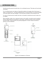
Use this instruction manual to install indoor coil on multipoise furnaces.
The indoor coil is enclosed
in a casing.
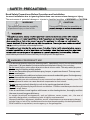
For oil and gas furnaces, the indoor coil should be installed on the supply side of the furnace. A
spacer of a minimum of 4’’ shall be provided between the furnace and the coil to prevent damage
to the drain pan by the heat exchanger. It will also ensure a proper air flow through the coil.
For electric furnaces and air handler the indoor coil should be installed on the return side of the
air handler.
When installing a wider coil on a narrower furnace or air handler, a transition must be installed.
Factory made transitions are available for the Chinook, Supreme & Unique furnaces and Duotec
AHV air handlers. These transitions are specially designed to fit those furnaces and ensure a
perfect fit of the installation.
Typical Coil Installation on Furnace

Page 6
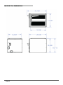
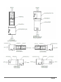
INDOOR COIL DIMENSIONS

Page 7
INSTALLATION
INSPECT EQUIPMENT
File claim with shipper if equipment is
damaged.
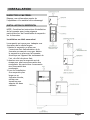
INSTALLATION OF EVAPORATOR COILS
NOTE: Consult the furnace installation
instructions for any special requirements when
installing the coil to the furnace.
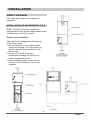
Upflow coil installation
The cased coil is designed to fit furnaces
of the same width.
1.
Set coil in place on oil or gas furnace
supply air opening. Set coil in place on
electric furnace or air handler on the
return side.
2.
Ensure coil is level for proper
condensate drainage. Do not tip coil
toward condensate drain.
3.
When installing wider coil on narrow
furnace, use transition to fit the two
cabinets.

Page 8
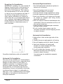
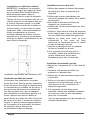
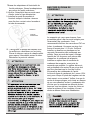
Downflow Coil Installation
IMPORTANT: Installing “A" coils rotated 90
degrees from the front of the furnace in
downflow applications can cause water
blow off or coil freeze up. This is due to
the concentration of air on one coil slab
or lack of air on the opposite coil slab. If
the airflow is high due to ductwork or
other causes, and there is a chance for
water blow off, it is recommended that a
4-in. minimum
fi
eld-supplied adapter be
placed between the coil and the furnace
to allow the air to distribute evenly to
both coil slabs.
4"
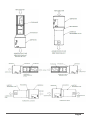
Horizontal Right Installation
1.
Use field fabricated attachment plates to
secure coil to furnace.
2.
Use self-tapping screws to mount
attachment plates to coil casing.
3.
Connect furnace snugly against coil casing.
4.
Use self-tapping screws to attach furnace.
5.
Seal joint between coil casing and furnace
to create an airtight seal using locally
approved materials.
6.
Use cork tape to create air seal between the
undersides of the pan extension and front of
the vertical drain pan.
7.
Install included condensate pan extension
and two corner screws
.
8.
If coil is wider than furnace, use 4-in
minimum transition and self-tapping screws
to attach furnace
.
Horizontal Left Installation
1.
Unbend the 4 tabs at the right side of the
casing.
2.
Connect furnace snugly against coil casing.
3.
Use self-tapping screws to attach furnace.
4.
Seal joint between coil casing and
furnace to create airtight seal using
locally approved materials.
5.
If coil is wider than furnace, use 4-in.
Minimum transition and self-tapping
screws to attach furnace.
See next page for installation example
schematics
Horizontal Coil Installation
The unit can be installed on a work platform,
secured to roof truss in attic, suspended from
hangers on floor joists in crawl space, or
installed on blocks. It is designed to allow
airflow in either direction, to mate with
horizontal-left or horizontal-right furnace
installations. Ensure coil cabinet is level side
to side and front to back. It is allowable to
add up to 1/2-in. additional slope over length
and
depth of coil cabinet in the direction of
drain pan connection.
Downflow installation with coil rotated 90°

Page 9

Page 10
REFRIGERANT LINE CONNECTIONS
For matched and mismatched systems, use line
sizes recommended in outdoor unit Installation
Instructions. Adaptors are supplied with the
outdoor unit as per table below. The
adapters are to be installed on the outdoor
unit connections.
NOTE: Factory nitrogen charge may escape
past rubber plugs during storage. This does
not indicate a leaking coil nor warrant return
of the coil.
Size and install refrigerant lines according
to information provided with outdoor unit.
Coil connection tube sizes are shown in
table below.
Route refrigerant lines to the coil in a
manner that will not obstruct service access
to the unit or removal of the filter.
Do not use damaged, dirty, or contaminated
tubing because it may plug refrigerant
flow-control device. ALWAYS evacuate the
coil and field-supplied tubing before opening
outdoor unit service valves.
The coil can be connected to outdoor units
using field-supplied tubing of refrigerant
grade.
Always evacuate tubing and reclaim
refrigerant when making connections or
flaring tubing.
Leak check connections before insulating
entire suction line.
See Table for coil connection tube size.
1.
Remove cabinet access door.
2.
Remove rubber plugs, suction plug then
liquid plug, from coil stubs using a pulling
and twisting motion. Hold coil stubs steady
to avoid bending or distorting.
3.
Remove tubing plate with rubber
grommets and slide plate with grommets
onto the refrigerant lines (field line-set),
away from braze joints.
4.
Fit refrigerant lines into coil stubs. Wrap a
heat sinking material such as a wet cloth
behind braze joints.
5.
Use 1/2 psig Nitrogen purge in the suction
and out the the liquid line.
6.
Braze using a Sil-Fos or Phos-copper alloy.
Do not use soft solder.
The coil is under pressure and TXV screen is
in place behind liquid line plug. DO NOT
the suction line plug first to depressurize
the coil.
property damage.
do not come in direct contact or allow for
Dissimilar metals can cause galvanic
CAUTION
CONNECT REFRIGERANT, LIQUID,
and SUCTION LINES

Page 11
7.
Braze the adaptors on the outdoor unit end.
Screw the adaptors to the valves of the
outdoor unit.
8.
Leak check connections before
insulating entire suction line.
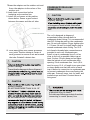
9.
Install the coil sensor at the position
shown below. Ensure a good contact
between the sensor and the coil tube.
10.
Slide tubing plate with rubber grommets
over joints. Position tubing at center of
each grommet to ensure an air seal around
the tube. Reinstall cabinet door
.
The coil is designed to dispose of
accumulated water through built-in
condensate drain fittings. It is recommended
that PVC fittings be used on the condensate
pan. Do not over-tighten. Finger tighten plus
1-1/2 turns. Be sure to install plastic plug in
unused condensate drain fitting. Two 3/4-
inch female threaded pipe connections are
provided in each coil condensate pan.
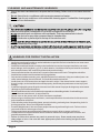
Install a trap in condensate line of coil as
close to the coil as possible. Make trap at
least 3 inches (76 mm) deep and no higher
than the bottom of unit condensate drain
opening. Pitch condensate line 1 inch (25.4
mm) for every 10 ft. of length to an open drain
or sump. Make sure that the outlet of each
trap is below its connection to condensate pan
to prevent condensate from overflowing the
drain pan. Prime all traps, test for leaks, and
insulate traps and lines if located above a
living area
.
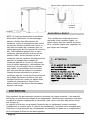
CONDENSATE DRAIN LINE
CONNECTION
in personal injury or death.
Provide trap with air gap in drain line when
connecting to waste (sewer) line.
product damage.
DO NOT BURY MORE THAN 36 IN. OF
on the outdoor unit. If more than the
damage at start-up.
CAUTION
product damage.
To avoid valve damage to the refrigerant
as a wet cloth.
CAUTION
property damage.
or living area, install a field-fabricated
unit.
CAUTION

Page 12
Air Gap Above Liquid Level
Condensate Line
Trap
Sewer Line
NOTE: If unit is located in or above a living
space, where damage may result from
condensate overflow, a field-supplied, external
condensate pan should be installed underneath
the entire unit, and a secondary condensate
line (with appropriate trap) should be run from
the unit into the pan. Any condensate in this
external condensate pan should be drained to
a noticeable place. As an alternative to using
an external condensate pan, some localities
may allow the running of a separate 3/4-inch
(19 mm) condensate line (with appropriate
trap) per local code to a place where the
condensate will be noticeable. The owner of
the structure must be informed that when
condensate flows from secondary drain or
external condensate pan, the unit requires
servicing or water damage will occur. To
further protect against water damage. install a
float switch to shut the unit off if the water in
the secondary pan gets too high.
WASTE LINE CONNECTION
If the condensate line is to be connected to
a waste (sewer) line, an open trap must be
installed ahead of the waste line to
prevent escape of sewer gases.
CARE AND MAINTENANCE
To continue high performance and minimize possible equipment failure, it is essential that
periodic maintenance be performed on this equipment. Consult your local dealer as to the
proper frequency of maintenance, but it should be done at least annually.
The ability to properly perform maintenance on this equipment requires certain mechanical
skills and tools. If you do not possess these, contact your dealer for maintenance. The only
consumer service recommended or required is filter replacement or cleaning on a monthly
basis.
environmental damage.
CAUTION

2022-12-23
Manuel du Propriétaire et
Guide d'installation
Serpentin de climatisation
installation horizontale et verticale
Note importante:
Lire attentivement ce manuel avant d’installer
ou d’utiliser votre nouvelle unité. Conserver ce
manuel pour références futures.

PRÉCAUTIONS DE SÉCURITÉ ........................................................... 3
INTRODUCTION................................................................................... 5
1.
DIMENSIONS DU SERPENTIN ................................................................................ 6
INSTALLATION .................................................................................... 7
2.
INSPECTER L’UNITÉ ......................................................................................... 7
3.
INSTALLATION DU SERPENTIN ............................................................................. 7
4.
RACCORDS DES LIGNES DE RÉFRIGÉRANT ............................................................... 10
5.
RACCORDS DES LIGNES DE RÉFRIGÉRANT, LIQUIDE ET D’ASPIRATION .............................. 10
6.
RACCORD DU DRAIN DE CONDENSAT .................................................................... 11
7.
RACCORD À L’ÉGOUT ...................................................................................... 12
ENTRETIEN ........................................................................................ 12
Table des matières

Page 3
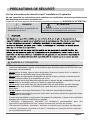
PRECAUTIONS DE SÉCURITÉ
Lire les précautions de sécurité avant l’installation et l’opération
Ne pas connaitre les instructions peut entrainer une installation incorrecte pouvant causer
des dommages sérieux et des blessures.
La gravité de dommages ou des blessures potentiels se classent en DANGER OU ATTENTION.
DANGERS À L’UTILISATION
•
Si une situation anormale survient (comme une odeur de fumée), mettre l’appareil hors
tension immédiatement. Appeler votre technicien pour des instructions afin d’éviter des chocs
électrique, feu ou blessures.
•
Ne pas
insérer de doigt, tiges ou autres objets dans l’entrée ou la sortie d’air. La rotation à
grande vitesse du ventilateur peut causer des blessures.
•
Ne pas
utiliser de vaporisateur inflammable tel que de la laque, peinture ou solvent près de
l’unité. Cela peut causer de la combustion ou un feu.
•
Ne pas
opérer cette unité dans des endroits près ou autour de gaz combustibles. Les gaz
émis peuvent s’accumuler autour de l’unité et cause une explosion.
•
Ne pas
opérer cette unité dans une pièce humide telle que salle de bain ou salle de lavage.
Une exposition trop intense à l’humidité peut causer des courts-circuits aux composants
électriques.
•
Ne pas
exposer votre corps directement à l’air froid pour des périodes prolongées.
•
Ne pas
autoriser des enfants à jouer avec cette unité. Les enfants doivent être supervisés autour
de l’appareil en tout temps.
•
Si cette unite est utilisée en conjunction d’un appareil à combustion, s’assurer d’une ventilation
adequate afin d’éviter une déficience en oxygène.
•
L’utilisation d’équipement spécialisé est hautement recommandée pour des
applications particulières tel que cuisine commerciale ou salle de serveur.
•
Une mauvaise installation, ajustement, alteration ou entretien peut provoquer des dommages
matériels, des blessures corporelles ou la mort. L’installation et l’entretien doit être effectués
par un professionnel licencié.
DANGER
Ce symbole indique la possibilité de
blessures ou de mort.
ATTENTION
Ce symbole indique la possibilité de dommages
matériel ou de conséquences sérieuses
.

Page 4
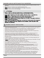
DANGERS LORS DE L’INSTALLATION
•
L’Installation doit être fait par un professionnel licencié. Une installation déficiente peut causer un dégât
d’eau, un choc électrique ou un feu.
•
L’installation doit être faite selon les directives d’installation. Une installation déficiente peut causer un
dégât d’eau, un choc électrique ou un feu.
(
En Amérique du Nord, l’installation doit se faire
conformément avec le NEC (US) et le CEC (Canada) par un personnel autorisé seulement.
•
Contacter un technicien autorisé pour toute réparation ou entretien sur cette unité. Cet appareil doit
être installée conformément aux règles en vigueur de la juridiction.
•
N’utiliser que les accessoires et les pièces spécifiées pour l’installation. L’utilisation de pièces non-
standards peut causer un dégât d’eau, un choc électrique ou un feu et endommager l’unité.
•
Installer l’unité sur une structure pouvant supporter son poids. Si l’endroit choisit ne peut supporter le
poids de l’unité ou que l’installation est incorrecte, l’unité peut tomber et causer des blessures et des
dommages sérieux.
•
Installer les tuyaux de drainage selon les instructions de ce manuel. Un drainage inapproprié peut
causer un dégât d’eau à votre maison et votre propriété.
•
Ne pas
installer l’unité dans un endroit où il peut être exposé à des fuites de gaz combustibles. Si des gaz
combustibles s’accumule autour de l’unité, cela peut causer un feu.
•
Ne pas mettre en marche avant que l’installation soit complétée.
•
Lors du déplacement ou d’une relocalisation de l’unité, consulter un technicien licencié pour la
déconnection et la réinstallation de l’unité.
•
Suivre toutes les normes de sécurité. Porter des lunettes, des vêtements et des gants de protection.
Utiliser un tissu mouillé pour le brasage et garder un extincteur à la portée de la main.
•
Danger de poids excessif. Déplacer et installer l’unité avec deux personnes ou plus. Ne pas le faire
peut entrainer des blessures au dos ou d’autres blessures.
•
Prendre des précautions afin de s’assurer que les tubes d’aluminium ne viennent pas en
contact direct avec des métaux dissemblables ou que l’eau de condensat s’écoule sur un
métal dissemblable. Les métaux dissemblables peuvent entrainer de la corrosion galvanique
et provoquer une défaillance prématurée.
•
Les pièces en tôle peuvent présenter des arêtes vives ou des bavures. Faites attention et
portez des vêtements et des gants de protection appropriés lorsque vous manipulez des
pièces. Le non-respect de cet avertissement peut entraîner des blessures corporelles.
S’assurer que l’eau de condensation se draine sans entrave de l’unité.
DANGERS LORS DU NETTOYAGE ET DE L’ENT
R
ETIEN
•
Fermer l’unité et la mettre hors tension avant le nettoyage. Ne pas le faire peut entrainer un choc
électrique.
•
Ne pas
nettoyer l’unité avec une quantité excessive d’eau.
•
Ne pas
nettoyer l’unité avec des produits de nettoyage combustibles.
•
Cela peut causer un feu ou des dommages.

Page 5
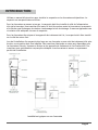
INTRODUCTION
Utilisez ce manuel d'instructions pour installer le serpentin sur les fournaises multipositions. Le
serpentin est encapsulé dans un boîtier.
Pour les fournaises au mazout et au gaz, le serpentin doit être installé du côté de l'alimentation
d'air de la fournaise. Une transition d'au moins 4'' doit être prévue entre la fournaise et le serpentin
afin d'éviter que l'échangeur de chaleur n'endommage le bac de drainage. Il assurera également une
circulation d'air adéquate à travers le serpentin.
Pour les fournaises électriques et les appareils de traitement de l'air, le serpentin doit être installé
sur le côté du retour d'air.
Lors de l'installation d'un serpentin plus large sur une fournaise ou une unité de traitement d'air plus
étroite, une transition doit être installée. Des transitions fabriquées en usine sont disponibles pour
les fournaises Chinook, Supreme et Unique et les appareils de traitement de l'air Duotec AHV. Ces
transitions sont spécialement conçues pour s'adapter à ces fournaises et assurer un ajustement
parfait de l'installation.
Installation typique sur une fournaise

Page 6
DIMENSIONS DU SERPENTIN

Page 7
INSTALLATION
INSPECTER LE MATÉRIEL
Déposer une réclamation auprès de
l'expéditeur si le matériel est endommagé.
INSTALLATION DU SERPENTIN
NOTE: Consultez les instructions d'installation
de la fournaise pour toute exigence
particulière lors de l'installation du serpentin
sur la fournaise.
Installation en débit ascendant
Le serpentin est conçu pour s'adapter aux
fournaises de la même largeur.
1.
Mettre le serpentin en place sur
l'ouverture d'air d'alimentation de la
fournaise au mazout ou au gaz. Mettre
le serpentin en place sur la fournaise
électrique ou l'appareil de traitement de
l'air, du côté du retour d'air.
2.
Assurez-vous que le serpentin est de
niveau pour une bonne évacuation des
condensats. Ne pas incliner le serpentin
vers l'évacuation des
condensats.
3.
Lors de l'installation
d'un serpentin plus
large sur un
fournaise étroite,
utiliser une
transition pour
adapter les deux
cabinets.

Page 8
Installation en débit descendant
IMPORTANT: L'installation de serpentin
tournés à 90 degrés par rapport à l'avant
de la fournaise dans les applications à
débit descendant peut causer un
écoulement d'eau ou le gel du serpentin.
Cela est dû à la concentration d'air sur un
côté du serpentin ou au manque d'air sur
le côté du serpentin opposé. Si le débit
d'air est élevé en raison des conduits ou
d'autres causes, et qu'il existe un risque
d'expulsion d'eau, il est recommandé de
placer un adaptateur de 4 pouces
minimum fabriqué au chantier entre le
serpentin et la fournaise pour permettre
à l'air de se répartir uniformément sur les
deux côtés du serpentin
.
Installation en débit horizontal
L'unité peut être installée sur une plate-
forme de travail, dans le grenier, suspendue
à des cintres sur les solives du plancher dans
le vide sanitaire ou installée sur des blocs. Il
est conçu pour permettre la circulation de
l'air dans les deux sens, afin de s'adapter
aux installations horizontales à gauche ou à
droite. Assurez-vous que le cabinet du
serpentin est de niveau d'un côté à l'autre et
de l'avant à l'arrière. Il est permis d'ajouter
jusqu'à 1/2 pouce de pente supplémentaire
sur la longueur et la profondeur du cabinet
du serpentin dans la direction du
raccordement du bac de drainage
.
Installation horizontale droit
1.
Utiliser des plaques de fixation fabriquées
sur place pour fixer le serpentin à la
fournaise.
2.
Utilisez des vis auto taraudeuses pour
monter les plaques de fixation sur le boîtier
du serpentin.
3.
Raccordez la fournaise au boîtier du
serpentin en l'ajustant bien.
4.
Utilisez des vis auto taraudeuses pour fixer
la fournaise.
5.
Sceller le joint entre le boîtier du serpentin
et la fournaise pour créer un joint étanche à
l'air en utilisant des matériaux approuvés.
6.
Utilisez du ruban pour créer un joint
d'étanchéité à l'air entre les faces
inférieures de l'extension du bac et l'avant
du bac de drainage vertical.
7.
Installez la rallonge de bac à condensat
incluse et les deux vis de coin
.
8.
Si le serpentin est plus large que la
fournaise, utiliser une transition de 4
pouces minimum et des vis auto-
taraudeuses pour fixer la fournaise
.
Installation horizontale gauche
1.
Dépliez les 4 languettes sur le côté droit du
boîtier.
2.
Connecter la fournaise au boîtier du
serpentin en l'ajustant bien.
3.
Utilisez des vis auto taraudeuses pour fixer
la fournaise.
4.
Sceller le joint entre le boîtier du
serpentin et la fournaise pour créer un
joint étanche à l'air en utilisant des
matériaux approuvés.
5.
Si le serpentin est plus large que la
fournaise, utilisez une transition minimale
de 4 pouces et des vis auto taraudeuses
pour fixer la fournaise.
Voir la page suivante pour des exemples de
schémas d'installation.
Installation descendant avec serpentin à 90°
4’’
Page is loading ...
Page is loading ...
Page is loading ...
Page is loading ...
-
 1
1
-
 2
2
-
 3
3
-
 4
4
-
 5
5
-
 6
6
-
 7
7
-
 8
8
-
 9
9
-
 10
10
-
 11
11
-
 12
12
-
 13
13
-
 14
14
-
 15
15
-
 16
16
-
 17
17
-
 18
18
-
 19
19
-
 20
20
-
 21
21
-
 22
22
-
 23
23
-
 24
24


Dettson A Coil Indoor Unit Installation guide
- Category
- Split-system air conditioners
- Type
- Installation guide
Ask a question and I''ll find the answer in the document
Finding information in a document is now easier with AI