Symmons S-4300 Installation guide
- Category
- Sanitary ware
- Type
- Installation guide

Sereno ®
Model Numbers
Sereno Trim Series
Sereno Trim Series with TA-10 Flow Control Spindle & T-12A Cap Assembly
Installation & Operation Instructions
TRIM ONLY
S-4300-TRM
Shower Valve Trim
S-4301-TRM
Shower Trim
S-4302-TRM
Tub/Shower Trim
S-4304-TRM
Tub/Hand Shower Trim
S4308TRM
Shower/Hand Shower Trim
TRIM, TA-10, T-12A
S4300TRM TC
Shower Valve Trim
S4301TRM TC
Shower Trim
S4302TRMTC
Tub/Shower Trim
S4304TRM TC
Tub/Hand Shower Trim
S4308TRM TC
Shower/Hand Shower Trim
S-4300-TRM
S 4300TRMTC
S-4301-TRM
S 4301TRMTC
S-4302-TRM
S 4302TRMTC
S4308TRM
S4308TRM TC
S-4304-TRM
S4304TRMTC
TA-10T-12A
Compliance
• ASME A112.18.1/CSA B125.1
Limited Lifetime - to the original end purchaser in
consumer/residential installations.
5 Years - for industrial/commercial installations.
Refer to www.symmons.com/warranty for complete
warranty information.
Go to www.symmons.com/register to register your
Symmons product.
Warranty

2
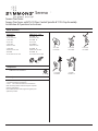
1. Recommended Tools
FIGURE 2
CC
BB
I
I
J
J
L
L
M
M
G
G
D
D
EE
H H
N
N
O
O
P
P
S
S
R
R
Q Q
F
F
Floor
Floor
KK
A
A
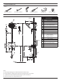
Notes:
1) Valve body and piping not included and shown as reference only.
2) Plaster shield (p/n T-176) for dry wall, plaster or other type walls 1/2" or greater.
3) All dimensions measured from nominal rough-in (see P as reference).
4) Dimensions subject to change without notice.
Phillips Screwdriver
Adjustable Wrench Safety Glasses Thread Seal TapeDrill
Allen Wrench (3mm)
FIGURE 1
2. Dimensions
Measurements
A Ø 2-1/4", 57 mm
B Ø 2-1/4", 57 mm
C 6", 152 mm
D 9-1/4", 235 mm
EFemale 1/2" IPS thread must be
recessed 7/8" from finished wall
F 6", 152 mm right or left
G 77", 1956 mm
H 3-1/2", 89 mm
I 9-1/4", 235 mm
J 5-3/4", 146 mm
K Ø 2-3/8", 60 mm
L
Trim with tub spout:
Ref. 32", 813 mm
Trim without tub spout:
Ref. 42", 1067 mm
M 12", 305 mm
N 4-1/2", 114 mm
O 3-1/4", 83 mm
P(Rough in)
2-3/8" ± 1/2", 60 mm ± 13 mm
Q 1/2" NPT
R 1/2", 13 mm
S 8-1/2", 216 mm

3
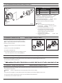
3. Parts Breakdown (Model Numbers Ending in TRMTC)
5. Installation - Adjust Packing Nut (Model Numbers Ending in TRMTC)
1) Turn hot and cold supplies on. Valve will not operate unless both hot and cold water supply pressures are on.
2) Place handle over flow control spindle.
3)
6. Installation - Setting Limit Stop Screw (Model Numbers Ending in TRMTC)
1) Turn hot and cold supplies on. Valve will not operate unless both hot and cold water supply pressures are on.
2) Place handle on flow control spindle and open valve to maximum desired temperature.
3) Turn limit stop screw clockwise until it seats.
WARNING: Failure to adjust limit stop screw properly may result in serious scalding.
The temperature limit stop screw limits valve handle from being turned to maximum position resulting in excessive hot
water discharge temperatures.
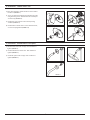
4. Installation - Remove Test Cap (Model Numbers Ending in TRMTC)
1) Check for leaks around the valve assembly and all pipe
fittings.
Flow control spindle (TA-10) and cap assembly (T-12A) will
come factory assembled for all model numbers ending in
TRMTC . When ready to remove Test Cap and install trim,
follow the instructions below:
2) Remove test cap from valve (FIGURE 4.1).
3) If system is dirty, flush valve.
4) Thread flow control spindle and cap assembly into valve
body. Turn clockwise to secure to valve (FIGURE 4.2).
FIGURE 4.1 FIGURE 4.2
LIMIT STOP
SCREW
2
1
PACKING
NUT
FIGURE 3
Replacement Parts
Item Description Part Number
1 Cap Assy. T-12A
2 Flow Control Spindle TA-10
IMPORTANT: Model numbers ending in TRMTC
coordinate with Temptrol pressure balancing valves
ordered with Test Cap. The Test Cap is used to
allow pressurization of system. Do not remove
test cap from valve during wall construction,
installation of valve or pressurization of system.
WARNINGS:
1. Test cap rated for pressure testing up to 200
psi maximum. DO NOT exceed 200 psi while
pressure testing valve body.
2. Do not expose valve with test cap to heat
for longer than 2 minutes when soldering
copper tubing. Doing so may damage the
internal components of the valve and will
void the product warranty.
3. Ensure test cap is re-torqued to 30 lb-ft after
soldering valve body.

4
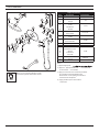
Notes:
1) Append appropriat
2) Append appropriate flow rate to showerhead
or hand showe r for low flow.
3) Apply a bead of silicone around the perimeter
of all shower trim installed flush to the
finished wall. Leave opening on bottom of
escutcheons for weep hole.
4) Apply plumber tape to all threaded
connections.
FIGURE 7
M
AB
C
GH
I
DE
F
J
J
N
P
O
Q
R
S
T
V
U
K
L
EF-109*
*Order in-line vacuum breaker (EF-109) for
hand shower systems without dual checks.
7. Parts Breakdown
Replacement Parts
Item Description Part Number
A Showerhead 432SH
B
C
Shower Arm
Flange 300
D
E
F
G
Plug Button
Screw
Star Washer
Handle
T-251
H
I
Lock Nut
Dome Cover T-19/20-PL
J
K
Shower Escutcheon
Screws T-249A
LDiverter/Volume
Control Handle T-30M
M Tub Spout 432TS
N Hand Shower 432W
O
P
Q
R
S
Cradle Mount
Cradle Mount Screws
Washer
Cradle Arm
Set Screw
T-545
T
U
Wall Elbow
Flange T-444-KIT
V 60" Hose RTS-045

5
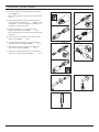
FIGURE 8.4
8. Installation - Shower Valve Trim
1) Place diverter/volume control handle into slot in shower
escutcheon (FIGURE 8.1).
FIGURE 8.1 FIGURE 8.2
FIGURE 8.3
9. Installation - Showerhead & Tub Spout
2) Secure escutcheon to Temptrol pressure balancing valve
using mounting screws. Guide handle into control port
on valve body (FIGURE 8.2).
1) Attach shower arm to stub out pipe. Turn clockwise to
tighten (FIGURE 9.1).
2) Install showerhead to shower arm. Turn clockwise to
tighten (FIGURE 9.2).
3) Install tub spout to stub out pipe. Turn clockwise to
tighten (FIGURE 9.3).
FIGURE 9.1 FIGURE 9.2
FIGURE 9.3
3) Install dome cover and lock nut to valve by turning
clockwise (FIGURE 8.3).
4) Install handle to shower valve. Secure with star washer,
set screw and plug button (FIGURE 8.4).

6
10. Installation - Slide Bar Assembly
1
2
FIGURE 10.1
FIGURE 10.4
1
2
FIGURE 10.5
1
3
FIGURE 10.2
2
1
3
FIGURE 10.3
2
FIGURE 10.6
FIGURE 10.7
4) Attach cradle arm and washer to cradle mount. Secure
with set screw (FIGURE 10.4).
1) Press tab to remove mounting plate from cradle mount
cover (FIGURE 10.1).
Note: Mounting plate center tabs must be horizontal for
removal.
2) Place mounting plate in position, mark and drill 3/16"
holes into drywall. Install anchors (FIGURE 10.2).
Stud Option: Place mounting plate in position, mark
and drill 1/8" pilot holes into stud .
3) Install mounting plate. Secure with two screws.
Replace cradle mount cover (FIGURE 10.3).
Note:
Mounting plate center tabs must be horizontal for
installation.
5) Install wall elbow and flange to recessed pipe fitting.
Turn elbow clockwise to tighten (FIGURE 10.5).
6) Attach small end of hand shower hose to wall elbow.
Turn clockwise to tighten (FIGURE 10.6).
7) Attach large end of hand shower hose to hand shower
wand. Turn clockwise to tighten (FIGURE 10.7).

7
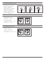
11. Operation (Temperature Control)
1) Turn shower handle counter-clockwise
approximately 1/4 turn to put valve in
cold position (FIGURE 11.1).
2) Turn shower handle counter- clockwise
approximately 1/2 turn to put valve in
warm position (FIGURE 11.2).
3) Turn shower handle counter- clockwise
approximately 3/4 turn to put valve in
hot position (FIGURE 11.3).
FIGURE 11.1 FIGURE 11.2 FIGURE 11.3
12. Operation (VersaFlex™ Diverter Control)
Turn volume control handle
clockwise to increase volume.
Turn volume control handle
counterclockwise to decrease volume.
FIGURE 12.1
TUB/ACCESSORY SHOWER/ACCESSORY
13. Operation (Volume Control)
Turn diverter control handle
clockwise to divert to tub spout or
other Symmons accessory .
Turn diverter control handle
counterclockwise to divert to shower
or other Symmons accessory .
FIGURE 13.1
INCREASE DECREASE

Symmons Industries, Inc. ■ 31 Brooks Drive ■ Braintree, MA 02184 ■ Phone: (800) 796-6667 ■ Fax: (800) 961-9621
Copyright © 2020 Symmons Industries, Inc. ■ symmons.com ■ [email protected] ■ ZV-3416 REV 0 ■ 030220
WARNING: This product can expose you to chemicals including lead, which is known to the state of California to cause cancer, birth
defects, or other reproductive harm. For more information, go to www.P65Warnings.ca.gov.
14. Troubleshooting Chart
Problem Cause Solution
Finish is spotting. Elements in water supply may cause cloth using mild soap and water or a
non-abrasive cleaner and then quickly
rinse with water.
-
 1
1
-
 2
2
-
 3
3
-
 4
4
-
 5
5
-
 6
6
-
 7
7
-
 8
8


Symmons S-4300 Installation guide
- Category
- Sanitary ware
- Type
- Installation guide
Ask a question and I''ll find the answer in the document
Finding information in a document is now easier with AI