Page is loading ...

Dell™ PowerEdge™ C1100
Systems
Hardware Owner’s
Manual
Regulatory Model CS24-TY
book.book Page 1 Tuesday, February 26, 2013 11:33 AM

Notes, Cautions, and Warnings
NOTE: A NOTE indicates important information that helps you make better use of
your computer.
CAUTION: A CAUTION indicates potential damage to hardware or loss of data if
instructions are not followed.
WARNING: A WARNING indicates a potential for property damage, personal
injury, or death.
____________________
© 2013 Dell Inc. All rights reserved.
Trademarks used in this text: Dell™ and the DELL logo are trademarks of Dell Inc.
Regulatory Model CS24-TY
2013 - 02 Rev. A01
book.book Page 2 Tuesday, February 26, 2013 11:33 AM

book.book Page 3 Tuesday, February 26, 2013 11:33 AM

book.book Page 4 Tuesday, February 26, 2013 11:33 AM

Contents 5
Contents
1 About Your System. . . . . . . . . . . . . . . . . . 13
Accessing System Features During Startup. . . . . . . 13
Front-Panel Features and Indicators
. . . . . . . . . . 14
Hard-Drive Indicator Patterns . . . . . . . . . . . . . . 18
Back-Panel Features and Indicators
. . . . . . . . . . 19
NIC Indicator Codes
. . . . . . . . . . . . . . . . . . . 20
Power and System Board Indicator Codes . . . . . . . 21
POST Error Codes
. . . . . . . . . . . . . . . . . . . . 23
Beep Codes
. . . . . . . . . . . . . . . . . . . . . . . 33
Post Beep Codes
. . . . . . . . . . . . . . . . . . . . . 34
Other Information You May Need . . . . . . . . . . . . 34
2 Using the System Setup Program . . . . . . 35
Start Menu . . . . . . . . . . . . . . . . . . . . . . . . 35
System Setup Options at Boot
. . . . . . . . . . . . . . 36
Console Redirection
. . . . . . . . . . . . . . . . . . . 36
Main Menu
. . . . . . . . . . . . . . . . . . . . . . . . 37
Main Screen
. . . . . . . . . . . . . . . . . . . . 37
AMIBIOS Settings
. . . . . . . . . . . . . . . . . 37
book.book Page 5 Tuesday, February 26, 2013 11:33 AM

6 Contents
Processor Settings . . . . . . . . . . . . . . . . . 38
System Memory Settings . . . . . . . . . . . . . . 38
Advanced Menu . . . . . . . . . . . . . . . . . . . . . 38
Processor Configuration
. . . . . . . . . . . . . . 38
Memory Configuration . . . . . . . . . . . . . . . 40
IDE Configuration
. . . . . . . . . . . . . . . . . . 40
Super IO Configuration
. . . . . . . . . . . . . . . 41
USB Configuration . . . . . . . . . . . . . . . . . 41
PCI Configuration
. . . . . . . . . . . . . . . . . . 41
Boot Menu
. . . . . . . . . . . . . . . . . . . . . . . . 43
Boot Settings Configuration
. . . . . . . . . . . . 43
Server Menu . . . . . . . . . . . . . . . . . . . . . . . 44
BMC LAN Configuration
. . . . . . . . . . . . . . 45
Remote Access Configuration . . . . . . . . . . . 46
Security Menu . . . . . . . . . . . . . . . . . . . . . . 47
Exit Menu
. . . . . . . . . . . . . . . . . . . . . . . . . 47
3 Installing System Components . . . . . . . 49
Safety Instructions . . . . . . . . . . . . . . . . . . . . 49
Recommended Tools
. . . . . . . . . . . . . . . . . . . 49
Inside the System. . . . . . . . . . . . . . . . . . . . . 50
Hard Drives
. . . . . . . . . . . . . . . . . . . . . . . . 51
Removing a Hard-Drive Blank
. . . . . . . . . . . 51
Installing a Hard-Drive Blank
. . . . . . . . . . . . 52
Removing a Hard Drive From a Hard-Drive
Carrier
. . . . . . . . . . . . . . . . . . . . . . . . 52
book.book Page 6 Tuesday, February 26, 2013 11:33 AM

Contents 7
Installing a Hard Drive Into a Hard-Drive
Carrier
. . . . . . . . . . . . . . . . . . . . . . . 53
Removing a Hard-Drive Carrier
. . . . . . . . . . . 54
Installing a Hard-Drive Carrier
. . . . . . . . . . . 54
Opening and Closing the System
. . . . . . . . . . . . 55
Opening the System
. . . . . . . . . . . . . . . . 55
Closing the System
. . . . . . . . . . . . . . . . . 56
Cooling Shroud
. . . . . . . . . . . . . . . . . . . . . . 56
Removing the Cooling Shroud
. . . . . . . . . . . 56
Installing the Cooling Shroud
. . . . . . . . . . . . 57
Heat Sinks
. . . . . . . . . . . . . . . . . . . . . . . . 58
Removing the Heat Sink
. . . . . . . . . . . . . . 58
Installing the Heat Sink
. . . . . . . . . . . . . . . 59
Processor
. . . . . . . . . . . . . . . . . . . . . . . . 60
Removing the Processor
. . . . . . . . . . . . . . 60
Installing the Processor
. . . . . . . . . . . . . . 61
System Memory
. . . . . . . . . . . . . . . . . . . . . 63
General Memory Module Installation
Guidelines
. . . . . . . . . . . . . . . . . . . . . . 63
Mode-Specific Guidelines
. . . . . . . . . . . . . 64
Memory Socket Location on the System Board
. . 65
Supported Memory Configuration . . . . . . . . . 66
Removing Memory Modules
. . . . . . . . . . . . 67
Installing Memory Modules
. . . . . . . . . . . . 68
Expansion-Card Riser and Expansion Card
. . . . . . . 69
Removing the Expansion-Card Riser
. . . . . . . . 69
Installing the Expansion-Card Riser
. . . . . . . . 70
Removing the Expansion Card
. . . . . . . . . . . 71
Installing the Expansion Card
. . . . . . . . . . . 72
book.book Page 7 Tuesday, February 26, 2013 11:33 AM

8 Contents
RAID Battery (Optional) . . . . . . . . . . . . . . . . . 73
Removing a RAID Battery
. . . . . . . . . . . . . . 73
Installing a RAID Battery . . . . . . . . . . . . . . 73
Integrated Storage Controller Cards. . . . . . . . . . . 75
Removing the Integrated
Storage Controller Card
. . . . . . . . . . . . . . . 75
Installing the Integrated
Storage Controller Card
. . . . . . . . . . . . . . . 76
Mezzanine Card (10 GbE LAN)
. . . . . . . . . . . . . . 77
Removing the Mezzanine Card (10 GbE LAN)
. . . . 77
Installing the Mezzanine Card (10 GbE LAN)
. . . . 79
Power Supplies
. . . . . . . . . . . . . . . . . . . . . 80
Removing the Non-Redundant Power Supply
. . . 80
Installing the Non-Redundant Power Supply
. . . . 81
Removing the Redundant Power Supply . . . . . . 82
Installing the Redundant Power Supply
. . . . . . 83
Power Distribution Board
. . . . . . . . . . . . . . . . 83
Removing the Power Distribution Board
. . . . . . 83
Installing the Power Distribution Board
. . . . . . 84
Cooling Fans
. . . . . . . . . . . . . . . . . . . . . . . 85
Removing a Cooling Fan Assembly
. . . . . . . . . 85
Installing the Cooling Fan Assembly
. . . . . . . . 86
Expander Board
. . . . . . . . . . . . . . . . . . . . . 87
Removing the Expander Board
. . . . . . . . . . . 87
Installing the Expander Board
. . . . . . . . . . . 89
Backplane
. . . . . . . . . . . . . . . . . . . . . . . . 89
Removing the Backplane
. . . . . . . . . . . . . . 89
Installing the Backplane
. . . . . . . . . . . . . . 91
book.book Page 8 Tuesday, February 26, 2013 11:33 AM

Contents 9
Control Panel (Optional) . . . . . . . . . . . . . . . . . 91
Removing the Control Panel
. . . . . . . . . . . . 91
Installing the Control Panel. . . . . . . . . . . . . 92
Control Panel Assembly (Optional) . . . . . . . . . . . 92
Removing the Control Panel Assembly
. . . . . . . 92
Installing the Control Panel Assembly . . . . . . . 93
System Battery . . . . . . . . . . . . . . . . . . . . . . 94
Removing the System Battery
. . . . . . . . . . . 94
Installing the System Battery . . . . . . . . . . . . 95
System Board . . . . . . . . . . . . . . . . . . . . . . 96
Removing the System Board
. . . . . . . . . . . . 96
Installing the System Board . . . . . . . . . . . . 97
4 Troubleshooting Your System . . . . . . . . . 99
Safety First—For You and Your System . . . . . . . . . 99
Installation Problems
. . . . . . . . . . . . . . . . . . 99
Troubleshooting System Startup Failure
. . . . . . . . 100
Troubleshooting External Connections
. . . . . . . . . 100
Troubleshooting the Video Subsystem
. . . . . . . . . 100
Troubleshooting a USB Device
. . . . . . . . . . . . . 100
Troubleshooting a Serial I/O Device
. . . . . . . . . . 101
Troubleshooting a NIC
. . . . . . . . . . . . . . . . . . 102
Troubleshooting a Wet System
. . . . . . . . . . . . . 103
Troubleshooting a Damaged System
. . . . . . . . . . 104
book.book Page 9 Tuesday, February 26, 2013 11:33 AM

10 Contents
Troubleshooting the System Battery . . . . . . . . . . 104
Troubleshooting Power Supplies
. . . . . . . . . . . 105
Troubleshooting System Cooling Problems
. . . . . . 106
Troubleshooting a Fan . . . . . . . . . . . . . . . . . 106
Troubleshooting System Memory
. . . . . . . . . . . 107
Troubleshooting a Hard Drive
. . . . . . . . . . . . . 109
Troubleshooting a Storage Controller . . . . . . . . . 110
Troubleshooting Expansion Cards
. . . . . . . . . . . 111
Troubleshooting Processors
. . . . . . . . . . . . . . 112
IRQ Assignment Conflicts . . . . . . . . . . . . . . . 113
Troubleshooting Changes in BIOS Settings
. . . . . . 114
Collecting System Event Log for Investigation
. . . . 114
5 Jumpers and Connectors. . . . . . . . . . . . 115
System Board Connectors . . . . . . . . . . . . . . . 115
Jumper Settings
. . . . . . . . . . . . . . . . . . . . 116
System Configuration Jumper Settings
. . . . . . 116
Backplane Jumper Settings
. . . . . . . . . . . . . . 118
Backplane Connectors
. . . . . . . . . . . . . . . . . 119
3.5-Inch Hard Drives
. . . . . . . . . . . . . . . 119
2.5-Inch Hard Drives
. . . . . . . . . . . . . . . 120
Power Distribution Board
. . . . . . . . . . . . . . . 122
book.book Page 10 Tuesday, February 26, 2013 11:33 AM

Contents 11
6 Getting Help. . . . . . . . . . . . . . . . . . . . . . 123
Contacting Dell . . . . . . . . . . . . . . . . . . . . . 123
Glossary . . . . . . . . . . . . . . . . . . . . . . . . . . . . 125
Index . . . . . . . . . . . . . . . . . . . . . . . . . . . . . . 135
book.book Page 11 Tuesday, February 26, 2013 11:33 AM

12 Contents
book.book Page 12 Tuesday, February 26, 2013 11:33 AM

About Your System 13
1
About Your System
Accessing System Features During Startup
The following keystrokes provide access to system features during startup.
Keystroke Description
<F2> Enters the System Setup program. See "Start Menu" on page 35.
<F11> Enters the BIOS Boot Manager. See "System Setup Options at Boot"
on page 36.
<F12> Starts Preboot eXecution Environment (PXE) boot.
<Ctrl><C> Enters the SAS Configuration Utility. For more information,
see the SAS adapter documentation.
<Ctrl><R> Enters the RAID configuration utility. For more information,
see the documentation for your SAS RAID card.
<Ctrl><S> Enters the utility to configure NIC settings for PXE boot. For more
information, see the documentation for your integrated NIC.
book.book Page 13 Tuesday, February 26, 2013 11:33 AM
14 About Your System
Front-Panel Features and Indicators
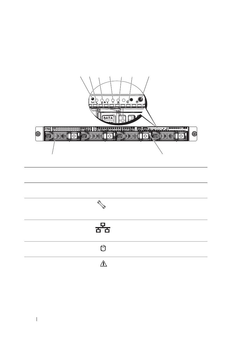
Figure 1-1. Front-Panel Features—3.5-Inch Hard-Drive System
Item Indicator, Button,
or Connector
Icon Description
1 Reset button Restarts the system while the system is
powered on.
2 Service LED Lights when the BMC port is on and
blinks when there is traffic on the
BMC port.
3 Ethernet connectors 1
and 2
Lights green when a connection is made
to the NIC port, blinks when there is
traffic on the NIC port.
4 Hard drive activity
LED
Lights when the hard drives are active.
5 Fault LED Displays status/errors and is controlled
by BMC.
9
8
1
2
3
4
5
6
7
book.book Page 14 Tuesday, February 26, 2013 11:33 AM
About Your System 15
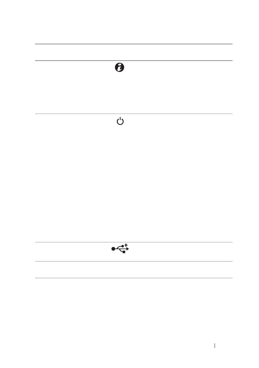
6 System identification
indicator/button
The system identification button can
be used to locate a particular system
and system board within a rack.
When the button is pushed, the blue
system status indicators on the front
and the back blink until the button
is pushed again.
7Power-on
indicator/power
button
The power-on indicator lights
when the system power is on.
The power button controls the
DC power supply output to the system.
NOTE: When powering on the system,
the video monitor can take from several
seconds to over 2 minutes to display an
image, depending on the amount of
memory installed in the system.
NOTE: On ACPI-compliant operating
systems, turning off the system using the
power button causes the system to
perform a graceful shutdown before
power to the system is turned off.
NOTE: To force an ungraceful shutdown,
press and hold the power button for
5 seconds.
8 USB connectors (2) Connects USB devices to the system.
The ports are USB 2.0-compliant.
9 Hard drives Up to four hot-swappable 3.5-inch hard
drives.
Item Indicator, Button,
or Connector
Icon Description
book.book Page 15 Tuesday, February 26, 2013 11:33 AM
16 About Your System
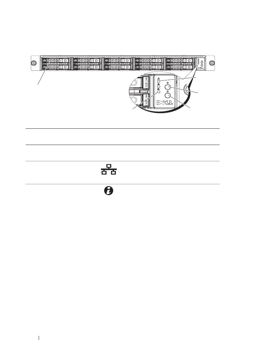
Figure 1-2. Front-Panel Features—2.5-Inch Hard-Drive Systems
Item Indicator, Button,
or Connector
Icon Description
1 Hard drives Up to ten hot-swappable 2.5-inch hard
drives.
2 Ethernet connectors 1
and 2
Lights green when a connection is
made to the NIC port, blinks when
there is traffic on the NIC port.
3 System identification
indicator/button
The system identification button can be
used to locate a particular system and
system board within a rack.
When the button is pushed, the blue
system status indicators on the front
and the back blink until the button
is pushed again.
1
5
4
3
2
book.book Page 16 Tuesday, February 26, 2013 11:33 AM

About Your System 17
4Power-on
indicator/power
button
The power-on indicator lights
when the system power is on.
The power button controls the
DC power supply output to the system.
NOTE: When powering on the system,
the video monitor can take from several
seconds to over 2 minutes to display an
image, depending on the amount of
memory installed in the system.
NOTE: On ACPI-compliant operating
systems, turning off the system using the
power button causes the system to
perform a graceful shutdown before
power to the system is turned off.
NOTE: To force an ungraceful shutdown,
press and hold the power button for
5 seconds.
5 Fault LED Displays status/errors and is controlled
by BMC.
Item Indicator, Button,
or Connector
Icon Description
book.book Page 17 Tuesday, February 26, 2013 11:33 AM

18 About Your System
Hard-Drive Indicator Patterns
Figure 1-3. Hard-Drive Indicators
Table 1-1. Hard Drive Indicators—On-Board SATA Ports
1 hard-drive activity indicator
(green)
2 hard-drive status indicator
(green and amber)
Drive-Activity Indicator/Drive-Status Indicator Condition
Off/Off No drive
Steady green/Off No access
Steady green/Steady green Drive online
Steady green/Blinks green Drive is present or in idle stage
Table 1-2. Hard Drive Indicators—SAS/SATA Add-on Cards
Drive-Activity Indicator/Drive-Status Indicator Condition
Off/Off No drive
Steady green/Off No access
Steady green/Steady green Drive online
1
2
1
2
2.5-inch hard-drive carrier
3.5-inch hard-drive carrier
book.book Page 18 Tuesday, February 26, 2013 11:33 AM

About Your System 19
Back-Panel Features and Indicators
Figure 1-4. Back-Panel Features
Steady green/Blinks green Drive is present or in idle stage
Steady amber/Off Drive failed
Steady amber/Steady green Drive rebuilding
Item Indicator, Button, or
Connector
Icon Description
1 Power supply 650 W
2 Power LED Lights green when the power supply is
functioning properly.
3 Fault LED Displays status/errors and is controlled
by BMC.
4 System identification
indicator
Both the systems management software
and the identification buttons located
on the front can cause the indicator to
flash blue to identify a particular
system and system board.
Lights amber when the system needs
attention due to a problem.
5 Serial connector Connects a serial device to the system.
6 Video connector Connects a VGA display to the system.
Table 1-2. Hard Drive Indicators—SAS/SATA Add-on Cards
(continued)
Drive-Activity Indicator/Drive-Status Indicator Condition
1
45
6
78
9
3
2
10
book.book Page 19 Tuesday, February 26, 2013 11:33 AM
20 About Your System
NIC Indicator Codes
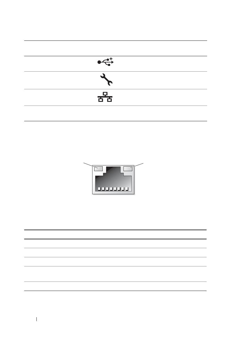
Figure 1-5. NIC Indicators
Table 1-3. NIC Speed Indicator Codes
7 USB connectors (2) Connects USB devices to the system.
The ports are USB 2.0-compliant.
8 KVM over IP Port Dedicated management port.
9 Ethernet connectors (2) Embedded 10/100/1000 NIC connector.
10 Mezzanine-card cover Remove this cover before installing
mezzanine card.
1 link indicator 2 activity indicator
NIC Speed Indicator Condition
Steady amber Link at 1 Gbps
Blinks amber Identify port with 1 Gbps connection
Steady green Link at 100 Mbps
Blinks green Identify port with 10 Mbps or 100 Mbps
connection
Green off Link at 10 Mbps
Item Indicator, Button, or
Connector
Icon Description
1
2
book.book Page 20 Tuesday, February 26, 2013 11:33 AM
/
