Page is loading ...

1
SEQUENCE OF OPERATION
RECOMMENDED LOCATION
TEMPERATURE AND SAFETY REQUIREMENTS
HUMIDIFIER MOUTING LOCATION
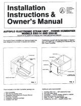
Installation Instructions
Owner’s Manual
STEP BY STEP INSTALLATION
DRILL MOUNTING HOLES AND CUT OPENING
MODEL SC-15
MOUNTING HUMIDIFIER
HUMIDISTAT MOUNTING LOCATION
MODEL SC-15 & MODEL 250
FLOW-THRU HUMIDIFERS
Refer to the rating plate on the furnace for minimum
clearances to combustible construction. All parts
and connections of an AUTOFLO humidifier must
be installed outside of the minimum clearance
requirements for rear, top, sides, and flue of furnace.
Do not install where humidifier or water connections
may be exposed to freezing temperatures or outside
weather. Attic installations are NOT recommended.
If you have central air conditioning, carefully plan
the location of the plenum opening to prevent
damage to the cooling coil or other components
inside the duct.
The AUTOFLO model SC-15, is to be mounted on
the supply duct of the furnace only. Model 250 can
be mounted on the supply or the return duct of the
furnace.
The AUTOFLO Model’s SC-15 & 250 use the evapo
-
rative principal to add moisture to the warm air heat
-
ing system. Upon a demand for humidity from the
humidity control, the water solenoid valve opens and
water flows in at the top of the media pad and is
evaporated, as warm air passes through the media
pad. When the moisture laden air re-enters the duct
it is mixed with dry air already flowing through the
duct. This moisture laden air gradually increases the
relative humidity level in the home.
CAUTION: Installation should be performed by
qualified personnel only. Use eye protection and
gloves when drilling and handling sheet metal. All
work must be performed to local & national codes
and ordinances. Use multi-conductor 18 awg solid
copper wire. Provide over-current protection as
required. DO NOT omit the drain or overflow tubing.
Turn off power to the furnace before installing the
humidifier. Test fit the SC-15 housing on the side of
the warm air plenum. Before proceeding, verify that
adequate clearances are available for servicing the
media pad. There must also be adequate room (5
1/2 inches) inside the plenum for the louver. If
necessary, relocate the unit. Use a plumb line or a
level to make sure the housing is level. With a
permanent marker outline the inside edge of the
housing. Also mark the twelve holes to be drilled.
Center punch and drill all twelve holes as indicated
by the marks. Drill or punch a starter hole and then
use tin snips to cut out the rectangular shaped open
-
ing. The opening should be 1/8 inch larger on all
four sides than what was marked.
Hold the housing next to to duct and start four #8 x
3/4 inch long sheet metal screws through the holes
in the bottom edge of the humidifier. With these four
screws started the unit should remain in place while
starting the other eight screws. With all twelve of
the screws started they can now be tightened. With
the housing mounted the louver can be installed.
This should be done by rotating the louver to the
proper position depending on the direction of air
flow. The air flow should enter into the curved
multi-louvers and exit out of the large opening.
The humidistat can be mounted on the cold air return
duct to sense the cool dry air returning to the
furnace. It can also be mounted on an interior wall
near the furnace thermostat as well. The electrical
connections and basic wiring are the same for duct
mounted or wall mounted humidistats.
TB 218 Part#090375A0218 Rev. B 12122006SC15250
FOR USE WITH GAS, OIL, and HYDRONIC FORCED AIR FURNACES
®
Copyright 2007 © , All Rights Reserved
281 Keyes Ave. Hampshire, IL 60140 • 847-683-7990 • Fax 847-683-7301 • www.bestairpro.com
®

2
Mount the model 250 using all the same precau-
tions as in mounting the SC-15. Use the mounting
template to locate the humidifier on the duct work.
Tape down the template for the humidifier and for
the by pass duct adaptor. Drill and cut all holes that
go with each template. Mount the adaptor and the
baffle with the (6) 3/8” screws from the kit. Mount
the humidifier by first putting in the bottom of the
humidifier housing to catch the lip on the back of the
housing. Then use the (10) 1/2” screws that come
in the kit to mount the housing to the duct. Install
the field supplied bypass duct and end cap. First
route the bypass duct from the duct adaptor to one
side of the humidifier housing. Drill 2 holes through
the bypass duct and the duct adaptor. Install (2)
3/8” screws from the kit on each end of the humidi
-
fier housing. There are pre-punched holes. Use
them to line up and mount the bypass duct and end
cap with (2) 1/2” screws from the kit. Open the
Bypass Baffle during the winter and close it during
the summer.
®
Copyright 2007 © , All Rights Reserved
281 Keyes Ave. Hampshire, IL 60140 • 847-683-7990 • Fax 847-683-7301 • www.bestairpro.com
®
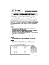
DRILL MOUNTING HOLES AND CUT
OPENING MODEL 250
Model 250
Bypass baffle
and duct adaptor.
Mounting the
Model 250
250
Down Flow
Supply Duct
250
Up Flow
R etur n Duc t
250
Return
Duct
Supply
Duct
BY PASS
Horizontal flow
Place
Baffle
Here
SC-15 mounts
to th
e supply
duct only.
Horizontal flow
SC-15
Blower
Motor
Side Cutaway View
Model SC-15 mounted
on the supply plenum
of an Upflow Furnace
Up Flow
SC -15

3
PARTS LIST
MODEL SC-15
1. Model SC-15 Humidifier
2. Small parts bag containing:
a. Two #8 x 3/4” sheet metal screws
b. Twelve #8 x 3/8” sheet metal screws
3. Saddle tapping valve kit
4. 24 volt humidistat
5. 24 volt transformer
6. 1/2” drain hose
7. 1/4” plastic tubing
8. Evaporative media pad
9. Owner’s manual
ADDITIONAL RECOMMENDED PARTS
1. Relay, with 120 volt current sensing coil for furnaces
with multi-speed blower motors.
2. 4x4 wire box to mount transformer and enclose line
voltage connections.
3. #18awg thermostat wire to make up any and all
24 volt connections
4. 1/2” drain hose clamp.
Copyright 2007 © , All Rights Reserved
281 Keyes Ave. Hampshire, IL 60140 • 847-683-7990 • Fax 847-683-7301 • www.bestairpro.com
®
®
Unpack the Autoflo model SC-15 humidifer and familiarize yourself with the following parts:

4
PARTS LIST
MODEL 250
1. Model 250 Humidifier
2. Evaporative pad with holder.
3. Mounting template (not shown)
4. 24 volt transformer
5. 1/4” plastic water tubing
6. Saddle valve tapping kit
7 & 8. Small parts bag containing
a. Six #6 x 1/2” sheet metal screws
b. Sixteen #8 x 3/8” sheet metal screws
9. By pass adaptor template (not shown)
10. Baffle
11. End cap
12. Duct adaptor
13. Two wire nuts (not shown)
14. 1/2” draing tubing
15. 24 volt humidistat
16. Owner’s manual
ADDITIONAL REQUIRED OR RECOMMENDED PARTS
1. Bypass duct material 6” diameter metal.
2. Relay, with 120 volt current sensing coil for multi-speed
blower motors.
3. 4x4 wire box to mount transformer and enclose line
voltage connetions
4. #18awg thermostat wire to make up any and all
24 volt connections
5. 1/2” drain hose clamp.
Copyright 2007 © , All Rights Reserved
281 Keyes Ave. Hampshire, IL 60140 • 847-683-7990 • Fax 847-683-7301 • www.bestairpro.com
®
®
Unpack the Autoflo model 250 humidifer and familiarize yourself with the following parts:

C
T40-VA
24VAC 40VA
OR EQUIVALENT
5
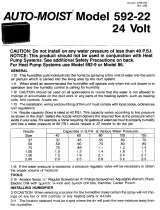
ELECTRICAL CONNECTIONS
MODEL SC-15 & MODEL 250 FLOW-THRU HUMIDIFIERS
The transformer should be wired in parallel with the
furnace blower motor line voltage. This will allow the
humidifier to run only when there is a call for fan.
The transformer is designed to be attached to a 4”
square outlet box. The electrical box must be
mounted and wired in accordance with local building
codes & the National Electrical Code. SHUT OFF
THE POWER TO THE FURNACE BEFORE PRO
-
CEEDING! NOTE1: Check wiring in furnace for
humidifier (HUM) terminals. If present, check to see
if it is 120vac or 24vac. If it is 120vac, connect the
transformer primary leads to these terminals. If it is
24vac, you do not need the transformer. Simply
connect one side of the humidistat to one HUM
terminal and the other HUM terminal to the solenoid
valve of the humidifier. Then make the last connec
-
tion of the solenoid valve to the humidistat. If you
are using the transformer you will need to connect
the 24vac common from the transformer to one of
the solenoid valve wires and then the 24vac hot from
the transformer to the humidistat. Then from the
humidistat to the other wire on the solenoid valve.
Make sure not to route wires where they can be
burned or chaffed. See example wiring solutions to
the right of this page.
OPERATIONAL CHECK
With the humidistat set to its highest setting the
humidifier solenoid should open shortly after the
furnace blower is activated. If solenoid does not
open refer to troubleshooting guide in this manual.
CAUTION: Check the transformer, the solenoid
valve and humidistat as well as all field wiring
connections as they could be at fault.
A qualified Electrician should be consulted to
determine if 24 vac is present at the solenoid and
at the humidistat, and that line voltage is present
at the transformer.
WIRING FOR MOST COMMON FURNACES
WIRING FOR MOST COMMON 2 STAGE OR
VARIABLE SPEED FURNACES
T40-VA
24VAC 40VA
OR EQUIVALENT
C
H
HUMIDISTAT
L1
L2
Solenoid Valve on
Model SC15 or 250
To Motor current sensing
relay NO Contact
TO
LINE
VOLTAGE
HUMIDISTAT
If the HUM terminals
in the furnace are
24vac, don’t use the
transformer! Simply
connect to the HUM
terminals as shown.
HUM
H
HUM
To 120 vac HUM
terminals in furnace.
See Note 1.
Copyright 2007 © , All Rights Reserved
281 Keyes Ave. Hampshire, IL 60140 • 847-683-7990 • Fax 847-683-7301 • www.bestairpro.com
®
®
Solenoid Valve on
Model SC15 or 250

6
WATER CONNECTION
Water supply for the humidifier should be taken from
a nearby hot water line but cold water is acceptable.
All water connections should be made at ground
floor level. Do not use any water line served by a
water softener. If your home has a water softener,
make the water connection up stream of the water
softener. A water softener is not a de-mineralizer. It
merely exchanges various hard-ions for soft-ions in
the water. These soft-ions or minerals, will build up
in the transfer media in the humidifier, causing the
need for more frequent servicing. The evaporation
of softened water may also produce a white powder
which may be carried in to the duct system and
ultimately in to the home. The saddle tapping valve
should be mounted on top of, or on the side of the
water line. If the valve is installed on the bottom of
the water line it could clog with sediment from the
water line. Refer to the instructions on the saddle
valve package and proceed as follows. For copper
water lines the valve is self piercing. Mount the
saddle valve to the top or side of the water line, then
turn “T” handle to the clockwise until it stops to
pierce and seat the valve to the pipe. Open to flush
the valve and close it again. Then connect plastic
water line from the valve to the humidifier making
sure not to kink it or run it near any hot flue pipes.
Connect water line to valve and humidifier with
supplied hardware. Now open the saddle valve turn
-
ing the tee handle counter clockwise until fully open.
Check for water leaks and repair as necessary.
Attic installations are not recommended
INSTALL DOOR AND EVAPORATIVE PAD
DRAIN CONNECTION
Make sure the evaporative pad is positioned in the
door correctly. The black mark on the edge of the
pad indicates the top. The pad slides into the door
and rests against the four legs located inside.
Position the bottom edge of the door in the tray
located on the lower opening in the housing. Then
simply push the top of door closed until is has
snapped into place. To remove door just push down
on the two tabs located at the top of the door and pull
the door away from the housing.
Connect the 1/2” plastic tubing to the drain spout
and secure it. The spout is located at the bottom of
the housing. Keep the tubing as short as possible
and avoid sharp bends. The drain line should be
routed on a continous downward slope and into a
suitable drain. WARNING: failure to connect the
drain tubing could result in a flood.
SETTING THE HUMIDISTAT
Most people feel comfortable between 35% to 45%
RH, but the proper relative humidity for your home
depends upon many factors such as outside air
temperature, type, and placement of insulation,
vapor barrier, effectiveness of weather stripping,
type of windows and doors (including frames and
jams), and whether storm windows and doors are
used. With all of these variables it is nearly impos
-
sible to recommend a proper humidity setting. The
best humidstat setting is one that you are comfort
-
able with. Also, as the outdoor temperature fluctu
-
ates, it may be necessary to adjust the humidity
level a few times during the heating season. Refer
to the “Relative Humidity Chart” as a starting point
for your proper humidistat setting. Generally, in a
tighter and better insulated house, the humidistat
may be set higher than in a drafty, uninsulated
house.
Copyright 2007 © , All Rights Reserved
281 Keyes Ave. Hampshire, IL 60140 • 847-683-7990 • Fax 847-683-7301 • www.bestairpro.com
®
®
MODEL SC-15 & MODEL 250 FLOW-THRU HUMIDIFIERS
INSTALL HUMIDISTAT
The Autoflo Humidistat should be installed as
described in the installation instructions supplied
with the humidistat.

7
DO NOT OVER - HUMIDIFY
MAINTENANCE
Cold air cannot hold as much moisture as warm air.
Any cold drafts or cold-faces such as windows and
doors (including frames and jams) may cause water
vapor to condense at these points. Also, if your
home is well-insulated and weather-stripped but
lacks effective vapor barriers, water may seep
through the walls and ceilings. This moisture may
condense either inside or outside the walls or in the
attic. If any of these conditions are observed, the
humidity level should be reduced before water
damage occurs.
RELATIVE HUMIDITY CHART
Suggested Humidistat Settings
OUTDOOR
TEMPERATURE
ADJUST
%RH TO
+30°F
+20°F
+10°F
+0°F
-9°F
40%
35%
30%
25%
20%
Table 1. Suggested RH set points for different outdoor temperatures
All power humidifiers require some mainte-
nance to keep them operating at peak perfor
-
mance. The autoflo models SC-15 & 250 humidi
-
fiers have been designed to simplify required
maintenance.
FOR the MODEL SC-15
1. Semi-annual or annual replacement of the
evaporator pad.
2. An annual cleaning, general inspection, and shut
down of the unit at the end of the heating season.
3. The evporative pad should be replaced when it
starts to look white and chalky. Replace it with a
catalog #SC-EP pad.
FOR the MODEL 250
1. Semi-annual or annual replacement of the
evaporator pad.
2. An annual cleaning, general inspection, and shut
down of the unit at the end of the heating season.
The replacement pad catalog # is 40EP for pad
with holder.
Copyright 2007 © , All Rights Reserved
281 Keyes Ave. Hampshire, IL 60140 • 847-683-7990 • Fax 847-683-7301 • www.bestairpro.com
®
®

8
SYMPTOM
T R O U B L E S H O O T I N G
POSSIBLE CAUSES & REMEDIES
Water does not flow when solenoid
is energized.
1. Saddle valve “T” handle is not open.
2. Saddle valve is clogged with mineral buildup.
3. Solenoid valve inlet screen is clogged.
4. Solenoid valve is stuck closed.
Solenoid will not energize.
1. Humidity control is not set high enough.
2. Control transformer has failed
3. HVAC system is not in the heating mode.
4. Fan motor interlock is faulty or miswired.
5. Faulty or incorrect field wiring.
6. Solenoid coil is faulty.
No water flows out of the drain tube. 1. Drain tube is kinked or blocked with debris.
RH level in the home is low or will
not rise.
1. Humidity control is set to low.
2. Water supply has been turned off.
3. Media pad is clogged with mineral buildup.
4. Media panel is installed incorrectly.
5. Solenoid valve is not opening or is faulty.
6. Heating system is drying out the house faster than the humidifier
can replace it. A sign of extremely cold outside termperatures or
the unit is undersized for the space.
7. Obtain a reliable & accurate Hygrometer to determine the RH level
in the home.
TECHNICAL SUPPORT
Troubleshooting support for the AUTOFLO products when you are on the job site.
Call 1-847-683-7990 Monday-Friday 8AM to 5PM CST or for information on any AUTOFLO products including models
SC-15 and 250
281 Keyes Ave. Hampshire, IL 60140 • 847-683-7990 • Fax 847-683-7301 • www.bestairpro.com
®

9
SERVICE NOTES
Copyright 2007 © , All Rights Reserved
281 Keyes Ave. Hampshire, IL 60140 • 847-683-7990 • Fax 847-683-7301 • www.bestairpro.com
®
®
/