Page is loading ...
Page is loading ...
Page is loading ...
Page is loading ...
Page is loading ...
Page is loading ...
Page is loading ...
Page is loading ...
Page is loading ...
Page is loading ...
Page is loading ...
Page is loading ...
Page is loading ...
Page is loading ...
Page is loading ...
Page is loading ...
Page is loading ...
Page is loading ...
Page is loading ...
Page is loading ...
Page is loading ...
Page is loading ...
Page is loading ...

Operating Instructions - MULTImate – V1.42
MULTIPLEX Modellsport GmbH & Co.KG • Westliche Gewerbestraße 1 • D-75015 Bretten (Gölshausen) • www.multiplex-rc.de Seite 1/22
Instructions for MULTImate # 82 5909 (10-05-05/BRAN) • Errors and omissions excepted. •
MULTIPLEX
! These operating instructions are an integral part of the
product, and contain important information and safety
notes. Please keep them in a safe place at all times, and be
sure to pass them on to the new owner if you ever dispose
of the product.
P
ART
A
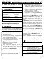
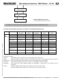
1. S
PECIFICATION
MULTImate
Order Number
# 8 2094
Power supply 4 x AA cells
Idle current when
switched off
0.00035 A
Dimensions (L x W x H) approx. 206 x 75 x 40 mm
Weight incl. batteries approx. 200 g
2. S
AFETY
N
OTES
! Read right through these instructions before use
! Use only for the intended purposes (
3.)
3. A
PPLICATION
The MULTImate is a programming / adjusting device as well as
a servo tester. It is intended exclusively for modelling purposes.
It is prohibited to use the unit for other purposes, e.g. in full-size
aircraft or for industrial applications.
4. S
PECIAL
F
EATURES
• Programming and set-up device for various MULTIPLEX
receivers, speed controllers, sensors and HiTEC /.
MULTIPLEX digital servos.
• Integral servo tester with manual and automatic modes,
pulse width meter.
Many RC components can be adjusted and / or programmed
without the use of a receiver or transmitter.
• Clearly legible, easily understood screen texts with an in-
tuitive menu system; optional German or English language.
• LCD screen offering 2 x 16 characters and automatic
software-controlled contrast adjustment; clearly legible even
in bright conditions.
• Switchable backlighting.
• Ergonomically efficient design:
Symmetrical case layout makes the unit equally easy to use
for left-handed and right-handed persons. Parameters are
selected and activated using a large 3D digi-adjustor (3D =
turn and press), which is easy to operate using the thumb.
• Update capable: via PC port, PC interface lead and the free
MULTImate Updater software.
5. P
OWER
S
UPPLY
/
R
EMOVING THE
B
ATTERY CELLS
The MULTImate is powered by four AA-size rechargeable cells.
These are not included in the set.
It is important to use high-quality rechargeable cells ( 5.2)!
5.1 Inserting the rechargeable cells
a) Open the battery compartment on the underside of the case
Locate the plastic tongue marked with an arrow. Press it
in the direction of the arrow, and remove the battery
com-partment cover.
b) Insert four rechargeable AA cells in the battery
compartment, taking care to maintain correct polarity
Observe the battery symbols in the battery compartment:
“+” = positive terminal, “-” = negative terminal.
c) Replace the battery compartment cover
Locate the plastic tongue of the battery compartment
cover, and fit it in the slot. Carefully press the cover
down until it snaps securely into place.
5.2 Idle current, long-term storage
The idle current of the MULTImate when switched off is 350
micro-Ampère (0.00035 Amp). Even though this value is
extremely low, we recommend that you remove the cells from
the MULTImate if you know you will not be using the unit for a
period of several weeks or more.
The MULTImate should always be used with rechargeable cells
rather than dry cells, as they have to be able to cope with high
peak currents - especially when digital servos are connected to
the device. If the cells in the unit cannot deliver the required
voltage, it will be impossible to address many components (e.g.
the power-on threshold of the MULTIPLEX RX-12-SYNTH DS
IPD receiver is 4.7 Volts). The voltage of the cells in the MULTI-
mate may also be insufficient for some receivers, especially if
the receiver is installed in the model and many servos are
connected to it. In this situation the alternative solution is to use
the receiver battery as the power supply. In this case the
MULTImate detects the receiver battery, and does not switch its
internal power supply on.
6. C
OMPATIBILITY
,
C
ONNECTING
D
EVICES
6.1 Compatibility
Part B of these Operating Instructions includes a list of devices
which can be programmed or adjusted using the MULTImate.
The list of software features and device types which can be con-
nected is constantly updated by means of software updates
( 8.).
6.2 Connecting devices
See Part B of these Operating Instructions.
! When connecting receivers, speed controllers or servos
etc. to the MULTImate, take care to insert the connector
the right way round:
“-” negative (brown), “+” positive (red), “ ” signal (orange).
7. O
PERATING THE
MULTI
MATE
7.1 3D Digi-Adjustor (rotary control / adjustor wheel)
Symbol Function
Brief press
Long press (> 1 second)
If the “long press” option is available, this is
indicated by an “L” at the bottom left-hand
corner of the screen.
Turn to the right (clockwise)
as far as the named menu point

Operating Instructions - MULTImate – V1.42
MULTIPLEX Modellsport GmbH & Co.KG • Westliche Gewerbestraße 1 • D-75015 Bretten (Gölshausen) • www.multiplex-rc.de Seite 2/22
Instructions for MULTImate # 82 5909 (10-05-05/BRAN) • Errors and omissions excepted. •
MULTIPLEX
The 3D digi-adjustor (rotary control / adjustor wheel) on the top
of the MULTImate case can carry out four actions. One or more
functions are assigned to it, depending on the screen display.
These symbols are used in Part B of the instructions to indicate
the functions of the MULTImate.
7.2 Menu navigation
a) Moving between individual menu points
Turn the 3D digi-adjustor to left or right .
b) Calling up a sub-menu
Brief press on the 3D digi-adjustor .
c) Leaving a sub-menu
Turn the 3D digi-adjustor to the far left until the screen
message “Go back …to main menu” / “Zurück …zum
Hauptmenü” appears.
Confirm with a brief press on the 3D digi-adjustor .
7.3 Setting / adjusting values
This is the procedure for setting or adjusting a value or text
displayed on the screen:
a) Activate the value with a brief button-press
The number or text in the second line of the screen
starts flashing.
b) Rotate the 3D digi-adjustor to change the number or text to
the desired value or text ( or )
c) Now press the 3D digi-adjustor once briefly
This concludes Adjust mode.
! Tip: two speeds are available
The effect of slowly turning the 3D digi-adjustor is to change the
displayed value at a low rate. Turning the 3D digi-adjustor
quickly alters the displayed value at ten times the normal speed.
This can be very useful for procedures such as manual servo
testing or servo travel adjustment.
7.4 Holding the 3D digi-adjustor pressed in
Some functions require a long button-press (longer than one
second) in order to confirm a set value, or to avoid a function
being carried out accidentally.
The “long press” option is indicated by a large “L” at the bottom
left-hand corner of the screen.
7.5 Reading out data from the connected device
If certain types of receiver, servo, speed controller etc. are
connected to the MULTImate ( Part B), that device’s data is
read out automatically when you switch from the main menu to
a sub-menu.
If data is not available, or if an error occurs, you will not be able
to switch to the corresponding sub-menu.
7.6 Menu point “Send data” / “Daten senden”
If you wish to change values using the MULTImate and then
transfer them to the connected device (receiver, servo, speed
controller etc.), you must do this via the “Send data” / “Daten
senden” menu point before you leave the sub-menu.
If you quit the menu without using this menu point, the
connected device retains the old settings, and any changes you
have made are lost.
7.7 Menu point “Reset” / “Werkseinst.”
The connected device (receiver, servo, speed controller etc.)
can be returned to the factory default settings (Reset) using the
menu point “Reset” / “Werkseinst.”.
7.8 Detailed list of functions (programming, test, set-up)
For a detailed list of the programming, set-up and test
functionality of the MULTImate please refer to Part B of these
Operating Instructions.
8. S
OFTWAREUPDATE
The MULTImate can be updated via the PC port located at one
end of the unit ( Part B, 2.1).
9. CE
C
ONFORMITY
D
ECLARATION
This device has been assessed and approved in
accordance with European harmonised directives.
This means that you possess a product whose design and
construction fulfil the protective aims of the European
Community designed to ensure the safe operation of
equipment.
If required, you can request MULTIPLEX Modellsport GmbH &
Co.KG to supply a copy of the unit’s Conformity Declaration.
Please contact the company using the contact details at the foot
of the page.
10. G
UARANTEE
/
L
IABILITY
E
XCLUSION
The company MULTIPLEX Modellsport GmbH & Co.KG
accepts no liability of any kind for loss, damage or costs which
are due to the incorrect use and operation of this product, or
which are connected with such operation in any way. Unless the
law expressly states otherwise, the liability on the part of
MULTIPLEX Modellsport GmbH & Co.KG to pay damages,
regardless of the legal argument employed, is limited to the
invoice value of those products supplied by MULTIPLEX
Modellsport GmbH & Co.KG which were directly involved in the
event in which the damage occurred. This does not apply if
liability is incurred according to statutory law on account of
intentional or gross negligence.
We guarantee our products in accordance with the currently
valid statutory regulations. If you wish to make a claim under
guarantee, your initial course of action should always be to
contact the dealer from whom you purchased the equipment.
The guarantee does not cover faults and malfunctions which are
caused by the following:
- Incorrect or incompetent use
- Maintenance carried out incorrectly, belatedly or not at all, or
not carried out by an authorised Service Centre
- Incorrect connections
- The use of accessories other than genuine MULTIPLEX items
- Modifications or repairs which were not carried out by
MULTIPLEX or by an authorised MULTIPLEX Service Centre
- Accidental or intentional damage
- Defects due to normal wear and tear
- Operation of the unit outside the limits stated in the
Specification
- Operation of the unit in conjunction with other makes of
equipment
11. D
ISPOSAL
N
OTES
Electrical equipment marked with the cancelled waste
bin symbol must not be discarded in the standard
household waste; instead it should be taken to a
suitable specialist disposal system.
In the countries of the EU (European Union) electrical
equipment must not be discarded via the normal
domestic refuse system (WEEE - Waste of Electrical and
Electronic Equipment, Directive 2002/96/EG). You can take
unwanted equipment to your nearest local authority waste
collection point or recycling centre. There the equipment will be
disposed of correctly and at no cost to you.
By returning your unwanted equipment you can make an
important contribution to the protection of the environment!

Operating Instructions - MULTImate – V1.42
MULTIPLEX Modellsport GmbH & Co.KG • Westliche Gewerbestraße 1 • D-75015 Bretten (Gölshausen) • www.multiplex-rc.de Seite 3/22
Instructions for MULTImate # 82 5909 (10-05-05/BRAN) • Errors and omissions excepted. •
MULTIPLEX
P
ART
B
D
ETAILED LIST OF THE PROGRAMMING
,
TEST AND SET
-
UP FUNCTIONS
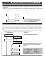
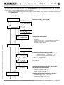
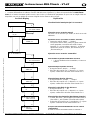
1.
S
WITCHING THE
MULTI
MATE
O
N AND
O
FF
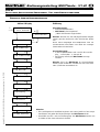
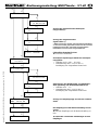
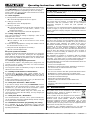
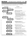
O
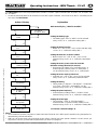
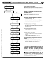
VERVIEW OF THE MAIN MENU LEVELS
Action & Display Explanation
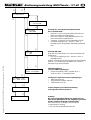
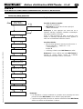
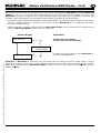
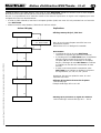
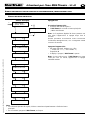
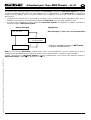
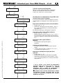
Note:
• In each case the following series of screen-
shots start and end at the main menu level, and
show the screen displays generated by the MULTImate.
•
Please see the screen-shots printed above for details of the MULTImate’s power-
on and
power
-
off procedures.
...MULTImate....
...push short!
...switch off..
L
1 MPX MULTImate
2 RX-SYNTH IPD
3 RX-SYNTH M-PCM
4 RX M-LINK
5 RX run
6 MULTIcont BL
7 MULTIcont SBEC
8 Servo prog.
9 Servo test
10 Impuls meas.
11 MPX Sensors
Power-on procedure:
• twice in succession
• MULTImate is switched on when
“1 MPX MULTImate” appears in the main menu
Note: If you press the 3D digi-
adjustor only once, the
unit switches itself off again after about six seconds.
This defined power-
on procedure eliminates the risk of
accidentally turning the unit on, and thereby drawing
current unnecessarily.
Power-off procedure:
• back to the main menu level until the screen
displays “…Switch off… L” or “…Ausschalten.. L”,
then
• The screen goes dark, and the MULTImate is
switched off.
Note: If you do not use the MULTImate
when switched
on, it automatically switches itself off again after about
1.5 minutes.

Operating Instructions - MULTImate – V1.42
MULTIPLEX Modellsport GmbH & Co.KG • Westliche Gewerbestraße 1 • D-75015 Bretten (Gölshausen) • www.multiplex-rc.de Seite 4/22
Instructions for MULTImate # 82 5909 (10-05-05/BRAN) • Errors and omissions excepted. •
MULTIPLEX
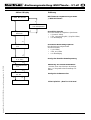
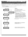
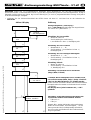
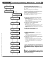
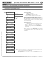
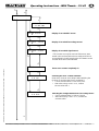
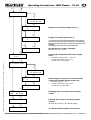
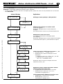
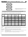
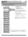
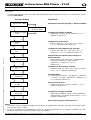
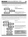
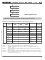
2. M
ENU
1:
MPX
MULTI
MATE
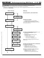
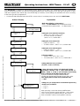
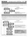
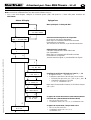
Action & Display Explanation
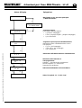
1 Go back
...to main menu
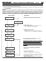
Activating the auto
-
off function:
Press , then turn the rotary control to
select the desired setting.
See Chapter 2.1. “Menu 1-6 PC-com”
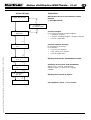
1 MPX MULTImate
1-1 Language
Deutsch
1-2 Illumination
off
1-5 Software
V1.40
1-4 Auto off
on
1-6 PC-Com
1-3 Battery
5.1 V
MULTImate
switched on in main menu
“1 MPX MULTImate”
Display of current power supply voltage
Selecting the backlight options
Here: backlight is switched on.
To switch off:
• (“on” or “ein” flashes)
• until “off” or “aus” flashes
• to confirm
Selecting the language
To switch to the English language:
• (“Deutsch” flashes)
• until “Language English”, (“English” flashes)
• to confirm
Display of current software version

Operating Instructions - MULTImate – V1.42
MULTIPLEX Modellsport GmbH & Co.KG • Westliche Gewerbestraße 1 • D-75015 Bretten (Gölshausen) • www.multiplex-rc.de Seite 5/22
Instructions for MULTImate # 82 5909 (10-05-05/BRAN) • Errors and omissions excepted. •
MULTIPLEX
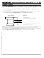
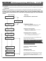
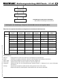
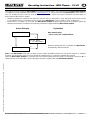
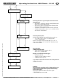
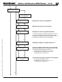
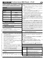
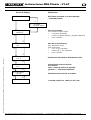
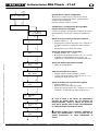
2.1 M
ENU
1-6:
PC-C
OM
This menu is used to update the MULTImate to the latest software version. The software program MULTImate Updater
is available as a free download at the website: www.multiplex-rc.de. This ensures that the MULTImate is future-proof. In
fact, it is already set up to cater for new generations of receivers, servos and speed controllers and other types of
device from the MULTIPLEX stable!
• Obtain the optional PC Interface lead (USB PC lead, # 8 5149, or the serial PC lead, # 8 5150) and connect it to the
PC or laptop and the PC and Data port at one end of the MULTImate. If using a USB-PC lead: install driver.
• Switch the PC or laptop on, and start the MULTImate Updater program. Now transfer the software update by
following the directions included in the operating instructions supplied with the MULTImate Updater.
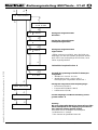
Action & Display Explanation
Note: if the MULTImate starts with an empty screen and the backlight switched on, the device contains no software
program. The most likely cause is an error during the Update process, in which the software was erased.
Open the MULTImate Updater PC program and carry out the Update procedure again, as described in Sections 5.1
starting at Step 4 and also 5.2 of the operating instructions supplied with the MULTImate Updater.
Main menu display
„1-6 PC-Com“ (PC-communication)
1-6 PC-Com
1-6 Ready!
1-6 Go back
...to MULTImate
When the update process is complete, the MULTImate
automatically switches itself off.

Operating Instructions - MULTImate – V1.42
MULTIPLEX Modellsport GmbH & Co.KG • Westliche Gewerbestraße 1 • D-75015 Bretten (Gölshausen) • www.multiplex-rc.de Seite 6/22
Instructions for MULTImate # 82 5909 (10-05-05/BRAN) • Errors and omissions excepted. •
MULTIPLEX
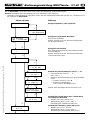
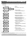
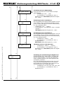
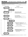
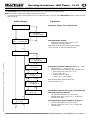
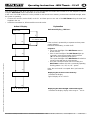
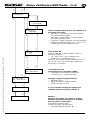
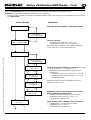
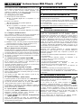
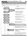
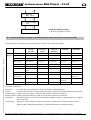
3. M
ENU
2:
RX-S
YNTH
IPD
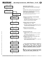
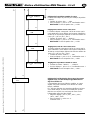
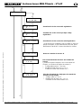
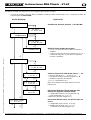
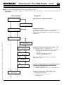
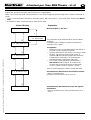
The MULTImate can be used to program MULTIPLEX RX-SYNTH IPD receivers.
Note: The voltage of the power supply must be at least 4.8 V!
• Connect the receiver (socket “B/D”) to the PC and Data port on one end of the MULTImate using the data lead sup-
plied in the set.
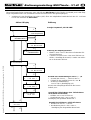
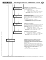
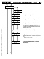
Action & Display Explanation
(…)
(…)
(…)
(…)
2 RX-Synth IPD
2-1 RF-Channel
068
–
35,080 MHz
2-
3 Servo 1
L < FS off >
2-
3 Servo 4
L << 1453 µs
2-
3 Servo 12
not available
2-3 FS length
15.0 sec
2-3 Go back
...to RX IPD
2-4 Hold length
0.5 sec
2 Go back
...to m
ain menu
2-2 Servochannel
7
2-3 Failsafe
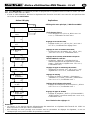
Main menu display “2 RX-Synth IPD”
Display of the set RF channel
(channel cannot be changed).
Note: display after receiver reset:
“RF-Channel Chan. Search” or “HF-Kanal Kanalsuche”
Servo channel display
and / or transmission format of the transmitter in use
(setting cannot be changed).
Note: display after receiver reset:
“Servochannel No signal” or “Servokanäle kein Signal”
Selecting the Fail
-
Safe setting
for servos 1, …, 12
• Select servo 1, …, 12 using or
• Change the fail-safe setting for the selected servo:
• Fail-safe for each servo “on” / “off” or “ein” / “aus”:
• Change fail-safe setting:
and or , confirm with
Note: After receiver reset Fail-Safe is “off” or “aus”
Selecting the Fail
-
Safe period (max. fail
-
safe period
after hold period has elapsed)
• Can be selected from 0.0 sec to 24.0 sec.
• Change value using and or , confirm the
s
e
lected value with

Operating Instructions - MULTImate – V1.42
MULTIPLEX Modellsport GmbH & Co.KG • Westliche Gewerbestraße 1 • D-75015 Bretten (Gölshausen) • www.multiplex-rc.de Seite 7/22
Instructions for MULTImate # 82 5909 (10-05-05/BRAN) • Errors and omissions excepted. •
MULTIPLEX
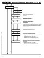
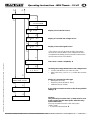
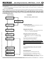
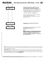
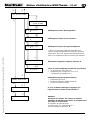
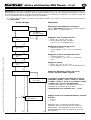
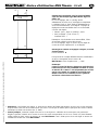
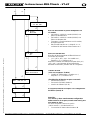
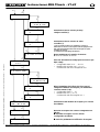
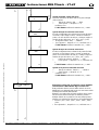
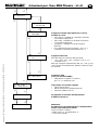
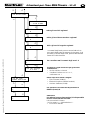
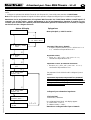
2-5 Error count
2-5 RF errors
0
2-5 Volt. errors
0
2-5 Sgin. errors
0
2-5 Low voltage
4.0 Volt
2-5 Go back
...to RX IPD
2-5 Start errcnt
2.0 sec
2-5 Clear errors
L
Display of recorded RF errors*
Display of recorded low-voltage errors*
Display of recorded signal errors*
* The counter can only be read out if the errors were
stored in the receiver before it was switched off: this is
accomplished by briefly pressing the SET button on the
receiver when errors are indicated.
Erase error counter completely:
Selecting the error counter start time
(how many seconds are to elapse after switching the
receiver on and the start of error recording?):
• Can be selected from 0.2 sec to 24.0 sec.
• Alter value using and or , confirm
the set value with
Selecting the voltage threshold for low voltage e
r
rors
• Can be selected from 3.5 Volt to 5.0 Volt
• Alter value using and or , confirm the
set value with

Operating Instructions - MULTImate – V1.42
MULTIPLEX Modellsport GmbH & Co.KG • Westliche Gewerbestraße 1 • D-75015 Bretten (Gölshausen) • www.multiplex-rc.de Seite 8/22
Instructions for MULTImate # 82 5909 (10-05-05/BRAN) • Errors and omissions excepted. •
MULTIPLEX
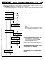
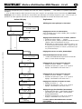
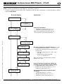
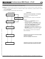
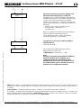
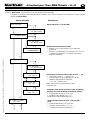
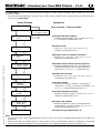
2-6 Options
2-6 Pulse
MPX
-
MPX
2-6 Shift
not available
2-8 RX reset
L
2-7 RX type
RX7 35A V1.21
2-9 Send data
L
2-6 Go back
...to RX IPD
2-6 IPD
on
Selecting the IPD filter
Selecting the IPD filter after switching the receiver on:
• “on” / “off” or “ein” / “aus”, to change, then
or , confirm with
Note: to change the receiver state (IPD “on” / “off” or
“ein” / “aus”) while in use: hold the SET button pressed
in for > two seconds
Selecting the servo signal output format for twelve
-
channel mode
• “MPX-MPX” = MPX 12-channel mode (PPM12) with
MPX servo signal output format
• “MPX-UNI” = MPX 12-channel mode (PPM12) with
UNI servo signal output format
• “Graupner” = Graupner 12-channel mode (PPM24)
• Change format using , then or , confirm the set
transmission format with
If you wish to reset the receiver to the fa
c
tory default
settings (Reset):
Display of connected receiver type
• Description (RX7)
• Frequency band (35 MHz A-band)
• Software version (V1.21)
Caution:
The previously set values and / or data must be sent
to the receiver via this menu point, otherwise they
will not take effect.
The only exception from this is the menu point:
“2-8 RX reset”
• To send the selected data:
Shift switching
(72MHz receivers only)
• Switch shift positive / negative with ,
then or , confirm with

Operating Instructions - MULTImate – V1.42
MULTIPLEX Modellsport GmbH & Co.KG • Westliche Gewerbestraße 1 • D-75015 Bretten (Gölshausen) • www.multiplex-rc.de Seite 9/22
Instructions for MULTImate # 82 5909 (10-05-05/BRAN) • Errors and omissions excepted. •
MULTIPLEX
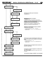
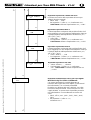
4. M
ENU
3:
RX-S
YNTH
M-PCM
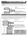
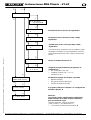
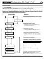
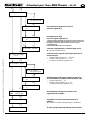
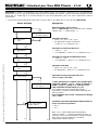
The MULTImate can be used to program any MULTIPLEX RX-SYNTH M-PCM receiver.
Note: the voltage of the power supply must be at least 4.8 V!
• Connect the receiver (socket “B/D”) to the PC and Data port on one end of the MULTImate using the data lead sup-
plied in the set.
Action & Display Explanation
(…)
(…)
(…)
(…)
3 RX-Synth M-PCM
3-
2 Servo 1
L < FS off >
3-
2 Servo 4
L << 1453 µs
3 Go back
...to main menu
3-
2 Servo 12
L << 1500µs >>
3-2 Go back
...to RX M
-
PCM
3-1 RF channel
063
–
35,030 MHz
3-3 Hold length
0.9 sec
3-2 Failsafe
3-2 FS length
16.0 sec
Main menu display “3 RX-Synth M-PCM”
Select
ing the RF channel
• Change the channel using and or ,
confirm the set channel with
Note: After receiver RESET the screen displays
“Chan. Search” or “HF-Kanal Kanalsuche”
Selecting the Fail
-
Safe setting for servos 1, …, 12
• Select servo 1, …, 12 using or
• Change the fail-safe setting for the selected servo:
• Fail-safe for each servo “on” / “off”
or “ein” / “aus”:
• Change fail-safe setting:
and or , confirm with
Note: After receiver reset for all servos:
Fail-safe “off” or “aus”
Selecting the Hold period; applies to all servos
• Can be selected from 0.1 sec to 2.8 sec.
• Change value using and or , confirm the
set value with
Selecting the Fail
-
Safe period (max. fail
-
safe period
after hold period has elapsed)
• Can be selected from 0.0 sec to 20.0 sec.
• Change value using and or , confirm the
selected value with

Operating Instructions - MULTImate – V1.42
MULTIPLEX Modellsport GmbH & Co.KG • Westliche Gewerbestraße 1 • D-75015 Bretten (Gölshausen) • www.multiplex-rc.de Seite 10/22
Instructions for MULTImate # 82 5909 (10-05-05/BRAN) • Errors and omissions excepted. •
MULTIPLEX
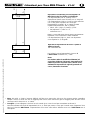
3-4 Error count
3-4 RF error
0
3-4 Volt. err.
0
3-4 Sign. err.
0
3-4 Clear errcnt
L
3-4 Low voltage
4.3 Volt
3-4 Go back
...to RX M
-
PCM
3-6 RX reset
L
3-5 RX type
PCM12 35A V2.68
3-7 Send data
L
Display of recorded RF errors*
Display of recorded low-voltage errors*
Display of recorded signal errors*
Erase error counter completely:
Selecting the voltage threshold for low vol
t
age e
rrors
• Can be selected from 3.0 Volt to 6.9 Volt
• Alter value using and or , confirm the set value
with
Display of connected receiver type
• Description (PCM12)
• Frequency band (35 MHz A-band)
• Software version (V2.68)
If you wish to reset the receiver to the factory d
e
fault
settings:
Caution:
The previously set values and / or data must be sent
to the receiver via this menu point, otherwise they
will not take effect.
The only exception from this is the menu point:
“3-6 RX reset”
• To send the selected data:
* The counter can only be read out if the errors were
stored in the receiver before it was switched off: this is
accomplished by briefly pressing the SET button on the
receiver when errors are indicated.

Operating Instructions - MULTImate – V1.42
MULTIPLEX Modellsport GmbH & Co.KG • Westliche Gewerbestraße 1 • D-75015 Bretten (Gölshausen) • www.multiplex-rc.de Seite 11/22
Instructions for MULTImate # 82 5909 (10-05-05/BRAN) • Errors and omissions excepted. •
MULTIPLEX
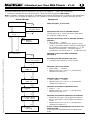
5. M
ENU
4:
RX
M-LINK
Aktion & Display Explanation
This menu point is used when you wish to use the MULTImate to set up a MULTIPLEX RX-DR / DR pro M-
LINK
receiver (does not work with MULTIPLEX RX-light receivers).
•
Use the supplied data lead to connect the receiver (socket marked “B/D”) to the PC and Data port on the end
of the MULTImate.
Changing the receiver name
• Use or to position the v over the character to be
changed.
• Press and use or to select the new character.
confirms the selection, moves on to the next
character to be changed.
(…)
(…)
Sele
cting the fail
-
safe setting for servo 1, … ,16
• Select the servo 1, …, 16 using or
• Fail-safe for the selected servo on / off:
• Change the fail-safe setting:
and or , confirm with
Note: after receiver reset all servos are set to:
Fail-safe “off”
Selecting the fail
-
safe period (max. fail
-
safe time
after the Hold time has elapsed)
• Available range 0.0 sec. to 32.0 sec.
• Change value with and or ,
confirm selected value with
Selecting the Hold period
-
applies to all servos
• Available range 0.0 sec. to 0.76 sec.
• Change value with and or ,
confirm the set value with
4-1 RX Name
7934BE654F
FB
4 Go back
...to main nenu
4 RX M-Link
4-1 v-----------
7934BE654FFB
4-2 Failsafe
4-
2 Servo 1
L < FS off >
4-2 FS length
15.0 sec
4-2 Go back
...to RX M
-
Link
4-2 Ser
vo 16
L < FS off >
4-3 Hold length
0.5 sec
4-1 Go back
...to RX M
-
Link
Main menu display „4 RX M-LINK“

Operating Instructions - MULTImate – V1.42
MULTIPLEX Modellsport GmbH & Co.KG • Westliche Gewerbestraße 1 • D-75015 Bretten (Gölshausen) • www.multiplex-rc.de Seite 12/22
Instructions for MULTImate # 82 5909 (10-05-05/BRAN) • Errors and omissions excepted. •
MULTIPLEX
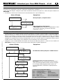
Display of recorded low-voltage errors (*)
Display of recorded signal errors (*)
Erasing the error counter completely:
erases the error counter
* The counter can only be read out if the errors were saved at
the receiver before it was switched off: this is accomplished by
briefly pressing the SET button on the receiver when errors are
indicated.
Des Weiteren muss der Sender ausgeschaltet sein!
Selecting the voltage threshold for low
-
voltage
errors
• Available range 3.0 Volt … 6.9 Volt
• Change value with and or ,
Confirm the set value with
Addressing the screen lines for receiver battery
voltage and downlink channel quality (LQI)
• Available range 0 … 15
• Change value with and or ,
Confirm the set value with
Displaying the receiver type and its software
version
Resetting the receiver to the factory default
settings:
resets the receiver to the default settings.
sends the altered settings to the receiver.
4-4 Zurück
...zu RX M
-
Link
4-4 Error count
4-5 Low voltage
4.0 V
4-6 Sensor addr.
4-6 Addr.voltage
L 0
4-6 Adress LQI
L 1
4-6 Go back
...to RX M
-
Link
4-8 RX reset
L
4-9 Send data
L
4-7 RX Type
RM9 DR V1.00
4-4 Volt. err.
0
4-4 Sign. Err.
0
4-4 Clear errcnt
L

Operating Instructions - MULTImate – V1.42
MULTIPLEX Modellsport GmbH & Co.KG • Westliche Gewerbestraße 1 • D-75015 Bretten (Gölshausen) • www.multiplex-rc.de Seite 13/22
Instructions for MULTImate # 82 5909 (10-05-05/BRAN) • Errors and omissions excepted. •
MULTIPLEX
6. M
ENU
5:
RX
R
UN
This menu point is used when you wish to set a MULTIPLEX RX-SYNTH IPD receiver to a new frequency channel
using the MULTImate, but the SET button is not accessible.
In the case of M-PCM receivers it is also possible to read out the error memory, and measure the field strength, when
the system is operating.
• Connect the receiver (socket “B/D”) to the PC and Data port on one end of the MULTImate using the data lead
supplied in the set.
• Switch the transmitter on; RF transmission must be active.
Action & Display Explanation
Main menu display „5 RX Run“
Displaying the receive
r’s error memory:
activates the display
Typical display: RF:0 U:0 S:63
5 RX run
5-1 IPD Chan.src
5 Go back
...to main menu
5-3 M-PCM Errors
5-4 M-PCM RF-Pow
Displaying the field strength of the aerial signal:
activates the display: display value range 0 ... 100 %
If the receiver is powered by a separate receiver power
supply (battery):
Disconnect the battery, or switch it off!
Sequence
• The screen backlight of the MULTImate starts to
flicker (search)
• If the screen backlight of the MULTImate lights up
constantly, move the transmitter stick four times
( see receiver operating instructions).
The screen backlight of the MULTImate will switch on
and off in time with the stick movements.
• Once the channel has been set successfully, the
MULTImate confirms this with a constantly repeating
flashing pattern: “on / off / on / off – pause”
Note: the set channel is accepted when you leave the
menu.
5-2 IPD Button

Operating Instructions - MULTImate – V1.42
MULTIPLEX Modellsport GmbH & Co.KG • Westliche Gewerbestraße 1 • D-75015 Bretten (Gölshausen) • www.multiplex-rc.de Seite 14/22
Instructions for MULTImate # 82 5909 (10-05-05/BRAN) • Errors and omissions excepted. •
MULTIPLEX
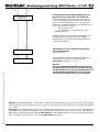
7. M
ENU
6:
MULTI
CONT
BL
A fully charged flight battery is required for programming MULTIcont BL-XX speed controllers (BL-17/II, BL-27/II, BL-
37/II and BL-54).
• Locate the UNI lead attached to the MULTIcont BL-XX speed controller, and connect it to the PC and Data port on
one end of the MULTImate.
Note: The flight battery must be connected and disconnected at the right moment; please refer to the flow chart below.
Caution: Always proceed exactly as described in the instructions, as the MULTImate processes servo signals
when programming MULTIcont BL-XX speed controllers. If you neglect this, the motor could burst into life
unexpectedly (injury hazard)! For safety’s sake you can disconnect one of the three motor wires before starting
the programming procedure.
Action & Display Explanation
Main menu display „6 MULTIcont BL“
automatic
, or
6-4 Send data
Power on!
6-4 Send data
please wait...
6-4 Send data
OK!
6 MULTIcont BL
6-1 Battery mode
LiPo
6-2 Brake
off
6-3 Reverse
off
6-4 Send data
Power off!
6 Go back
...to main menu
Setting the brake function
• Brake “on” / “off” or “ein” / “aus” can be selected using
and or , confirm the setting with
Setting the battery type
• Battery type “LiPo” or “NiXX” is selcted using and
or , confirm the setting with
Setting the direction of motor rotati
on
• Motor reverse “on” / “off” or “ein” / “aus” can be
selected using and or , confirm the setting
with
Connect the flight battery to the speed controller
(voltage on)
When the data transfer is concluded, the screen
automatically switches to: “5-4 Send data --> OK!” or
“5-4 Daten senden --> OK!”
Caution: disconnect battery when finished (voltage off)
The transfer process
The transfer process is automatic; please wait
To prepare for sending the selected data:
switch voltage off (disconnect battery)!
Important! Always set all three possible parameters
- battery mode, brake and motor reverse - as required,
as the menu always starts with default values (the
current settings of the speed controller cannot be read
out)!

Operating Instructions - MULTImate – V1.42
MULTIPLEX Modellsport GmbH & Co.KG • Westliche Gewerbestraße 1 • D-75015 Bretten (Gölshausen) • www.multiplex-rc.de Seite 15/22
Instructions for MULTImate # 82 5909 (10-05-05/BRAN) • Errors and omissions excepted. •
MULTIPLEX
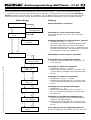
8. M
ENÜ
7:
MULTI
CONT
SBEC
The MULTImate can be used to program MULTIcont BL-XX S-BEC speed controllers (BL-40 S-BEC, BL-55 S-BEC and
BL-70 S-BEC).
• Locate the UNI lead attached to the MULTIcont S-BEC speed controller, and connect it to the PC and Data port on
one end of the MULTImate.
Action & Display Explanation
Main menu display „7 MULTIcont SBEC“
7 MULTIcont SBEC
7-1 Battery mode
LiPo
7-2 Brake
off
7-3 Reverse
off
7-4 Cutoff type
reduce power
7 Go back
...to main menu
7-5 Softstart
on
7-6 Timing
automatic
7-7 Frequency
8 kHz
7-8 Model type
Airplane
7-9 Send data
L
Setting the brake function
• Brake “on” / “off” or “ein” / “aus” can be selected using
and or , confirm the setting with
Setting the battery type
• The battery type “LiPo” or “NiXX” can be selected
using and or , confirm the setting with
Setting the direction of
motor rotation
• Motor reverse “on” / “off” or “ein” / “aus” can be
selected using and or , confirm the parameter
with
Setting the motor power
-
off mode when the
minimum voltage threshold is reached
• Hard power-off “switch off” or “sofortiger Stop” or
reduced power (“reduce power” or “Leist.reduz. ”)
can be selected using and or , confirm with
Setting the model type
• The “Airplane” / “Heli” or „Flächenmodelle” /
“Hubschrauber” (= governor mode) setting can be
selected using and or , confirm the setting with
Setting the motor start
-
up behaviour
• Soft-start “on” / “off” or “ein” / “aus” can be selected
using and or , confirm the parameter with
Setting the timing
• Timing setting “7 degrees” / “30 degrees” / “automatic”
or “7 Grad” / “30 Grad” / “automatisch” can be
selected using and or , confirm the setting with
Setting the pulse frequency
• Pulse frequency setting “8 kHz” / “16 kHz” can be
selected using and or , confirm the setting with
To
send the selected settings:
Notes:
• It is essential to send the set values or data to the MULTIcont BL-XX S-BEC speed controller using menupoint 6-
9,
otherwise they will not take effect.
• After you call up the menu, the unit reads out the values currently set in the speed con
troller. For this reason you
only have to concern yourself with the parameters you wish to re-program.

Operating Instructions - MULTImate – V1.42
MULTIPLEX Modellsport GmbH & Co.KG • Westliche Gewerbestraße 1 • D-75015 Bretten (Gölshausen) • www.multiplex-rc.de Seite 16/22
Instructions for MULTImate # 82 5909 (10-05-05/BRAN) • Errors and omissions excepted. •
MULTIPLEX
9. M
ENU
8:
S
ERVOPROG
.
The MULTImate is suitable for programming HiTEC digital servos which can communicate with the programming
devices HFP10/20 and HPP-21, and also for programming all MULTIPLEX digital servos with digi 4 electronics or later
(with the exception of the POLO digi 4 and TITAN digi 4). However, not all settings are available; this varies according
to the servo type to be programmed.
• Connect the UNI lead attached to the HiTEC servos to the PC and Data port on one end of the MULTImate.
Action & Display Explanation
Main menu display „8 Servoprog.“
After : the MULTImate reads out the data for the
connected servo (“please wait …” or “bitte warten…”)
8-1 Reverse
off
8-2 Deadband
1
8-3 Speed.
64
8-4 Failsafe
off
8-5 Positions
4
8-5 Positions
Send data?
8-5 Go back **
...to Servo
8 Servoprog.
8 Go back
...to main menu
Setting the servo direction (reverse)
• Values: “on” / “off” or “ein” / “aus”
• To set the direction of rotation:
, then or , confirm with
Setting the servo dead
-
zone
• Range of values: 1, …, 16
• To set the value: , then or , confirm with
Setting the servo transit speed
• Range of values: 1, …, 64
•
To set the value:
, then
or
, confirm with
Fail
-
Safe settings
• Values: “on” / “off” or “ein” / “aus”
• To set the value: , then or , confirm with
Setting: Do you really want to overwrite the prev
i
ously
stored servo positions?
• If no:
• If yes:
** Note: this menu point is only displayed if all the
parameters (“middle”, “end 1”, “end 2” and “failsafe” or
“Mitte”, “Endp. 1”, “Endp. 2” and “Failsafe”) have already
been confirmed by the MULTImate with “ok”.
If you do not wish to change individual values:
Confirm the appropriate parameter in turn with twice.
The display must confirm each parameter with
“
--
> OK!
”
Setting different servo positions
(Travels / Centre / Fail-Safe)
Note: pressing sends the already modified data -
such as servo reverse, transit speed etc. - to the servo.
This is necessary for software reasons; the servo is
then re-started in order to set its position correctly.

Operating Instructions - MULTImate – V1.42
MULTIPLEX Modellsport GmbH & Co.KG • Westliche Gewerbestraße 1 • D-75015 Bretten (Gölshausen) • www.multiplex-rc.de Seite 17/22
Instructions for MULTImate # 82 5909 (10-05-05/BRAN) • Errors and omissions excepted. •
MULTIPLEX
**
Setting load reduction for digital servos with
MULTIPLEX digi 5 or HiTEC G2 electronics
This parameter defines the extent to which a digital
servo gives way after a certain time delay when under
excessive load.
Example: 20% load reduction means that the servo
only delivers 80% of full power when the time delay has
elapsed. This effectively prevents an overload situation
for the servo and / or the power supply.
• Value range: “off” or “aus”, “10%”, “20%”, “30%”,
“40%”, “50%”
• To set: , then or , confirm with
8-5 Set middle
0
8-5 Set end 1
290
8-5 Set failsafe
0
8-5 Set end 2
-
290
8-6 Load reduce
off
Setting the servo centre position
Mechanical position of the servo output device for
1500µS (neutral signal)
• Range of values -290, …, +290
• To set the value: , then or , confirm with
. MULTImate confirms the input with “--> OK!”
Setting servo end
-
point 1
The set value corresponds to the end-point to which the
servo runs when it is fed a signal length of 900µs or
2100µs (according to the servo direction “on” / “off” or
“ein” / “aus”).
• Range of values: 290, …, +3000***
• To set the value: , then or , confirm with .
MULTImate confirms the input with “--> OK!”
Setting servo end
-
point 2
The set value corresponds to the end-point to which the
servo runs when it is fed a signal length of 900µs or
2100µs (according to the servo direction “on” / “off” or
“ein” / “aus”).
• Range of values: -3000***, …, -290
• To set the value: , then or , confirm with .
MULTImate confirms the input with “--> OK!”
Setting the servo fail
-
safe position
• Range of values: -3000***, …, + 3000***
• To set the value: , then or , confirm with .
MULTImate confirms the input with “--> OK!”

Operating Instructions - MULTImate – V1.42
MULTIPLEX Modellsport GmbH & Co.KG • Westliche Gewerbestraße 1 • D-75015 Bretten (Gölshausen) • www.multiplex-rc.de Seite 18/22
Instructions for MULTImate # 82 5909 (10-05-05/BRAN) • Errors and omissions excepted. •
MULTIPLEX
Setting the resolution for digital servos with
MULTIPLEX digi 5 or HiTEC G2 electronics
If you set “low” or "niedrig" the full servo travel of +/-
90° is available. The “high” or “hoch" setting prod uces
maximum servo travel of +/- 60°. In this case the
range for centre offset is +/-8°, i.e. only half as great.
• Values: “low” / “high” or “niedrig“ / “hoch“
• To set: , then or , confirm with
Notes: if you change servo resolution, you will also
need to re-adjust the servo travel.
If you set “high” or “hoch“, do not set servo travels
greater than +/- 60°.
• Note: ***The range of values +/- 3000 lies outside the mechanical limits of the servo. For th
is reason when turning
the knob always watch the servo to ensure that it does not strike its mechanical end-stops (for most servos the end-
stop is located around +/- 1900).
• Practical tip: “How can I couple two servos to one channel (e.g. using two servos to actuate one control surface)?”
At the transmitter leave the servo centre and the servo travel settings for the corresponding channel at 0% and +/-
100%. Now adjust the two servos using the MULTImate
. It is not a good idea to adjust one servo using the
transmitter, and the second servo using the MULTImate!
8-8 Reset
L
8-9 Send data
L
8-7 Resolution
high
To accept the changes you have made permanently
and store them in the servo:
MULTImate confirms with “--> OK”
Note:
With the exception of 7-8 (default settings) all the
parameter changes you have made must be sent
to the servo using this menu point. The servo
does not accept the data otherwise, i.e. it remains
in its previous state.
Set the servo to the default values (Reset)
To select:

Operating Instructions - MULTImate – V1.42
MULTIPLEX Modellsport GmbH & Co.KG • Westliche Gewerbestraße 1 • D-75015 Bretten (Gölshausen) • www.multiplex-rc.de Seite 19/22
Instructions for MULTImate # 82 5909 (10-05-05/BRAN) • Errors and omissions excepted. •
MULTIPLEX
10. M
ENU
9:
S
ERVOTEST
Servo signal generator for adjusting and testing servos, speed controllers etc., without transmitter and receiving system.
• Connect the UNI lead attached to the servo to the PC and Data port on one end of the MULTImate.
Note: In “Servo test” mode you may notice the screen display and the screen backlight flickering slightly. This is not a
fault in the device; it simply reflects the irregular current drain of the servo motor.
Action & Display Explanation
Main menu display „9 Servotest“
9-1 Manual
0 µs
9 Go back
...to main menu
9-2 Max. right
1550 µs
9-2 Speed
5
9-2 Servo move
like stick
9-2 Servo
running...
9-2 Go back
...to servotest
9-1 Manual
1500 µs
9-2 Max. left
1450 µs
9 Servotest
9
-
2 Automatic
Setting the servo in manual mode
When the display shows 0 µs the servo is “soft”, i.e. it
receives no control signal
Setting the left servo end
-
point
• Range of values: 900µS, …, 1450µS
• Activate the menu point using , then or for
setting the value, confirm the set value with
Setting the type of simulation (rotary movement)
• Control “like stick” / “wie Knüppel” (smooth movement)
or “like switch” / “wie Schalter” (abrupt movement)
• Activate the menu point using , then or to set the
value. Confirm the set value with
Setting the servo in “Automatic” mode
Setting the servo transit speed
• Range of values: 5, …, 40
• Activate the menu point using , then or for
setting the value, confirm the set value with
Setting the right servo end
-
point
• Range of values: 1550µS, …, 2100µS
• Activate the menu point using , then or for
setting the value, confirm the set value with
Servo immediately runs to the set values
The servo automatically moves from left to right
Setting (moving) the servo in “Manual” mode
• Range of values: 900µs, …, 2100µS
• When the value “1500µs” (servo centre setting)
flashes, this signal length is passed to the servo.
Change the signal length (pulse width) using or ,
conclude the manual servo test with . After
conclusion the screen again displays: “8-1 Manual 0
µs” or “8
-
1 Manuell 0 µs”
Concluding the automatic servo test
• concludes the automatic test process, i.e. the
servo stops running

Operating Instructions - MULTImate – V1.42
MULTIPLEX Modellsport GmbH & Co.KG • Westliche Gewerbestraße 1 • D-75015 Bretten (Gölshausen) • www.multiplex-rc.de Seite 20/22
Instructions for MULTImate # 82 5909 (10-05-05/BRAN) • Errors and omissions excepted. •
MULTIPLEX
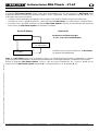
11.
M
ENÜ
10
I
MPULSE MEAS
.
Action & Display Explanation
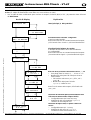
12.
M
ENU
11:
MPX
SENSORS
This menu is designed for configuring and setting up M-LINK sensors, and reading out the sensor values. The sensor
addresses for measured value and options can be assigned to specific lines on the transmitter’s integral screen. Please
note that each address can only be assigned once, i.e. if there is an ‘address clash’ only one of the values is displayed.
This is explained here using as an example the configuration of the temperature sensor with its two measurement
channels. All M-LINK sensors are set up using the same method; the only difference is that not all of them have two
measurement channels.
• Connect the UNI lead (marked RX/S) attached to the M-LINK sensor to the PC and Data port at the end of the
MULTImate. Note that the sensor must not be connected to any other devices at this stage!
Action & display Explanation
When the transmitter is switched on, this menu can be used to read out the pulse width at each receiver output
(channel), i.e. the signal which is otherwise used to control the components (servos, speed controllers etc.) con
nected
to the individual servo channels.
Connect the receiver output to be measured to the PC and Data port on one end of the MULTImate
, using the data
lead supplied in the set.
Switch the receiver on (receiver must be connected to a receiver battery for power).
Main menu display “10 Impulse meas.”
(Signal Measure)
10 Impulse meas.
10-1 Impule len
1452 µs
10 Go back
...to main menu
Signal length display
The signal length is displayed on the screen of the
MULTImate, corresponding to the position of the
transmitter stick (switch, slider etc.)
(…)
(…)
(…)
(…)
Displaying the values for the connected sensor
Measured values and set option values for the sensor
connected to the MULTImate can be displayed by
turning the rotary control on the unit.
This example shows the temperature of channel 1 of
the temperature sensor, with the default address 4.*
11-1 Adress 0
no sensor
11-1 Adress 4
22.1°C
11-1 Adress 15
no sensor
11-1 Go back
to
Sensors
*
Factory default sensor addresses:
Addr 1: U receiver voltage Receiver
Addr 2: LQI downlink channel quality Receiver
Addr 3: U1 voltage, channel 1 Voltage sensor
Addr 4: T1 temperature, channel 1 Temperature sensor
Addr 5: RPM (mag / opt) Rev-count sensor
Addr 6: Altitude Vario / altitude sensor
Addr 7: Climb rate Vario / altitude sensor
Addr 8 Addr 15 no default assignments!
Main menu display “11 MPX sensors”
11 MPX Sensors
11-1 Sens. value
11 Go back
...to main menu
Page is loading ...
Page is loading ...
Page is loading ...
Page is loading ...
Page is loading ...
Page is loading ...
Page is loading ...
Page is loading ...
Page is loading ...
Page is loading ...
Page is loading ...
Page is loading ...
Page is loading ...
Page is loading ...
Page is loading ...
Page is loading ...
Page is loading ...
Page is loading ...
Page is loading ...
Page is loading ...
Page is loading ...
Page is loading ...
Page is loading ...
Page is loading ...
Page is loading ...
Page is loading ...
Page is loading ...
Page is loading ...
Page is loading ...
Page is loading ...
Page is loading ...
Page is loading ...
Page is loading ...
Page is loading ...
Page is loading ...
Page is loading ...
Page is loading ...
Page is loading ...
Page is loading ...
Page is loading ...
Page is loading ...
Page is loading ...
Page is loading ...
Page is loading ...
Page is loading ...
Page is loading ...
Page is loading ...
Page is loading ...
Page is loading ...
Page is loading ...
Page is loading ...
Page is loading ...
Page is loading ...
Page is loading ...
Page is loading ...
Page is loading ...
Page is loading ...
Page is loading ...
Page is loading ...
Page is loading ...
Page is loading ...
Page is loading ...
Page is loading ...
Page is loading ...
Page is loading ...
Page is loading ...
Page is loading ...
Page is loading ...
-
 1
1
-
 2
2
-
 3
3
-
 4
4
-
 5
5
-
 6
6
-
 7
7
-
 8
8
-
 9
9
-
 10
10
-
 11
11
-
 12
12
-
 13
13
-
 14
14
-
 15
15
-
 16
16
-
 17
17
-
 18
18
-
 19
19
-
 20
20
-
 21
21
-
 22
22
-
 23
23
-
 24
24
-
 25
25
-
 26
26
-
 27
27
-
 28
28
-
 29
29
-
 30
30
-
 31
31
-
 32
32
-
 33
33
-
 34
34
-
 35
35
-
 36
36
-
 37
37
-
 38
38
-
 39
39
-
 40
40
-
 41
41
-
 42
42
-
 43
43
-
 44
44
-
 45
45
-
 46
46
-
 47
47
-
 48
48
-
 49
49
-
 50
50
-
 51
51
-
 52
52
-
 53
53
-
 54
54
-
 55
55
-
 56
56
-
 57
57
-
 58
58
-
 59
59
-
 60
60
-
 61
61
-
 62
62
-
 63
63
-
 64
64
-
 65
65
-
 66
66
-
 67
67
-
 68
68
-
 69
69
-
 70
70
-
 71
71
-
 72
72
-
 73
73
-
 74
74
-
 75
75
-
 76
76
-
 77
77
-
 78
78
-
 79
79
-
 80
80
-
 81
81
-
 82
82
-
 83
83
-
 84
84
-
 85
85
-
 86
86
-
 87
87
-
 88
88
-
 89
89
-
 90
90
-
 91
91
-
 92
92
-
 93
93
-
 94
94
-
 95
95
-
 96
96
-
 97
97
-
 98
98
-
 99
99
-
 100
100
-
 101
101
-
 102
102
-
 103
103
-
 104
104
-
 105
105
-
 106
106
-
 107
107
-
 108
108
-
 109
109
-
 110
110
-
 111
111


MULTIPLEX Multimate Owner's manual
- Type
- Owner's manual
- This manual is also suitable for
Ask a question and I''ll find the answer in the document
Finding information in a document is now easier with AI
in other languages
Related papers
-
MULTIPLEX RX-7 User manual
-
-
-
-
-
-
MULTIPLEX RX-7-DR Owner's manual
-
-
-
Other documents
-
HiTEC ePowerbox 17A Owner's manual
-
-
 Multiplex Technology COCKPIT SX Operating instructions
-
-
-
 Hitec RCD Inc. HRC32125S Owner's manual
-
-
-
-

