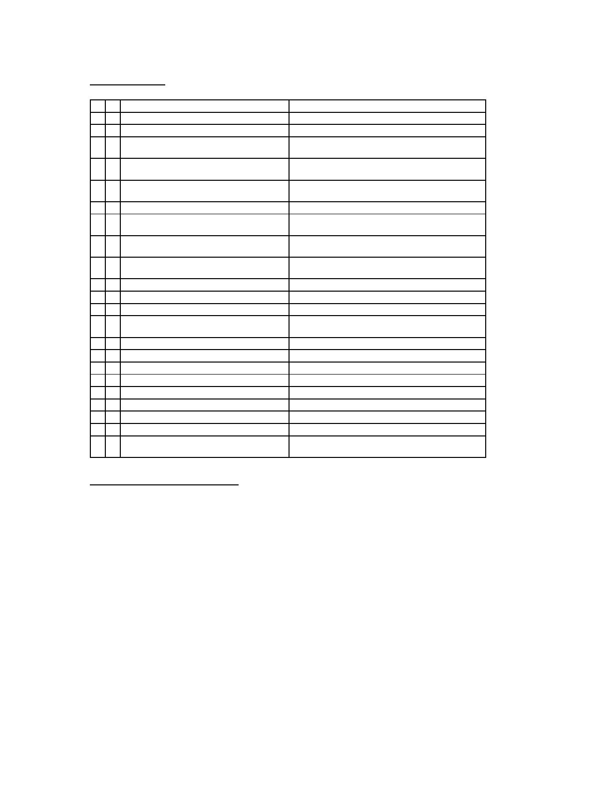
1
N4i Installation Manual
(picture of N4i screen)
2
Table of Contents
N4i Computer Parts List.................................................................................................. 4
Netpulse Stabilizer Bar Parts List................................................................................... 6
Hardware List................................................................................................................... 7
Tools Needed for Installation........................................................................................... 7
N4i Assembly Instructions ............................................................................................... 8
Wiring the N4i Station.................................................................................................... 10
N4i Final Assembly......................................................................................................... 12
Install Stabilizer Bar....................................................................................................... 20
PC Configuration Instructions...................................................................................... 24
Quick Test Procedures:.................................................................................................. 27
3
N4i Stand Parts List
Lower Floor Stand Vertical Tube Upper Floor Stand Vertical Tube
Floor Stand Base Weldment Floor Stand Base Feet (2)
Base End Cap (2) Power Supply Bracket
4
Floor Stand Base Cover Base Cable Chase Extrusion (2) & Base
Cable Chase Cover (2)
N4i Computer Parts List
N4i Computer Computer Rear Shield
Computer Power Cable Computer Power Extender Cable
5
TV Coax Cable Cat5 Cable (wired installs only)
Wireless Adapter and USB Cable Computer Rear Bracket
(wireless installs only)
Computer Mount Adapter Plate and Tilt Box
6
Netpulse Stabilizer Bar Parts List
Stabilizer Bars (1 long, 1 short) Stabilizer Bracket
Velcro Straps (2) Rubber Sleeves
7
Hardware List
NETPULSE STAND ASSEMBLY
4 1/4-20 x 7/8" Socket Head Screw
Feet to Floor Stand Base Cover
4 1/4-20 x 5/8" Socket Head Screw
Base End Cap / Base Cable Chase Extrusion
2 1/4-20 x 1 1/8 Socket Head Screw
Floor Stand Base Cover front to Floor Stand Base
Weldment
2 1/4-20 x 1 3/8 Socket Head Screw
Floor Stand Base Cover rear to Floor Stand Base
Weldment
2 8-32 x 7/16 Phillip Head Self Tapping Screw
Floor Stand Base Cover to Floor Stand Base
Weldment
3 5mm x 8mm Socket Set Screw
Lower Floor Stand Vertical Tube
2 1/4-20 x 1/2 Pan Head Machine Screw
Lower Floor Stand Vertical Tube to Base Weldment
2 1/4-20 x 1/2 Pan Head Machine Screw
Lower Floor Stand Vertical Tube to Upper Floor Stand
Vertical Tube
2 1/4-20 x 1/4 Pan Head Machine Screw
Computer Mount Adapter Plate and Tilt Box to Upper
Floor Stand Vertical Tube
Netpulse N4i Computer Assembly
4 8/32 x 5/8 Phillips Head Screw
N4i Computer to Computer Rear Bracket and
Computer Mount Adapter Plate and Tilt box
2 5/32 x 1 3/8 Phillips Head Screw
Computer Rear Shield to Computer Rear Bracket
4 1/4-20 x 1/2 Socket Head Screw
Computer Mount Adapter Plate and Tilt box
Netpulse Stabilizer Bar Assembly
4 1/4-20 x 1 3/8 Socket Head Screw
Stabilizer bar
4 1/4" Flat Washer
Stabilizer bar
4 1/4-20 Hex Nut
Stabilizer bar
1 1/4-20 x 1/4 Pan Head Machine Screw
Stabilizer Bracket to Lower Floor Stand Vertical Tube
Tools Needed for Installation
PC Keyboard (PS/2)
Hand Tools:
- Allen Wrench (7/32 and 3/32 drive)
- Phillips head screwdriver
- Crescent wrench or 7/16” open end wrench
8
N4i Assembly Instructions
Follow these steps to assemble N4i Station:
1). Determine the width of the two Floor Stand Base Feet relative to the cardio equipment
base, as shown. Attach the two Floor Stand Base Feet to Floor Stand Base Weldment
using four Socket Head Screws (1/4-20 x 7/8).
9
2). Attach the Base Cable Chase Extrusion to both sides of the Floor Stand Base
Weldment and secure with two Socket Head Screws (1/4-20 x 5/8), as shown.
3). Slide the Power Supply Bracket over the base weldment tube of the Floor Stand Base
Weldment, as shown.
4). Slide the Lower Floor Stand Vertical Tube onto the Floor Stand Base Weldment tube
and align the cables access holes, as shown. Insert and hand-tighten two Pan Head
Machine screws (1/4-20 x ½), but do not tighten at this time.
10
5). Place stand in front of cardio equipment and insert the Upper Floor Stand Vertical
Tube into the Lower Floor Stand Vertical Tube.
Wiring the N4i Station
1). Connect the Computer Power Cable to Computer Power Extender Cable, as shown.
Feed Computer Power extender Cable down the top of the Upper Floor Stand Vertical
11
Tube until it emerges from the cable access hole at the bottom of the Lower Floor Stand
Vertical Tube, as shown.
2). In the same way, feed TV Coax Cable and Cat5 Cable (for wired stations only) down
Upper Floor Stand Vertical Tube. Leave 8-10 inches of all three cables (coax, cat5, and
power) exposed at the top of Upper Floor Stand Vertical Tube.
3). Feed upper ends of cables through Computer Rear Shield as shown in picture above.
Slide the Computer Rear Shield all the way down the Floor Stand Vertical Tube for now
to keep it out of the way until you are to attach in a later step.
12
4). Attach Computer Power Cable to Computer Power Extender Cable, as shown.
N4i Final Assembly
1). Assemble Computer Mount Adapter Plate to Tilt box using the four Socket Head
Screws (1/4-20 x ½). Completed assembly is shown above.
13
2). Attach Computer Rear Bracket to back of N4i Computer as shown above. Attach
computer mount/tilt box assembly you assembled in step 1 to the Computer Rear Bracket
and secure with four Phillips head screws (8/32 x 5/8).
3). Slide computer mount/tilt box assembly onto Upper Floor Stand Vertical Tube and
route cables (power, coax, catt5) out the bottom as shown in picture above. Secure with
two Pan Head Machine screws (1/4-20 x ¼).
14
4). Connect the TV Coax Cable, Cat5 Cable, (for wired stations only), and Computer
Power Cable to the connections on the back of N4i Computer.
5). Adjust the height of the N4i screen by sliding the Upper Floor Stand Vertical Tube up
or down to the desired location and securing with two Pan Head Machine screws (1/4-20
x ½).
15
6). Adjust screen to appropriate viewing angle by first loosening the Socket Head Screws
on the computer mount/tilt box assembly and then tightening in place.
7). For wired installs, skip to step 13. For wireless installs attach a piece of Velcro on the
inside of Computer Rear Shield, as shown.
16
8). Attach another piece of Velcro to Wireless Adapter.
9). Feed USB Cable through bottom hole of computer mount bracket/tilt box assembly
and plug USB cable into either USB port on back of N4i Computer. (It doesn’t matter
which USB port you use).
10). Attach wireless adapter to inside of Computer Rear Shield (using Velcro attached
earlier). Place antenna through hole as shown in picture above. Slide Computer Rear
Shield up the Floor Stand Vertical Tube and plug the free end of the USB Cable into the
Wireless Adapter.
17
12). Coil up any access USB Cable inside the Computer rear Shield and then secure
Computer Rear Shield to Computer Rear Bracket using two Phillips head screws (5/32 x
1 3/8). Skip to step 15.
13). For wired installs, slide Computer Rear Shield up the Floor Stand Vertical Tube and
secure to Computer Rear Bracket using two Phillips head screws (5/32 x 1 3/8).
18
14). Insert four Socket Set Screws (5mm x 8mm) into Lower Vertical Tube (3) and
computer mount/tilt box assembly (1) then tighten.
15). Place power supply at base of Floor Stand Base Cover as shown above. Wrap excess
cable around bottom of Floor Stand Base Weldment tube so power supply and cables can
be cover by Floor Stand Base Cover.
16). Feed cables through Base Cable Chase Extrusion (feed through the side closest to
cable sources).
17). Connect cables (coax, power, cat5 if wired install) to their respective sources.
19
18). Place the Base End Cap on the Floor Stand Base Cover as shown above (this end
will not have cables fed through). Secure with two Socket Head Screws (1/4-20 x 5/8).
19). Install Base Cable Chase Cover into slot on top of Base Cable Chase Extrusion.
Repeat for each side.
20
20). Attach Floor Stand Base Cover and secure with four Socket Head Screws (1/4-20 x 1
1/8 and 1/4-20 x 1 3/8) and Phillips Head Self Tapping Screws (8-32 x 7/16).
Install Stabilizer Bar
1). Determine correct length of the stabilizer required between the Floor Stand Vertical
Tube and the cardio equipment. Slide the long Stabilizer Bar inside the short Stabilizer
Bar to the desired length and insert two socket head screws (1/4-20 x 1 3/8). Secure
screws with flat washers (¼”) and hex nuts (1/4-20).
  • Page 1 1
  • Page 2 2
  • Page 3 3
  • Page 4 4
  • Page 5 5
  • Page 6 6
  • Page 7 7
  • Page 8 8
  • Page 9 9
  • Page 10 10
  • Page 11 11
  • Page 12 12
  • Page 13 13
  • Page 14 14
  • Page 15 15
  • Page 16 16
  • Page 17 17
  • Page 18 18
  • Page 19 19
  • Page 20 20
  • Page 21 21
  • Page 22 22
  • Page 23 23
  • Page 24 24
  • Page 25 25
  • Page 26 26
  • Page 27 27
  • Page 28 28

Ask a question and I''ll find the answer in the document

Finding information in a document is now easier with AI