Öhlins Racing AB
Box 722
S-194 27 Upplands Väsby, Sweden
Phone +46 8 590 025 00
fax +46 8 590 025 80
© Öhlins Racing AB. All rights
reserved. Any reprinting or
unauthorized use without the written
permission of Öhlins Racing AB
is prohibited.
Öhlins products are subject to
continuous improvement and
development, therefore, although
these instructions include the most
up-to-date information available at
the time of printing, minor updates
may occur.
To nd the latest information
contact an Öhlins distributor.
Please contact Öhlins if you have
any questions regarding the
contents in this document.
SETUP DATA
Warning!⚠
Before you ride/drive, always make sure that the
setup is according to the recommended setup
data. Read about adjustments and setting up
in the Öhlins Owner’s Manual before you make
any adjustments. Contact an Öhlins dealer if you
have any questions about setting up.
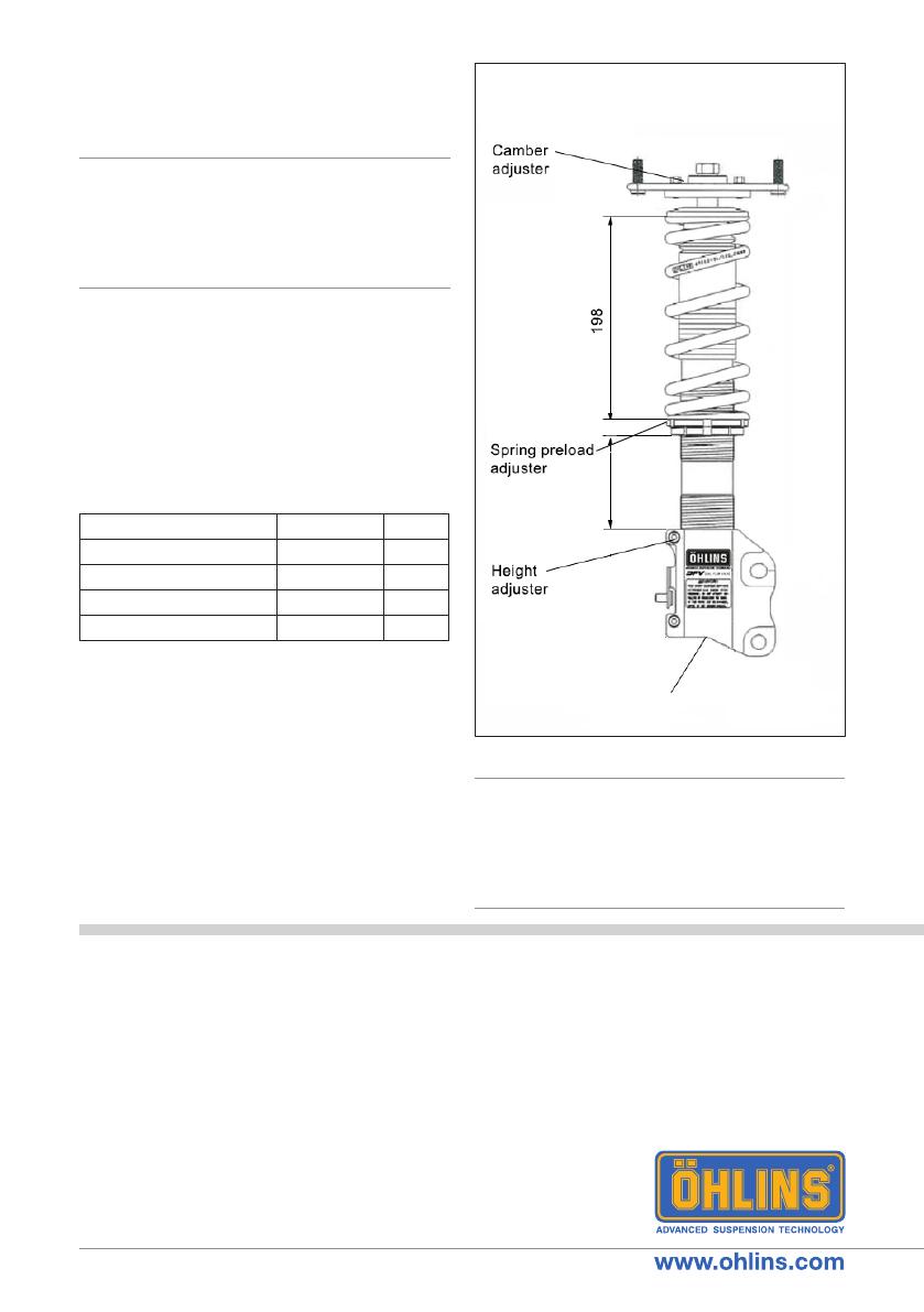
The standard preload is 2 mm from a free
length of 200 mm, giving 198 mm installed
length, see g 3.
ADJUSTMENTS
Part no. MI_MISMI01_0
Issued 2018-12-06
Recommended set-up
Rebound setting
Track 2-7 clicks
Winding road 5-10 clicks
Street 10-20 clicks
Spring preload 2 mm
Recommended spring
48010-31 (100 N/mm)
Vehicle height adjustment range
With both the spring preload and height
adjustments in their recommended positions,
the vehicle is lowered approximately 35 mm
when compared to the original suspension.
The spring preload adjustment range is
2-10 mm. Giving approximately 25-35 mm
lower ride height of the car.
Warning!⚠
The adjustment range is the recommended
position ±10 mm. lf the bracket is moved oulside
the adjustment range, it may come loose or the
wheel might hit the wheel house. As the height
adjuster is turned one rotation, the position
moves 2.0 mm.
93
Fig. 3
Adjustment
knob


