Broan Bottle Warmer WPD29M User manual
- Category
- Cooker hoods
- Type
- User manual
This manual is also suitable for

WPD29M SERIES
INTENDED FOR DOMESTIC COOKING ONLY
INSTALLER: LEAVE THIS MANUAL WITH HOMEOWNER.
HOMEOWNER: USE AND CARE AND OPERATION INFORMATION ON
PAGES 10 AND 11.
V07697 rev. A
HB0059
INSTALLATION INSTRUCTIONS
READ AND SAVE THESE INSTRUCTIONS
!
!
In USA - BEST BY BROAN
®
P.O. Box 140, Hartford, WI 53027
In Canada - BEST BY BROAN
®
550 Lemire Blvd., Drummondville, QC J2C 7W9
For additional information — visit www.bestbybroan.com
SUITABLE FOR USE IN DAMP LOCATIONS WHEN INSTALLED IN A GFCI PROTECTED
BRANCH-CIRCUIT. INTENDED FOR OUTDOOR COVERED PATIO OR LANAI AREA.

WARNING WARNING
- 2 -
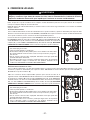
TO REDUCE THE RISK OF FIRE, ELECTRIC
SHOCK OR INJURY TO PERSONS, OBSERVE
THE FOLLOWING:
1. Use this unit only in the manner intended by the
manufacturer. If you have questions, contact the
manufacturer at the address or telephone number
listed in the warranty.
2. Before servicing or cleaning unit, switch power
off at service panel and lock service disconnecting
means to prevent power from being switched on
accidentally. When the service disconnecting
means cannot be locked, securely fasten a prominent
warning device, such as a tag, to the service panel.
3. Installation work and electrical wiring must be
done by qualified personnel in accordance with all
applicable codes and standards, including fire-rated
construction codes and standards.
4. Sufficient air is needed for proper combustion and
exhausting of gases through the flue (chimney) of
fuel burning equipment to prevent backdrafting.
Follow the heating equipment manufacturer’s
guidelines and safety standards such as those
published by the National Fire Protection
Association (NFPA), and the American Society for
Heating, Refrigeration and Air Conditioning
Engineers (ASHRAE), and the local code authorities.
5. When cutting or drilling into wall or ceiling, do not
damage electrical wiring and other hidden utilities.
6. Ducted fans must always be vented to the outdoors.
7. Do not use this unit with any additional solid-state
speed control device.
8. To reduce the risk of fire, use only steel ductwork.
9. This unit must be grounded and protected by a
GFCI.
10. Suitable for use in damp locations only when
installed in a GFCI PROTECTED branch-circuit.
11. This unit is not designed for use with a charcoal
grill.
TO REDUCE THE RISK OF A RANGE TOP GREASE
FIRE:
a) Never leave surface units unattended at high settings.
Boilovers cause smoking and greasy spillovers
that may ignite. Heat oils slowly on low or medium
settings.
b) Always turn hood ON when cooking at high heat or
when flambeing food (Crêpes Suzette, Cherries
Jubilee, Peppercorn Beef Flambé).
c) Clean ventilating fans frequently. Grease should
not be allowed to accumulate on fan or filter.
d) Use proper pan size. Always use cookware appropriate
for the size of the surface element.
TO REDUCE THE RISK OF INJURY TO PERSONS
IN THE EVENT OF A RANGE TOP GREASE
FIRE, OBSERVE THE FOLLOWING*:
1. SMOTHER FLAMES with a close-fitting lid, cookie
sheet or metal tray, then turn off the burner.
BE CAREFUL TO PREVENT BURNS. IF THE
FLAMES DO NOT GO OUT IMMEDIATELY, EVACUATE
AND CALL THE FIRE DEPARTMENT.
2. NEVER PICK UP A FLAMING PAN—You may be
burned.
3. DO NOT USE WATER, including wet dishcloths or
towels—This could cause a violent steam explosion.
4. Use an extinguisher ONLY if:
A. You own a Class ABC extinguisher and you
know how to operate it.
B. The fire is small and contained in the area
where it started.
C. The fire department has been called.
D. You can fight the fire with your back to an exit.
* Based on “Kitchen Fire Safety Tips” published by NFPA.
CAUTION
!
!
1. For general ventilating use only. Do not use to
exhaust hazardous or explosive materials and
vapors.
2. To avoid motor bearing damage and noisy and/or
unbalanced impellers, keep drywall spray,
construction dust, etc. off power unit.
3. Your hood motor has a thermal overload which will
automatically shut off the motor if it becomes
overheated. The motor will restart when it will be
cooled down. If the motor continues to shut off and
restart, have the hood serviced.
4. For best capture of cooking impurities, the bottom
of the hood should be at a minimum of 30” and at
a maximum of 36” above the cooking surface.
5. Two installers are recommended because of the
large size and weight of this hood.
6. To reduce the risk of fire and to properly exhaust
air, be sure to duct air outside—Do not exhaust air
into spaces within walls or ceiling or into attics,
crawl space or garage.
7. This product is equipped with a thermostat which
may start blower automatically. To reduce the risk
of injury and to prevent power from being switched
on accidentally, switch power off at service panel
and lock or tag service panel.
8. To reduce the risk of fire and electric shock, the
Best by Broan WPD29M Series range hood must
be installed with Best by Broan interior blower
model
P12D; Best by Broan exterior blower models
EB12 or EB15; Best by Broan in-line blowers
model ILB11. Other blowers cannot be substituted.
(Blowers sold separately.)
9. Please read specification label on product for
further information and requirements.

HL0084
- 3 -
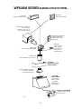
WPD29M
SERIES HOOD
(Canopy with
blower controls
& lighting.
Required for all
installations.)
OPTIONAL
DECORATIVE FLUE
AEWPD SERIES
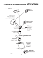
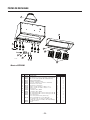
- WPD29M SERIES RANGE HOOD SYSTEM -
Model 410
(10” round duct—2 ft. sections)
MODEL P12D BLOWER
(1200 cfm interior blower,
sold separately.)
Model 418
(10” round adjustable elbow)
Model EB12 (1200 cfm)
or EB15 (1500 cfm)
exterior blower, sold
separately
Model 421
(10” Round vert.
in-line damper)
Recommended
for use with
exterior blowers
Model SV03428 transition
9” x 18” to 10” round
(Included with hood.)
Model ILB11 (1100 cfm)
in-line blower
(includes two 8” x 12” to
10’’ round transitions)
Model 437
(High capacity roof cap)
Model 441
(10” Round wall cap)

- 4 -
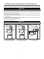
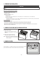
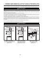
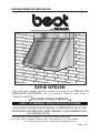
1. PREPARE THE HOOD LOCATION AND SELECT THE INSTALLATION TYPE
This exhaust hood is designed for use with gas or electric outdoor cooking appliances when operated in an outdoor covered
patio or lanai area. As with all electric appliances, this unit should be protected from the effects of weather as much as possible.
Either an interior or exterior blower or in-line blower may be used with this hood. The Best by Broan WPD29M Series must be
installed with blower models P12D, ILB11, EB12 or EB15 only. Other blowers cannot be substituted. (Blowers sold separately.)
Plan where and how the ductwork will be installed.
If installing ILB11 in-line blower, discard its rough-in plate. Refer to instructions packed with in-line blower and follow
steps 1 up to 6, 8, 9, 10, 11, 13 and up of this manual.
Install 10” round galvanized steel ductwork, elbows and roof or wall cap for the type of blower you are installing. Use metal duct
tape to seal duct joints.
The minimum hood distance above cooktop must not be less than 30’’. A maximum of 36” above cooktop is highly
recommended for best capture of cooking impurities.
Distances over 36” are at the installer and users discretion.
Run power cable to installation location.
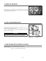
18"
WALL CAP
30" TO 36" ABOVE
COOKING SURFACE
17 11/16" to
TOP OF WOOD
MOUNTING STRIP
HOOD
OPTIONAL DECORATIVE
FLUE or SOFFIT
9" x 18" to 10"
ROUND
TRANSITION
INCLUDED
HH0073A
ROOF CAP
10" ROUND DUCT
10" ROUND ELBOW
EXTERIOR
BLOWER
HH0074A
18"
30" TO 36" ABOVE
COOKING SURFACE
17 11/16" to
TOP OF WOOD
MOUNTING STRIP
HOOD
OPTIONAL DECORATIVE
FLUE or SOFFIT
9" x 18" to 10"
ROUND
TRANSITION
INCLUDED
10" ROUND DUCT
10" ROUND ELBOW
MODEL P12D DUAL INTERIOR
BLOWER TYPICAL DUCTWORK
MODEL EB12 OR EB15 EXTERIOR
BLOWER TYPICAL DUCTWORK
HH0075A
30" TO 36" ABOVE
COOKING SURFACE
HOOD
WALL
CAP
ROOF CAP
IN-LINE BLOWER
10" ROUND DUCT
MODEL ILB11 IN-LINE BLOWER
TYPICAL DUCTWORK
WARNING
This unit is not designed for use with a charcoal grill.
!
WARNING
The power cable must be a GFCI protected branch circuit.
!

Remove the installation kit from inside the hood.
Make sure that the following items are included:
- Wood strip (screwed on back of hood)
- Installation manual
- Transition (9’’ x 18’’ to 10’’ round)
- Accessories including:
• Baffle filters (3)
• Shielded halogen lights (GU10 type base, 120 V, 50 W) (4 for a 42” width hood, 6 for a 54” width hood)
• Bag of parts including:
(3) waterproof wire connectors, (2) wire clamps, (4) flat head screws #10-2’’, (8) screws #8 x 5/8’’, (8) screws #8 x 3/8’’,
(2) wall anchors, (2) washers 3/16’’ ID x 3/4’’ OD
Parts sold separately:
- Interior blower Model P12D.
- In-line blower assembly ILB11, including transitions and rough-in plate. Discard the rough-in plate.
- Exterior blower assembly EB12 or EB15 (all include rough-in plate). Discard the rough-in plate.
- Duct, elbows, dampers, wall and roof caps. Refer to page 3 for a complete list of venting options and model numbers.
- Optional decorative flue AEWPD Series.
- 5 -
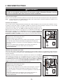
2. PREPARE THE INSTALLATION
CAUTION
When performing installation, servicing or cleaning the unit, it is recommended to wear safety glasses and
gloves.
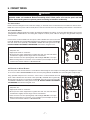
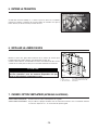
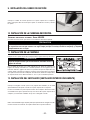
3. REMOVE THE FILTERS AND THE GREASE DRIP RAIL
A. Remove tape on filters.
Remove filters from hood and set aside.
NOTE: It is recommended to start with the
central one.
B. Remove tape on grease drip rail (1).
Lift out grease drip rail and set aside.
NOTE: When tape is removed in the position as
shown at side, drip rail will possibly fall
out due to gravity.
HD0182
1
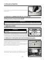
4. REMOVE THE PAN
Using a Phillips no. 2 screwdriver, remove the screws retaining the pan (shaded
part on illustration beside) to the hood. Remove the pan and set aside.
HD0183
RETAINING SCREWS LOCATION

- 6 -
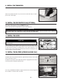
6. INSTALL WOOD MOUNTING STRIP
Measure and mark a level line on wall above cooktop location for the wood
mounting strip (see illustration on page 4).
Center the wood mounting strip over location. See illustration shown at side.
Use #10, 2’’ flat head screws to secure the mounting strip to the drywall.
Make sure to hit the wall studs.
CAUTION
Due to the weight of this hood, ensure that the wood strip is
attached to every available stud, not into the drywall alone.
HD0192A
7. SELECT BLOWER OPTION (EXTERIOR OR INTERIOR)
INTERIOR BLOWER: Follow all subsequent steps of this manual.
EXTERIOR BLOWER: Discard the exterior blower rough-in plate. Refer to instructions packed with exterior blower and follow
steps 8 to 11, 13 and up of the present manual.
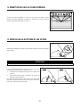
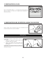
5. REMOVE THE TRANSITION
Using a Phillips no. 2 screwdriver, remove and discard both screws and washers
retaining the transition to the hood. Remove the transition and the wood mounting
strip (on back of hood) and set aside.
R
R
ETAINING
ETAINING
SCREWS
SCREWS
AND
AND
WASHERS
WASHERS
LOCATION
LOCATION
HD0191
1. Drywall
2. Wood mounting strip
3. Flat head screw
4. Wall anchor location
5. Back of hood outline
6. Wall studs

- 7 -
8.2 EXTERIOR OR IN-LINE BLOWER:
Pass the power cable and the exterior or in-line blower cable through the wire clamps in the wiring box and tighten the clamps
to secure the cables. DO NOT REMOVE the wire connector joining BLACK and WHITE wires from wiring box receptacle (A).
Using provided waterproof wire connectors, connect wires as follow: BLACK wire from
power cable to BLACK wire from hood control panel (B), all WHITE wires together (C),
BLACK wire from exterior or in-line blower to ORANGE wire from hood control panel (D),
and GREEN or BARE wires under ground screws (E). DO NOT FORGET TO CONNECT
THE GROUND. Reinstall the wiring box cover.
HE0080
A
B
C
D
E
WATERPROOF WIRE CONNECTORS INSTRUCTIONS:
1. Strip wires 3/8’’.
2. Align frayed strands or conductors.
3. Do not pre-twist. Place stripped wires together with ends even, but lead smaller
stranded wires slightly ahead of larger solid or stranded wire.
4. Twist connector onto wires pushing firmly until hand-tight. DO NOT over torque.
5. When inserting wires into connectors, some sealant may leak out. Wipe off excess
sealant in and around conductors. DO NOT REUSE.
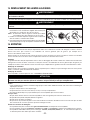
8. CONNECT WIRING
WARNING
Risk of electrical shock. Electrical wiring must be done by qualified personnel in accordance with all
applicable codes and standards. Before connecting wires, switch power off at service panel and lock
service disconnecting means to prevent power from being switched on accidentally.
!
ALL INSTALLATIONS:
Remove the hood wiring box cover. Install wire clamp(s) on back side of the hood. Position the hood below its future location.
NOTE: The hole for the power cable is already done. Punch the other knock-out only if installing exterior blower or in-line blower.
WATERPROOF WIRE CONNECTORS INSTRUCTIONS:
1. Strip wires 3/8’’.
2. Align frayed strands or conductors.
3. Do not pre-twist. Place stripped wires together with ends even, but lead smaller
stranded wires slightly ahead of larger solid or stranded wire.
4. Twist connector onto wires pushing firmly until hand-tight. DO NOT over torque.
5. When inserting wires into connectors, some sealant may leak out. Wipe off excess
sealant in and around conductors. DO NOT REUSE.
Connect wires as follow: BLACK wire from power cable to BLACK wire from hood control
panel (A), all WHITE wires together (B), BLACK wire from wiring box receptacle to ORANGE
wire from hood control panel (C), and GREEN or BARE wire under ground screw (D).
DO NOT FORGET TO CONNECT THE GROUND. Reinstall the wiring box cover.
HE0081
8.1 INTERIOR BLOWER:
Pass the power cable through the wire clamp in the wiring box and tighten the clamp to secure the cable. Discard the wire connector
joining BLACK and WHITE wires from wiring box receptacle. Connect power cable into wiring box using provided waterproof
wire connectors.
POWER CABLE
EXTERIOR OR IN-LINE
BLOWER
CABLE
POWER CABLE
A
B
C
D

- 8 -
12. INSTALL THE BLOWER (INTERIOR BLOWER ONLY)
Assemble barrel nut (packed with blower) approximately halfway onto threaded
stud on top inside of hood.
Lift blower to top inside of hood. Slide blower back to engage blower tab with slot
in hood top and slot in blower with barrel nut.
HD0061
11. INSTALL THE HOOD
Rest the top back cavity of the hood on the wood mounting strip.
Attach transition to 10” round duct. Secure the hood to wood mounting strip with
(5) screws provided at locations shown. Drill (2) 3/16’’ size holes into the drywall
for wall anchors through the existing holes in the inside hood back in the
locations shown. Then, install the two wall anchors with the remaining #8 x 3/4”
screws and the (2) washers provided.
CAUTION
Hold the hood until it is completely secured to the wood
mounting strip.
HD0184
TOP OF HOOD (INSIDE VIEW)
M
OUNTING SCREWS LOCATION
SLOT IN TOP
OF HOOD
BARREL NUT ON
THREADED STUD
DISCHARGE
OPENING
DISCHARGE
OPENING
WALL ANCHORS LOCATION
BACK OF HOOD (INSIDE VIEW)
Use a long, flat-bladed screwdriver to tighten the barrel nut securely. Plug motor
into receptacle, on exterior side of wire box.
HD0054
BLOWER MOTOR
FLAT-BLADED
SCREWDRIVER
BARREL NUT
9. INSTALL THE TRANSITION
Attach the provided transition to top of hood. Use metal duct tape to make all
joints secure and air tight.
HD0057
CAUTION
If this decorative flue is installed in a salt water area (example: coast), rinse all surfaces once a week with
clear water (even if the hood is not used), and wipe dry completely.
10. INSTALL THE DECORATIVE FLUE (OPTIONAL)
OPTIONAL DECORATIVE FLUE AEWPD SERIES
Refer to the instructions included with the optional decorative flue.

- 9 -
Reinstall grease drip rail (1). The illustration beside shows how to reinsert the
grease drip rail into the range hood.
14. REINSTALL GREASE DRIP RAIL AND BAFFLE FILTERS
HD0185
It is recommended to install side filters first and finish with
center one.
1. Insert one end of baffle filter into the upper channel of the
hood.
2. Raise the other end toward the inside of hood and insert
in the grease drip rail of the hood.
Replacement filters are available from your dealer. See label
inside hood for size and part number.
1
HD0189
2
CAUTION
Remove protective plastic film covering baffle filters before installing them.
1
13. REINSTALL THE PAN
Using a Phillips no. 2 screwdriver and the retaining screws, reinstall the pan
(previously removed in step 5) inside the hood (shaded part on illustration
beside).
HD0183
RETAINING SCREWS LOCATION

- 10 -
Grease Drip Rail
The grease drip rail should be cleaned frequently. Lift it out from the hood and use a warm detergent solution. Wash more often
if your cooking style generates greater grease—like frying foods or wok cooking. Allow grease drip rail to dry completely before
reinstalling it in the hood.
Blower Cleaning
Remove the filters in order to access the blower. Vacuum blower to clean. Do not immerse in water. Refer to blower instruction
manual for more details.
Hood Cleaning
Stainless steel cleaning: How to maintain its “BRIGHT LOOK”
Do:
• Regularly wash with clean cloth or rag soaked with warm water and mild soap or liquid dish detergent.
• Always clean in the direction of original polish lines.
• Always rinse well with clear water (2 or 3 times) after cleaning. Wipe dry completely.
• You may also use a specialized household stainless steel cleaner.
Don’t:
• Do not use any steel or stainless steel wool or any other scrapers to remove stubborn dirt.
• Do not use any harsh or abrasive cleansers.
• Do not allow dirt to accumulate.
• Do not let plaster dust or any other construction residues reach the hood. During construction/renovation, cover the hood to
make sure no dust sticks to stainless steel surface.
Avoid: When choosing a detergent
• Any cleaners that contain bleach will attack stainless steel.
• Any products containing: chloride, fluoride, iodide, bromide will deteriorate surfaces rapidly.
• Any combustible products used for cleaning such as acetone, alcohol, ether, benzol, etc., are highly explosive and should
never be used close to a range.
16. USE AND CARE
Baffle Filters
The baffle filters should be cleaned frequently. Use a warm detergent solution. Wash more often if your cooking style generates
greater grease—like frying foods or wok cooking.
Remove filters by pushing them towards the back of hood and rotating filters downward. Baffle filters are dishwasher safe.
Allow filters to dry completely before reinstalling them in the hood.
CAUTION
If this hood is installed in a salt water area (example: coast), rinse all surfaces once a week with clear water
(even if the hood is not used), and wipe dry completely.
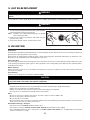
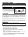
15. LIGHT BULBS REPLACEMENT
This hood must use 120 V, 50 W, MR16 with GU10 base or PAR16 with GU10 base, shielded halogen lamps (included).
WARNING
In order to prevent the risk of personal injury, do not install a lamp identified for use only in enclosed
fixtures.
!
WARNING
In order to prevent the risk of personal injury, the halogen lamps must be cooled down before removing them.
!
1. To remove lamps, gently push upwards and turn counterclockwise
to disengage bulb leads from their grooves.
NOTE: If need be, use a rubber dishwashing glove to add grip
when removing the bulb.
2. Install the new lamps by placing the bulb leads into their
grooves in the socket.
3. Gently push upwards and turn clockwise until secure.
12 3
HO0089

- 11 -
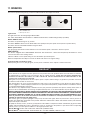
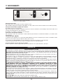
17. OPERATION
The hood is operated using the (3) controls located beneath the front edge of the hood.
1. Light switch
2. Blower ON/OFF switch
3. Blower speed control
Light switch
The light switch turns the halogen lights ON and OFF.
Use 120 V, 50 W, MR16 with GU10 base or PAR16 with GU10 base, shielded halogen lamps (included).
Blower ON/OFF switch
The blower is operated using two (2) controls.
The blower ON/OFF switch turns the blower ON to the speed preset by the speed control (item 3 on picture above).
The blower must be turned ON and OFF using this switch.
Blower speed control
Turn the speed control knob counterclockwise to increase blower speed—clockwise to decrease speed.
HEAT SENTRY
This hood is equipped with a HEAT SENTRY thermostat. This thermostat is a device that will speed up the blower if it senses
excessive heat above the cooking surface.
If blower is ON at a lower speed setting—it turns the blower up to HIGH speed.
When the temperature level drops to normal, the blower will return to its original setting.
Using hood with a covered gas grille
When opening the cover on your gas grille, you may notice a reduction in the capture of smoke and steam.
WARRANTY
BROAN ONE-YEAR LIMITED WARRANTY
Broan warrants to the original consumer purchaser of its products that such products will be free from defects in materials
or workmanship for a period of one year from the date of original purchase. THERE ARE NO OTHER WARRANTIES,
EXPRESS OR IMPLIED, INCLUDING, BUT NOT LIMITED TO, IMPLIED WARRANTIES OR MERCHANTABILITY OR
FITNESS FOR A PARTICULAR PURPOSE.
During this one-year period, Broan will, at its option, repair or replace, without charge, any product or part which is found to
be defective under normal use and service.
This warranty does not cover (a) normal maintenance and service or (b) any products or parts which have been subject to
misuse, negligence, accident, improper maintenance or repair (other than by Broan), faulty installation or installation contrary
to recommended installation instructions.
The duration of any implied warranty is limited to the one-year period as specified for the express warranty. Some states or
provinces do not allow limitation on how long an implied warranty lasts, so the above limitation may not apply to you.
BROAN’S OBLIGATION TO REPAIR OR REPLACE, AT BROAN’S OPTION, SHALL BE THE PURCHASER’S SOLE AND
EXCLUSIVE REMEDY UNDER THIS WARRANTY. BROAN SHALL NOT BE LIABLE FOR INCIDENTAL, CONSEQUENTIAL
OR SPECIAL DAMAGES ARISING OUT OF OR IN CONNECTION WITH PRODUCT USE OR PERFORMANCE. Some
states or provinces do not allow the exclusion or limitation of incidental or consequential damages, so the above
limitation or exclusion may not apply to you.
This warranty gives you specific legal rights, and you may also have other rights, which vary from state to state or province to
another. Any modification performed on this product without the authorization of Broan will void this warranty. This warranty
supersedes all prior warranties.
To qualify for warranty service, you must (a) notify Broan at the address or telephone number stated below, (b) give the model
number and part identification and (c) describe the nature of any defect in the product or part. At the time of requesting
warranty service, you must present evidence of the original purchase date.
Best by Broan
®
, P.O. Box 140, Hartford, WI 53027 USA (1-800-637-1453)
Best by Broan
®
, 550 Lemire Blvd., Drummondville, QC J2C 7W9 CANADA (1-866-737-7770)
HC0014
1
2 3
O

- 12 -
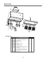
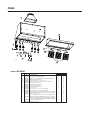
SERVICE PARTS
KEY PART QTY (HOOD WIDTH)
NO. NUMBER DESCRIPTION 42’’ 54’’
1 V03428 T
RANSITION 9” X 18” X 10” ROUND 11
2 V16765 L
AMP SHELL, SOCKET OUTDOOR AND TRIM ASS’Y GU-10 4 6
3 V05921 H
ALOGEN BULBS (50 W, 120 V, PAR16, GU-10) 4 6
4 V06497 T
HERMISTOR HEAT SENTRY 11
5 V06364 R
OTARY SPEED CONTROL 11
6 V03504 B
LOWER SPEED CONTROL KNOB 11
7 V06495 L
IGHT SWITCH 11
8 V06496 B
LOWER SWITCH 11
9
V16939 B
AFFLE FILTERS 8.95” X 8.61” X 1” 2 -
V16940 B
AFFLE FILTERS 14.95” X 8.61” X 1” 1 3
10 V15432 F
ILTER SPRING CLIP 33
11
V16958 G
REASE DRIP RAIL 36”, SS316 1 -
V16964 G
REASE DRIP RAIL 48”, SS316 - 1
12
V16996 I
NSIDE FRAME ASS’Y (42” X 24” X 18”) (INCLUDING ITEM 10) 1 -
V16997 I
NSIDE FRAME ASS’Y (54” X 24” X 18”) (INCLUDING ITEM 10) - 1
* V07697 I
NSTALLATION GUIDE 11
P
ARTS BAG (WATERPROOF WIRE CONNECTOR (3),
* V04216
W
IRE CLAMPS LP16-AP (2), SCREWS #8 X 5/8’’ (8),
11
S
CREWS #8 X 3/8’’ (8), FLAT HEAD SCREW #10 X 2’’ (4),
W
ALL ANCHORS (2), WASHERS 3/16’’ ID X 3/4’’ OD (2))
*V05869 B
EST BY BROAN LOGO 11
* V06933 E
LECTRICAL HARNESS 11
*N
OT SHOWN.
WPD29M MODEL
HL0085
3
2
10
4
1
11
5
6
7
8
9
12

CONÇUE UNIQUEMENT POUR USAGE DOMESTIQUE
INSTALLATEUR : LAISSER CE MANUEL AU PROPRIÉTAIRE.
PROPRIÉTAIRE : DIRECTIVES D’UTILISATION ET D’ENTRETIEN AUX PAGES 22
ET 23.
GUIDE D’INSTALLATION
LIRE ET CONSERVER CES INSTRUCTIONS
!
!
SÉRIE WPD29M
V07697 rév. A
Aux États-Unis — BEST BY BROAN
®
P.O. Box 140, Hartford, WI 53027 USA
Au Canada — BEST BY BROAN
®
550, boul. Lemire, Drummondville (Québec) J2C 7W9 CANADA
Pour obtenir plus d’information, consultez notre site www.bestbybroan.com
HB0059
CONVIENT À UNE INSTALLATION DANS DES LIEUX HUMIDES LORSQU’ELLE EST
RACCORDÉE À UN DISJONCTEUR DE MISE À LA TERRE (DDFT).
C
ONÇUE POUR FONCTIONNER SUR UN PATIO COUVERT OU UNE VÉRANDA.

- 14 -
AVERTISSEMENT AVERTISSEMENT
AFIN DE RÉDUIRE LE RISQUE D’INCENDIE,
D’ÉLECTROCUTION OU DE BLESSURES CORPORELLES,
SUIVEZ LES INSTRUCTIONS SUIVANTES :
1. N’utilisez cet appareil que de la façon prévue par
le manufacturier. Si vous avez des questions,
contactez le manufacturier à l’adresse et au
numéro de téléphone indiqués dans la garantie.
2. Avant de réparer ou de nettoyer l’appareil, coupez
l’alimentation électrique en verrouillant le panneau de
service afin d’éviter sa remise en marche accidentelle.
Si le panneau de service ne peut être verrouillé, y
fixer un avertissement en évidence.
3. Les travaux d’installation et de raccordement
électrique doivent être effectués par du personnel
qualifié, conformément aux codes et aux standards
de construction, incluant ceux concernant le feu.
4. Une quantité d’air adéquate est requise afin d’assurer
une bonne combustion et l’évacuation des gaz par
la cheminée dans le cas des équipements alimentés
au gaz afin de prévenir les retours de cheminée.
Conformez-vous aux instructions et aux standards
de sécurité des manufacturiers d’équipement de
chauffage, tels qu’ils sont publiés par la National
Fire Protection Association (NFPA) et l’American
Society for Heating, Refrigeration and Air
Conditioning Engineers (ASHRAE) ainsi que les
responsables des codes locaux.
5. Lorsque vous coupez ou perforez un mur ou un
plafond, prenez garde de ne pas endommager
les fils électriques ou tout appareil dissimulé.
6. Les ventilateurs avec conduits doivent toujours
évacuer l’air à l’extérieur.
7. Ne pas utiliser cet appareil avec une commande
de vitesse à semi-conducteur additionnelle.
8. Afin de réduire les risques d’incendie, n’utilisez
que des conduits de métal.
9. Cet appareil doit être mis à la terre et protégé par
un DDFT (disjoncteur de fuite à la terre).
10. Convient à une utilisation dans des lieux humides
seulement lorsqu’elle est raccordée à un
DISJONCTEUR DE FUITE À LA TERRE (DDFT).
11. Cet appareil n’est pas conçu pour être utilisé avec
un barbecue.
AFIN DE RÉDUIRE LE RISQUE DE FEU
DE CUISINIÈRE :
a) Ne laissez jamais les appareils de cuisson sans
surveillance lorsqu’ils sont réglés à feu vif.
Les débordements engendrent de la fumée et des
déversements graisseux pouvant s’enflammer.
Chauffez l’huile lentement, à feu doux ou moyen.
b) Mettez toujours la hotte en marche lorsque vous
cuisinez à feu vif ou que vous cuisinez des
mets flambés (crêpes Suzette, cerises jubilé,
steaks au poivre flambé).
c) Nettoyez régulièrement la (les) roue(s) du ventilateur.
Ne laissez pas la graisse s’accumuler sur le
ventilateur ou les filtres.
d) Utilisez le bon format de casserole. Servez-vous
toujours de casseroles et d’ustensiles appropriés à
la dimension de la surface chauffante.
AFIN D’ÉVITER TOUT RISQUE DE BLESSURES
DANS LE CAS D’UN FEU DE CUISINIÈRE, SUIVEZ
CES DIRECTIVES* :
1. Étouffez les flammes avec un couvercle hermétique,
une tôle à biscuits ou un plateau métallique et
ensuite, éteindre le brûleur. PRENEZ SOIN
D’ÉVITER LES BRÛLURES. SI LES FLAMMES
NE S’ÉTEIGNENT PAS IMMÉDIATEMENT,
ÉVACUEZ LES LIEUX ET APPELEZ LES POMPIERS.
2. NE PRENEZ JAMAIS UNE CASSEROLE EN
FLAMMES DANS VOS MAINS. Vous pourriez
vous brûler.
3. N’UTILISEZ PAS D’EAU, incluant linge à vaisselle
ou serviette mouillés; cela pourrait occasionner
une violente explosion de vapeur.
4. N’utilisez un extincteur QUE DANS LE CAS OÙ :
A. Vous savez qu’il s’agit d’un extincteur de classe ABC
et que vous en connaissez le fonctionnement.
B. L’incendie est petit et limité à l’endroit où il a débuté.
C. Les pompiers ont été avisés.
D. Vous pouvez combattre l’incendie en ayant
accès à une sortie de secours.
*Tirées du
Kitchen Fire Safety Tips
publié par la NFPA.
ATTENTION
1. Pour usage domestique seulement. Ne l’utilisez
pas pour évacuer des vapeurs ou des matières
dangereuses ou explosives.
2. Afin d’éviter tout dommage au moteur et de
débalancer ou de rendre bruyante la roue du
moteur, gardez votre appareil à l’abri des poussières
de gypse et de construction/rénovation, etc.
3. Le moteur de votre hotte possède une protection
thermique qui éteindra automatiquement le moteur s’il
devient surchauffé. Le moteur repartira automatiquement
une fois refroidi. Si le moteur continue à arrêter et
à repartir, faites-le vérifier.
4. Pour une meilleure évacuation des odeurs de cuisson,
le bas de votre hotte devrait être situé à un minimum
de 30 po et à un maximum de 36 po au-dessus de
la table de cuisson.
5. Deux installateurs sont recommandés lors de l’installation
vu la grande dimension et le poids de cette hotte.
6. Afin de réduire les risques d’incendie, assurez-vous
d’évacuer l’air à l’extérieur. Ne pas évacuer l’air
dans des espaces restreints comme l’intérieur des
murs ou plafond ou dans le grenier, vide sanitaire
ou garage.
7. Cet appareil est équipé d’un thermostat pouvant
faire démarrer le ventilateur automatiquement.
Afin de réduire le risque de blessures, couper le
courant à partir du panneau électrique et
verrouiller ou apposer un avertissement sur le
panneau afin de prévenir que la hotte soit mise en
marche automatiquement.
8. Afin de réduire les risques d’incendie et d’électrocution,
la hotte Best by Broan de série WPD29M doit être
installée uniquement avec le ventilateur
intérieur Best by Broan P12D; un des ventilateurs
extérieurs Best by Broan suivants : EB12 ou EB15,
ou le ventilateur en ligne Best by Broan ILB11
(vendus séparément). Aucun autre ventilateur ne
doit être utilisé.
9. Veuillez consulter l’autocollant apposé à l’intérieur
de la hotte pour plus d’information ou autres exigences.
!
!

- 15 -
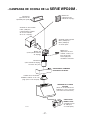
HOTTE SÉRIE
WPD29M
(Avec commandes
ventilateur et
éclairage. Requise
pour toutes
les installations.)
CHEMINÉE DÉCORATIVE
OPTIONNELLE SÉRIE AEWPD
- SYSTÈME DE HOTTE DE CUISINIÈRE SÉRIE WPD29M -
Modèle 437
(Capuchon de toit à haut rendement)
Modèle 441
(Capuchon de toit
de 10 po rond)
Modèle 410
(Conduit de 10 po rond,
sections de 2 pi)
MODÈLE P12D
VENTILATEUR
(Ventilateur intérieur
de 1200 pcm,
vendu séparément)
Modèle 418
(Coude ajustable
de 10 po rond)
HL0084
Modèle SV03428,
transition ronde de
9 po x 18 po à 10 po
(Incluse avec la hotte.)
Modèle 421
(Volet intérieur de
10 po rond vert.)
Recommandé
pour utilisation
avec ventilateurs
extérieurs
Ventilateur extérieur
modèle EB12 (1200 pcm)
ou EB15 (1500 pcm),
vendus séparément
Ventilateur en ligne
modèle ILB11 (1100 pcm)
(incluant deux transitions
rondes de 8 po x 12 po à 10 po)

- 16 -
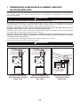
1. PRÉPARER L’EMPLACEMENT DE LA HOTTE ET CHOISIR LE TYPE D’INSTALLATION
Cette hotte de cuisinière a été conçue pour fonctionner avec une cuisinière électrique ou à gaz, lorsqu’elle est utilisée sur un patio
couvert ou une véranda. Comme tous les électroménagers, cet appareil doit, autant que possible, être à l’abri des intempéries.
Cette hotte fonctionne autant avec un ventilateur intérieur, en ligne ou extérieur. La hotte de modèle Best by Broan de série
WPD29M doit être installée uniquement avec l’un des ventilateurs suivants : P12D, ILB11, EB12 ou EB15 (vendus séparément).
Aucun autre ventilateur ne peut être utilisé.
Déterminer à quel endroit et de quelle façon les conduits seront installés.
Si le ventilateur en ligne ILB11 est installé, ne pas utiliser sa plaque ventilateur. Se reporter aux directives incluses
avec celui-ci et suivre les étapes 1 à 6, 8 à 11, 13 et suivantes de ce guide.
Installer des conduits circulaires de 10 po en acier galvanizé, coude(s) et capuchon de mur ou de toit selon le type de ventilateur.
Se servir de ruban adhésif pour conduits en métal pour assurer l’étanchéité des joints.
La distance minimale entre le bas de votre hotte et la surface de cuisson ne doit pas être inférieure à 30 po. Un maximum
de 36 po au-dessus de la surface de cuisson est fortement recommandé pour une meilleure évacuation des odeurs
de cuisson.
Une distance de plus de 36 po demeure à la discrétion de l’installateur et de l’utilisateur.
Passer l’alimentation électrique jusqu’à l’emplacement de l’installation.
18 po
CAPUCHON
DE MUR
DE 30 po À 36 po
AU-DESSUS DE LA
SURFACE DE CUISSON
DISTANCE
DE 17 11/16 po
JUSQU’AU
DESSUS DE LA
LISIÈRE DE BOIS
HOTTE
CHEMINÉE DÉCORATIVE
OPTIONNELLE OU SOFFITE
TRANSITION
RONDE DE
9 po x 18 po à 10 po
(INCLUSE)
HH0073F
CAPUCHON
DE TOIT
CONDUIT ROND
DE 10 po
COUDE ROND DE 10 po
18 po
DE 30 po À 36 po
AU-DESSUS DE LA
SURFACE DE CUISSON
HOTTE
HH0074F
VENTILATEUR
EXTÉRIEUR
DISTA N C E
DE 17 11/16 po
JUSQU’AU
DESSUS DE LA
LISIÈRE DE BOIS
CHEMINÉE DÉCORATIVE
OPTIONNELLE OU SOFFITE
TRANSITION
RONDE DE
9 po x 18 po à 10 p
o
(INCLUSE)
CONDUIT ROND
DE 10 po
COUDE ROND DE 10 po
INSTALLATION TYPIQUE
VENTILATEUR INTÉRIEUR DOUBLE
MODÈLE P12D
INSTALLATION TYPIQUE
VENTILATEUR EXTÉRIEUR
MODÈLE EB12 OU EB15
HH0075F
DE 30 po À 36 po AU-DESSUS
DE LA SURFACE
DE CUISSON
HOTTE
CAPUCHON
DE MUR
CONDUIT ROND
DE 10 po
VENTILATEUR
EN LIGNE
CAPUCHON
DE TOIT
INSTALLATION TYPIQUE
VENTILATEUR EN LIGNE
MODÈLE ILB11
AVERTISSEMENT
Cet appareil n’est pas conçu pour être utilisé avec un barbecue.
!
AVERTISSEMENT
Le fil d’alimentation électrique doit être raccordé à un disjoncteur de fuite à la terre (DDFT).
!

- 17 -
Retirer la trousse d’installation de l’intérieur de la hotte.
S’assurer que les articles suivants sont inclus :
- Lisière de bois
- Guide d’installation
- Transition (9 po x 18 po à 10 po ronde)
- Les accessoires incluant :
• Les filtres à chicanes (3)
• Ampoules halogènes avec écran (20 V, 50 W, avec culot GU10) (4 pour une hotte de 42 po de largeur, 6 pour une hotte
de 54 po de largeur)
• Le sac de pièces incluant :
(3) connecteurs étanches, (2) serre-fils, (4) vis à tête plate n
o
10-2 po, (8) vis n
o
8 x 5/8 po, (8) vis n
o
8 x 3/8 po,
(2) ancrages de gypse, (2) rondelles 3/16 po DI x 3/4 po DE
Pièces vendues séparément :
- Ventilateur intérieur modèle P12D.
- Ensemble de ventilateur en ligne, modèle ILB11, incluant les transitions et la plaque ventilateur. Ne pas utiliser la plaque ventilateur.
- Ensemble de ventilateur extérieur, modèle EB12 ou EB15 (tous incluant la plaque ventilateur). Ne pas utiliser la plaque ventilateur.
- Conduits, coudes, volets, capuchons de mur ou de toit. Consulter la page 15 pour la liste complète des accessoires de
ventilation et les numéros de modèle.
- Cheminée décorative optionnelle série AEWPD.
2. PRÉPARER L’INSTALLATION
ATTENTION
Il est recommandé de porter des lunettes et des gants de sécurité lors de l’installation, de l’entretien ou
de la réparation de cet appareil.
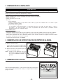
3. RETIRER LES FILTRES ET LA GOUTTIÈRE
A. Enlever le ruban des filtres.
Retirer les filtres de la hotte et les mettre
de côté.
NOTE :Il est recommandé de retirer le filtre
central en premier.
B. Enlever le ruban de la gouttière (1).
Dégager la gouttière de la hotte et la mettre
de côté.
NOTE : Lorsque la hotte est dans la position
démontrée ci-contre et que l’on retire le
ruban, il se peut que la gravité fasse
tomber la gouttière.
HD0182
1
4. RETIRER LE CADRE INTÉRIEUR
À l’aide d’un tournevis Phillips n
o
2, enlever les vis retenant le cadre intérieur
(la pièce colorée en gris dans l’illustration ci-contre) à la hotte. Retirer le cadre
intérieur et le mettre de côté.
HD0183
EMPLACEMENT DES VIS DE RETENUE

- 18 -
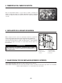
6. INSTALLER LA LISIÈRE DE BOIS
Mesurer et tracer une ligne droite au-dessus de la surface de cuisson pour
l’emplacement de la lisière de bois (voir l’illustration en page 16).
Centrer la lisière de bois, voir l’illustration ci-contre. Fixer la lisière de bois au mur
à l’aide des vis à tête plate n
o
10-2 po en s’assurant d’atteindre les montants.
ATTENTION
Vu le poids élevé de cette hotte, s’assurer que la lisière de bois
soit bien rattachée à tous les montants disponibles. Ne pas
visser la lisière de bois uniquement au mur.
HD0192F
7. CHOISIR L’OPTION VENTILATEUR (EXTÉRIEUR OU INTÉRIEUR)
VENTILATEUR INTÉRIEUR : Suivre toutes les étapes subséquentes de ce guide.
VENTILATEUR EXTÉRIEUR : Ne pas utiliser la plaque ventilateur. Voir les instructions fournies avec le ventilateur extérieur
et suivre les étapes 8 à 11, 13 et suivantes du présent guide.
5. RETIRER LA TRANSITION
À l’aide d’un tournevis Phillips n
o
2, retirer et jeter les deux vis et rondelles
retenant la transition à l’intérieur de la hotte. Retirer la transition ainsi que la
lisière de bois (au dos de la hotte) et mettre de côté.
E
E
MPLACEMENT
MPLACEMENT
DES
DES
VIS
VIS
ET
ET
RONDELLES
RONDELLES
DE
DE
RETENUE
RETENUE
HD0191
1. Mur 4. Localisation des ancrages de gypse
2. Lisière de bois 5. Tracé de l’arrière de la hotte
3. Vis à tête fraisée 6. Montants

- 19 -
8.2 VENTILATEUR EXTÉRIEUR OU EN LIGNE :
Par les serre-fils, insérer le câble d’alimentation électrique et le fil du ventilateur extérieur ou en ligne dans le boîtier électrique
et serrer les serre-fils pour les maintenir en place. NE PAS ENLEVER le connecteur reliant les fils NOIR et BLANC (A) de l’intérieur
du boîtier électrique.
À l’aide des connecteurs étanches fournis, connecter les fils comme suit : le fil NOIR du
câble d’alimentation électrique avec le fil NOIR du panneau de contrôle de la hotte (B),
tous les fils BLANCS ensemble (C), le fil NOIR du ventilateur extérieur ou en ligne avec
le fil ORANGE du panneau de contrôle de la hotte (D), et les fils VERTS ou DÉNUDÉS
sous les vis de mise à la terre (E). NE PAS OUBLIER DE BRANCHER LA MISE À LA
TERRE. Remettre en place le couvercle du boîtier électrique.
HE0080
A
B
C
D
E
DIRECTIVES POUR L’UTILISATION DES CONNECTEURS ÉTANCHES :
1. Dégainer les fils d’une longueur de 3/8 po.
2. Égaliser les brins ou les conducteurs.
3. Ne pas les tordre. Rapprocher les fils et mettre leurs bouts égaux, sauf pour les
fils à brins plus petits, lesquels doivent dépasser légèrement des fils plus gros.
4. Insérer les fils dans le connecteur en poussant légèrement et tordre. NE PAS
trop tordre.
5. Un peu de scellant pourrait s’échapper lors de l’insertion des fils dans un
connecteur. Essuyer l’excès de scellant autour des conducteurs.
NE PAS RÉUTILISER.
8. BRANCHEMENT ÉLECTRIQUE
AVERTISSEMENT
Risque d’électrocution. Le raccordement électrique doit être effectué par du personnel qualifié conformément
aux codes et aux standards. Avant d’effectuer le branchement, coupez l’alimentation électrique au panneau
de service et verrouillez-le pour éviter une mise en marche accidentelle.
!
DIRECTIVES POUR L’UTILISATION DES CONNECTEURS ÉTANCHES :
1. Dégainer les fils d’une longueur de 3/8 po.
2. Égaliser les brins ou les conducteurs.
3. Ne pas les tordre. Rapprocher les fils et mettre leurs bouts égaux, sauf pour les
fils à brins plus petits, lesquels doivent dépasser légèrement des fils plus gros.
4. Insérer les fils dans le connecteur en poussant légèrement et tordre. NE PAS
trop tordre.
5. Un peu de scellant pourrait s’échapper lors de l’insertion des fils dans un
connecteur. Essuyer l’excès de scellant autour des conducteurs.
NE PAS RÉUTILISER.
Connecter les fils comme suit : le fil NOIR du câble d’alimentation électrique avec le fil
NOIR du panneau de contrôle de la hotte (A), tous les fils BLANCS ensemble (B), le fil
NOIR du boîtier électrique avec le fil ORANGE du panneau de contrôle de la hotte (C),
et le fil VERT ou DÉNUDÉ sous la vis de mise à la terre (D). NE PAS OUBLIER DE
BRANCHER LA MISE À LA TERRE. Remettre en place le couvercle du boîtier électrique.
HE0081
FIL DU VENTILATEUR
EXTÉRIEUR OU
EN LIGNE
CÂBLE D’ALIMENTATION
ÉLECTRIQUE
A
B
C
D
TOUTES LES INSTALLATIONS :
Retirer le couvercle du boîtier électrique. Installer le(s) serre-fils au dos de la hotte. Placer la hotte près de son futur emplacement.
NOTE : Le trou d’accès pour le fil d’alimentation électrique existe déjà. Perforer l’ouverture préamorcée seulement si un
ventilateur extérieur ou en ligne sera installé.
8.1 VENTILATEUR INTÉRIEUR :
Par le serre-fils, insérer le câble d’alimentation électrique dans le boîtier électrique et serrer le serre-fils pour le maintenir en place.
Se défaire du connecteur reliant les fils NOIR et BLANC de l’intérieur du boîtier électrique. Connecter les fils du câble
d’alimentation électrique au boîtier électrique à l’aide des connecteurs étanches fournis.
CÂBLE
D’ALIMENTATION
ÉLECTRIQUE

- 20 -
12. INSTALLER LE VENTILATEUR (VENTILATEUR INTÉRIEUR SEULEMENT)
Engager l’écrou cylindrique (fourni avec le ventilateur) environ à mi-chemin sur
la tige filetée située sur le dessus intérieur de la hotte.
Soulever le ventilateur à l’intérieur de la hotte, puis le glisser vers l’arrière de
façon à engager la patte du ventilateur dans la fente du dessus de la hotte, et la
tige filetée et son écrou dans la fente du ventilateur.
HD0061
11. INSTALLER LA HOTTE
En appuyant la hotte au mur, insérer la lisière de bois dans la cavité arrière de la hotte.
Attacher la transition au conduit rond de 10 po. Fixer la hotte à la lisière de bois
aux endroits indiqués à l’aide de (4) vis fournies. En se servant des trous existants
dans la hotte, percer le mur aux endroits indiqués de (2) trous de 3/16 po pour
les ancrages de gypse. Puis, insérer les (2) ancrages de gypse et fixer la hotte à
ces ancrages avec les (2) vis n
o
8 x 3/4 po restantes et les (2) rondelles fournies.
ATTENTION
Retenir la hotte jusqu’à ce qu’elle soit complètement vissée à la
lisière de bois.
HD0184
FENTE SUR
LE DESSUS
DE LA HOTTE
ÉCROU CYLINDRIQUE
SUR TIGE FILETÉE
OUVERTURE
D’ÉVACUATION
OUVERTURE
D
’ÉVACUATION
À l’aide d’un long tournevis à lame plate, visser complètement l’écrou à la tige
filetée. Brancher le cordon du moteur à sa prise, sur le boîtier électrique.
HD0054
MOTEUR DU VENTILATEUR
TOURNEVIS À
LAME PLATE
ÉCROU
CYLINDRIQUE
9. INSTALLER LA TRANSITION
Installer la transition sur le dessus de la hotte. Sceller les joints avec du ruban à
conduit en métal.
HD0057
ATTENTION
Si cette cheminée décorative est installée dans un environnement salin (ex. : la côte), rincer à l’eau claire
toutes les surfaces une fois par semaine (même si la hotte n’est pas utilisée) et essuyer complètement.
10. INSTALLER LA CHEMINÉE DÉCORATIVE (OPTIONNELLE)
CHEMINÉE DÉCORATIVE OPTIONNELLE DE SÉRIE AEWPD
Voir les directives incluses avec la cheminée décorative optionnelle.
EMPLACEMENT DES VIS
DESSUS DE LA HOTTE (VUE INTÉRIEURE)
A
RRIÈREDELAHOTTE(VUE INTÉRIEURE)
E
MPLACEMENT DES
ANCRAGES DE GYPSE
Page is loading ...
Page is loading ...
Page is loading ...
Page is loading ...
Page is loading ...
Page is loading ...
Page is loading ...
Page is loading ...
Page is loading ...
Page is loading ...
Page is loading ...
Page is loading ...
Page is loading ...
Page is loading ...
Page is loading ...
Page is loading ...
-
 1
1
-
 2
2
-
 3
3
-
 4
4
-
 5
5
-
 6
6
-
 7
7
-
 8
8
-
 9
9
-
 10
10
-
 11
11
-
 12
12
-
 13
13
-
 14
14
-
 15
15
-
 16
16
-
 17
17
-
 18
18
-
 19
19
-
 20
20
-
 21
21
-
 22
22
-
 23
23
-
 24
24
-
 25
25
-
 26
26
-
 27
27
-
 28
28
-
 29
29
-
 30
30
-
 31
31
-
 32
32
-
 33
33
-
 34
34
-
 35
35
-
 36
36


Broan Bottle Warmer WPD29M User manual
- Category
- Cooker hoods
- Type
- User manual
- This manual is also suitable for
Ask a question and I''ll find the answer in the document
Finding information in a document is now easier with AI
in other languages
Related papers
-
Broan ALT230SS User guide
-
-
-
-
Broan BPDP148SS Operating instructions
-
Broan 329H Installation guide
-
-
-
Broan AEE60302SS Installation guide
-
Other documents
-
Best WPD29M Installation guide
-
Rangemaster WP29M User manual
-
Best WPD39M48SB Installation guide
-
-
-
-
Best WP29M604SB Installation guide
-
-
-