Installing access points and/or external
antennas without adequate lightning
protection can lead to serious damage to
the devices and/or to the related network.
infrastructure.
Mounting
MOUNTING AND CONNECTING THE DEVICE
LAN1 / LAN2
Off No networking device attached
Green,
permanently
Connection to network device operational,
no data traffic
Green, flickering Data traffic
2.4GHz / 5GHz
Off No Wi-Fi network defined or Wi-Fi module
deactivated. The Wi-Fi module is not
transmitting beacons.
Green At least one Wi-Fi network is defined and
Wi-Fi module activated. The Wi-Fi module
is transmitting beacons.
Green, blinking DFS scanning or other scan procedure
Hardware
Power supply Via Power-over-Ethernet compliant to IEEE 802.3at
Power consumption 15.2 W via PoE
Environment -30 °C to +65 °C
Housing Robust plastic housing, protection class IP 67, for wall and pole mounting.
Note: For installation in salt water environments please use a suitable outer housing.
Dimensions 250 × 200 × 80 mm (depth x width x height)
Wi-Fi
Frequency bands 2.4 GHz and 5 GHz, 2400-2483.5 MHz (ISM) or 5150-5725 MHz
(restrictions vary between countries)
Antenna gain Up to 5 dBi at 2.4 GHz and up to 7 dBi at 5 GHz
Minimum transmission
power
Transmission-power reduction in software by 1 dB steps to min. 0.5 dBm
Radio channels
2.4 GHz
Up to 13 channels, max. 3 non-overlapping (2.4-GHz band)
Radio channels
5 GHz
Up to 26 non-overlapping channels (channels available vary according to country regulations;
DFS for automatic dynamic channel selection required)
Bluetooth Low Energy The device can detect BLE devices in the neighborhood and forward the data to external
systems for analysis.
Interfaces
LAN1 (PoE) 10 / 100 / 1000 Mbps auto-sensing, PoE as per IEEE 802.3at
LAN2 10 / 100 / 1000 Mbps autosensing
Wi-Fi 4 NJ ports (2 for 2.4 GHz Wi-Fi module, 2 for 5 GHz Wi-Fi module); BLE: internal antenna
Declaration of conformity
Hereby, LANCOM Systems GmbH | Adenauerstrasse 20/B2 | D-52146 Wuerselen, declares that this device is in
compliance with Directives 2014/30/EU, 2014/53/EU, 2014/35/EU, 2011/65/EU, and Regulation (EC) No. 1907/2006.
The full text of the EU Declaration of Conformity is available at the following Internet address:
www.lancom-systems.com/doc
Package content
Documentation Quick Reference Guide (DE/EN), Installation Guide (DE/EN)
Antennas 4 external dipole single-band Wi-Fi antennas (2 for 2.4 GHz and 2 for 5 GHz)
Mounting kit Equipment for wall and pole mounting, screws included; grounding cable
TECHNICAL DETAILS
Cloud-ready
LANCOM OW-602
Quick Reference Guide
Power
Off Device switched off
Green, permanently* Device operational,
resp. device paired / claimed and LANCOM
Management Cloud (LMC) accessible
1x green inverse
blinking*
Connection to the LMC active, pairing OK,
device not claimed
2x green inverse
blinking*
Pairing error, resp.
LMC activation code not available
3x green inverse
blinking*
LMC not accessible, resp.
communication error
*) The additional power LED statuses are displayed in 5-seconds
rotation if the device is configured to be managed by the LANCOM
Management Cloud.
Please observe the following when setting up the device
AThe housing of the device may become warm during operation.
AIf the device is operated with outside temperatures exceeding
60°C, it should be mounted with protection against contact.
AWhen using customized outdoor Ethernet cables, make sure that
the cables have a short plug kink protection.
LANCOM, LANCOM Systems, LCOS, LANcommunity and Hyper Integration are registered trademarks. All other names or descriptions used may be trademarks or registered trademarks of their owners. This docu-
ment contains statements relating to future products and their attributes. LANCOM Systems reserves the right to change these without notice. No liability for technical errors and / or omissions. 111987/10/21
Before initial startup, please make sure to take notice of the information regarding the intended use in the enclosed installation guide!
Operate the device only with a professionally installed power supply at a nearby power socket that is freely accessible at all times.
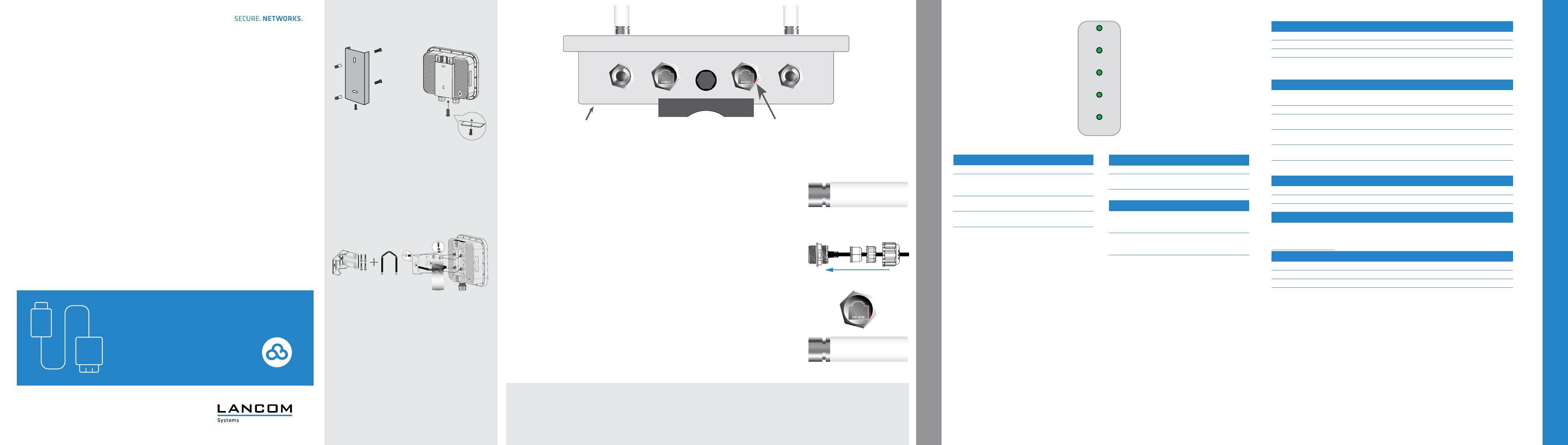
dGround connection (bottom of device)
Attach the enclosed grounding cable to the housing on one side with the enclosed M3 screw and to a suitable
grounding conductor on the other side.
eAntenna connectors 2.4 GHz
Screw the supplied 2.4 GHz antennas to the connectors labeled ‚2.4G‘ on the front and back of the device.
f
g
Ethernet interfaces LAN1 (PoE) / LAN2
The LAN1 (PoE) port supplies power to the device as well.
Prepare to mount the waterproof Ethernet cable by sliding the end cap A and then the clamp ring B over the
Ethernet connector D on the cable as shown in the adjacent figure.
Then place the two seal halves C between plug D and clamp ring B on the cable and join them together. Next,
insert plug D into LAN1 connector E on the device, carefully push all previously assembled parts towards plug D
and screw the end cap A to LAN1 connector E on the device.
Outdoor cable diameter: 6.5 mm to 8.5 mm
Connect the other end of the network cable to the ‚Power-Out‘ port of a suitable PoE injector. If required,
additionally connect the LAN2 interface to another network device via a waterproof Ethernet cable.
hReset button (accessible through the housing of the LAN2 socket)
To restore the default device configuration, use a suitable pointed object to carefully press the reset button in the
device through the recess in the housing of the LAN2 socket until the LEDs on the side of the device go out. During
the restart that now follows automatically, the device loads the default configuration.
iAntenna connectors 5 GHz
Screw the supplied 5 GHz antennas to the connectors labeled ‚5G‘ on the front and back of the device.
Power
LAN1
LAN2
2.4GHz
5GHz
Wall mounting
Use the mounting plate a as a drilling template to mark the drill
holes in a sufficiently load-bearing wall.
After setting the dowels, align the mounting plate and then fasten
it to the wall using the provided M6 screws.
Then position the access point in front of the mounting plate as
shown in graphic b and slide it down the guide. Then screw the
locking screw from below through the mounting plate into the
housing of the access point and tighten it.
Pole mounting
First screw the angle bracket c to the access point housing using
the provided screws. Note the positioning of the washers and lock
washers directly under the screw head. Then position the angle
bracket with the screwed-on access point on the mast, guide
the bracket d around the mast through the holes of the angle
bracket and fasten it with the enclosed nuts after aligning the
access point.
b
c
a
d
LAN1 (PoE)2.4G 5GLAN2
e f g h id
i e
D C B AE
