Page is loading ...

DWEHF1838K DWLHF2025K
If you have questions or comments, contact us.
Pour toute question ou tout commentaire, nous contacter.
Si tiene dudas o comentarios, contáctenos.
1-800-4-
DeWALT
Instruction Manual
Guide D’utilisation
Manual de instrucciones
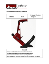
DWEHF1838K, DWLHF2025K
Hardwood Flooring Staplers
Engrapadoras Para Pisos De Madera
Agrafeuses Pour Bois Dur à Parquet

INTRODUCTION
The
DeWALT
DWEHF1838K and DWLHF2025K are precision-built tools, designed for high
speed, high volume fastening. These tools will deliver efficient, dependable service when
used correctly and with care. As with any fine power tool, for best performance the
manufacturer’s instructions must be followed. Please study this manual before operating
the tool and understand the safety warnings and cautions. The instructions on installation,
operation and maintenance should be read carefully, and the manuals kept for reference.
NOTE: Additional safety measures may be required because of your particular application of the tool.
Contact your
DeWALT
representative or distributor with any questions concerning the tool and its
use.
DeWALT
Industrial Tool Co., 701East Joppa Road, Towson, MD 21286, call 1-800-4-
DeWALT
(1-800-433-9258) or visit our website: www.dewalt.com.
INDEX
Safety Instructions ..............................................3
Tool Components ...............................................4
Tool/Fastener Specifications .......................................5
Air Supply and Connections .......................................6
Loading the Tool ................................................7
Adjustment Instructions ...........................................8
Tool Operation.................................................10
Tool Operation Check ........................................... 11
Maintaining the Pneumatic Tool ...................................11
Troubleshooting ..............................................12
Maintenance Checklist...........................................13
Other
DeWALT
Flooring Products ..................................14
NOTE:
DeWALT
tools have been engineered to provide excellent customer satisfaction and are designed
to achieve maximum performance when used with precision
DeWALT
fasteners engineered to the
same exacting standards.
DeWALT
cannot assume responsibility for product performance
if our tools are used with fasteners or accessories not meeting the specific requirements
established for genuine
DeWALT
nails, staples and accessories.
SEVEN YEAR LIMITED WARRANTY
D
e
WALT will repair, without charge, any defects due to faulty materials or workmanship for seven years from the
date of purchase. This warranty does not cover part failure due to normal wear or tool abuse. For further detail
of warranty coverage and warranty repair information, visit www.dewalt.com or call 1-800-4-D
e
WALT (1-800-
433-9258). This warranty does not apply to accessories or damage caused where repairs have been made or
attempted by others. This warranty gives you specific legal rights and you may have other rights which vary in
certain states or provinces.
In addition to the warranty, D
e
WALT tools are covered by our:
1 YEAR FREE SERVICE
D
e
WALT will maintain the tool and replace worn parts caused by normal use, for free, any time during the first year
after purchase. Nailer wear items, such as o-rings and driver blades, are not covered.
90 DAY MONEY BACK GUARANTEE
If you are not completely satisfied with the performance of your D
e
WALT Power Tool, Laser, or Nailer for any
reason, you can return it within 90 days from the date of purchase with a receipt for a full refund – no questions
asked.
LATIN AMERICA: This warranty does not apply to products sold in Latin America. For products sold in Latin
America, see country specific warranty information contained in the packaging, call the local company or see
website for warranty information.
FREE WARNING LABEL REPLACEMENT: If your warning labels become illegible or are missing, call
1-800-4-D
e
WALT (1-800-433-9258) for a free replacement.
-2-

SAFETY INSTRUCTIONS
EYE PROTECTION which conforms to ANSI specifications and provides protection against
flying particles both from the FRONT and SIDE should ALWAYS be worn by the operator
and others in the work area when connecting to air supply, loading, operating or servicing
this tool. Eye protection is required to guard against flying fasteners and debris, which
could cause severe eye injury.
The employer and/or user must ensure that proper eye protection is worn. Eye protection
equipment must conform to the requirements of the American National Standards
Institute, ANSI Z87.1 and provide both frontal and side protection. NOTE: Non-side shielded
spectacles and face shields alone do not provide adequate protection.
Additional Safety Protection will be required in some environments. For
example, the working area may include exposure to noise level which can
lead to hearing damage. The employer and user must ensure that any necessary hearing
protection is provided and used by the operator and others in the work area. Some
environments will require the use of head protection equipment. When required, the
employer and user must ensure that head protection conforming to ANSI Z89.1 is used.
AIR SUPPLY AND CONNECTIONS
Do not use oxygen, combustible gases, or bottled gases as a power source for this tool as
tool may explode, possibly causing injury.
Do not use supply sources which can potentially exceed 200 psig (14 kg/cm
2
) as tool may
burst, possibly causing injury.
The connector on the tool must not hold pressure when air supply is disconnected. If a
wrong fitting is used, the tool can remain charged with air after disconnecting and thus will
be able to drive a fastener even after the air line is disconnected possibly causing injury.
Do not pull trigger or depress contact arm while connected to the air supply as the tool may
cycle, possibly causing injury.
Always disconnect air supply: 1.) Before making adjustments; 2.) When servicing the tool;
3.) When clearing a jam; 4.) When tool is not in use; 5.) When moving to a different work
area, as accidental actuation may occur, possibly causing injury.
LOADING TOOL
When loading tool: 1.) Never place a hand or any part of body in fastener discharge area
of tool; 2.) Never point tool at anyone; 3.) Do not pull the trigger or depress the trip as
accidental actuation may occur, possibly causing injury.
OPERATION
Always handle the tool with care: 1.) Never engage in horseplay; 2.) Never pull the trigger
unless nose is directed toward the work; 3.) Keep others a safe distance from the tool while
tool is in operation as accidental actuation may occur, possibly causing injury.
The operator must not hold the trigger pulled on contact arm tools except during fastening
operation as serious injury could result if the trip accidentally contacted someone or
something, causing the tool to cycle.
Keep hands and body away from the discharge area of the tool. A contact arm tool may
bounce from the recoil of driving a fastener and an unwanted second fastener may be
driven possibly causing injury.
Check operation of the contact arm mechanism frequently. Do not use the tool if the arm is
not working correctly as accidental driving of a fastener may result. Do not interfere with
the proper operation of the contact arm mechanism.
Do not drive fasteners on top of other fasteners or with the tool at an overly steep angle as
this may cause deflection of fasteners which could cause injury.
Do not drive fasteners close to the edge of the work piece as the wood may split, allowing
the fastener to be deflected possibly causing injury.
This nailer produces SPARKS during operation. NEVER use the nailer near flammable
substances, gases or vapors including lacquer, paint, benzine, thinner, gasoline, adhesives,
mastics, glues or any other material that is -- or the vapors, fumes or by-products of which are
-- flammable, combustible or explosive. Using the nailer in any such environment could cause an
EXPLOSION resulting in personal injury or death to user and bystanders.
-3-

TOOL COMPONENTS
Frame
Protector
Trigger
Lockout
Air Fitting
Frame
Frame Cap
Over-Molded Comfort Grip
Adjustable Precision Knobs
Reload Indicator
Easy-Sight Tongue
Engagement
Magazine
Release Button
Rear Exhaust
Trigger
-4-
MAINTAINING THE TOOL
When working on air tools note the warnings in this manual and use extra care when
evaluating problem tools.
If the tool has been dropped or you suspect tool damage perform tool operation check
as defined in the tool operation check section.

TOOL SPECIFICATIONS
All dimensions in inches unless otherwise specified.
-5-
Operating Pressure
70 to 120 psig (4.9 - 8.4 kg/cm
2
). Select the operating pressure in this range for best fastener performance.
DO NOT EXCEED THIS RECOMMENDED OPERATING PRESSURE.
The DWEHF1838K requires 1.94 cubic feet per minute or cfm (55 liters per minute or L/min) of free air at
80 PSI (5.6 kg/cm
2
) to operate at a rate of 60 fasteners per minute. The DWLHF2025K requires 1.90 cubic
feet per minute or cfm (54 liters per minute or L/min) of free air at 80 PSI (5.6 kg/cm
2
) to operate at a rate
of 60 fasteners per minute. To determine the appropriately sized air compressor, take the actual rate
at which the tool will be run and compare the required cfm (L/min) to the compressor’s free air delivery
(cfm or L/min) at 80 PSI (5.6 kg/cm
2
).
For example, if your fastener usage averages 30 fasteners per minute, you need 50% of the required air volume
(cfm or L/min) that is required to operate the tool at the rate of 60 fasteners per minute. In this case, be sure
that your air compressor can deliver a minimum of 0.97 cfm (27.5 L/min) at 80 PSI (5.6 kg/cm
2
) for optimum
performance.
*Visit www.
DeWALT
.com for further details.
NOTE:
D
e
WALT tools have been engineered to provide superior customer satisfaction and are designed to achieve
maximum perfomance when used with precision D
e
WALT fasteners engineered to the same exacting standards.
D
e
WALT cannot assume responsibility for product performance if our tools are used with fasteners
or accessories not meeting the specific requirements established for genuine D
e
WALT fasteners
andaccessories.
DWEHF1838K DWLHF2025K
Description 18-ga Flooring Stapler 20-ga Flooring Stapler
Engine Type Oil-free Oil-free
Operation Pressure Range 70-120 psig (4.9 - 8.4 kg/cm
2
) 70-120 psig (4.9 - 8.4 kg/cm
2
)
Maximum Operation Pressure 120 psig (8.4 kg/cm
2
) 120 psig (8.4 kg/cm
2
)
Fastener Type DNS181XX-2 Series DWCS20100
Fastener Gauge 18 Gauge 20 Gauge
Fastener Range 1” - 1-1/2” (25 mm - 38 mm) 1” (25 mm)
Magazine Capacity 100 125
Length 9-1/4” (235 mm) 9-1/4” (235 mm)
Width 2-3/4” (70 mm) 2-3/4” (70 mm)
Height 9-7/8” (251 mm) 8.5” (216 mm)
Weight 3.5 lb (1.57 kg) 2.9 lb (1.32 kg)
Tool Model
Fastener
Type
Fastener SKU
Crown
Width
Gauge Length
DWEHF1838K Staples
DNS18100-2 1/4” (6.3 mm) 18
1”
(25 mm)
DNS18125-2 1/4” (6.3 mm) 18
1-1/4”
(31.75 mm))
DNS18150-2 1/4” (6.3 mm) 18
1-1/2”
(38 mm)
DWLHF2025K Staples
DWCS20100
3/16”
(4.7 mm)
20
1”
(25 mm)
FASTENER SPECIFICATIONS

-6-
AIR SUPPLY AND CONNECTIONS
Do not use oxygen, combustible gases, or bottled gases as a power source for this tool as
tool may explode, possibly causing injury.
FITTINGS
Install a male plug on the tool which is free flowing and which will release air pressure from the tool when
disconnected from the supply source.
HOSES
Air hoses should have a minimum of 150 psig (10.6 kg/cm
2
) working pressure rating or 150 percent of the
maximum pressure that could be produced in the air system. The supply hose should contain a fitting that will
provide “quick disconnecting” from the male plug on the tool.
SUPPLY SOURCE
Use only clean regulated compressed air as a power source for this tool. NEVER USE OXYGEN, COMBUSTIBLE
GASES, OR BOTTLED GASES, AS A POWER SOURCE FOR THIS TOOL AS TOOL MAY EXPLODE.
REGULATOR
A pressure regulator with an operating pressure of 0 - 125 psig (0 - 8.8 kg/cm
2
) is required to control the operating
pressure for safe operation of this tool. Do not connect this tool to air pressure which can potentially exceed 200
psig (14 kg/cm
2
) as tool may fracture or burst, possibly causing injury.
OPERATING PRESSURE
Do not exceed recommended maximum operating pressure as tool wear will be greatly increased. The air supply
must be capable of maintaining the operating pressure at the tool. Pressure drops in the air supply can reduce
the tool’s driving power. Refer to “TOOL SPECIFICATIONS” for setting the correct operating pressure for the tool.
Quick Connect Plug
Quick Disconnect Plug

-7-
LOADING THE DWEHF1838K & DWLHF2025K
EYE PROTECTION which conforms to ANSI specifications and provides protection against
flying particles both from the FRONT and SIDE should ALWAYS be worn by the operator
and others in the work area when connecting to air supply, loading, operating or servicing
this tool. Eye protection is required to guard against flying fasteners and debris, which
could cause severe eye injury.
The employer and/or user must ensure that proper eye protection is worn. Eye protection
equipment must conform to the requirements of the American National Standards
Institute, ANSI Z87.1 and provide both frontal and side protection. NOTE: Non-side
shielded spectacles and face shields alone do not provide adequate protection.
TO PREVENT ACCIDENTAL INJURIES:
• Never place a hand or any other part of the body in nail discharge area of tool while
the air supply is connected.
• Never point the tool at anyone else.
• Never engage in horseplay.
• Never pull the trigger unless nose is directed at the work.
• Always handle the tool with care.
• Do not pull the trigger or depress the trip mechanism while loading the tool.
LOADING THE DWEHF1838K & DWLHF2025K
1. Depress magazine release button and pull
back magazine.
2. Open magazine fully and turn tool sideways
with discharge area pointed away from
yourself and others. Load staples in
channel.
3. Push magazine forward until latch is
engaged.

-8-
ADJUSTMENT INSTRUCTIONS
FLOOR
VAPOR BARRIER
SUBFLOOR
NOSE
KNOB
FRONT GUIDE
TONGUE OF FLOORING
FOOT
TO ADJUST THE TOOL TO THE FLOORING
1. Loosen both Knobs until the Foot and Front Guide move freely.
2. Engage the Nose with the Tongue of Flooring.
3. Push the Front Guide to the subfloor and the Foot to the flooring.
4. Tighten both Knobs.
Refer to the flooring manufactures installation instructions for proper fastener and
fastening technique.
IMPORTANT: Test the tool on a scrap piece of flooring to ensure proper staple placement and
compatibility.
DeWALT
cannot assume responsibility for product performance if the tool is used
improperly or not in accordance with the flooring manufacturer’s installation instructions.
With tool properly located on tongue of flooring,
slide the tool along the tongue without lifting the
tool off the floor while fastening as shown above
and to the left.
AIR PRESSURE:
Air pressure must be adjusted to properly
countersink the staples. Air pressure should be
set using a scrap piece of flooring to adjust the air
pressure for correct countersinking.
(See following page)

-9-
FLOOR
BEFORE OPERATING THIS TOOL, STUDY THESE INSTRUCTIONS AND OPERATION
AND MAINTENANCE MANUAL FOR YOUR TOOL TO UNDERSTAND THE SAFETY
WARNINGS AND INSTRUCTIONS. IF YOU HAVE ANY QUESTIONS, CONTACT YOUR
DeWALT
REPRESENTATIVE OR DISTRIBUTOR. SAVE THESE INSTRUCTIONS FOR FUTURE
REFERENCE.
• Air pressure too low.
• Staple crown above tongue.
• Increase air pressure.
• Air pressure too high.
• Staple buried.
• Lower air pressure.
• Correct air pressure.
• Staple just below surface.
STAPLE

TOOL OPERATION
EYE PROTECTION which conforms to ANSI specifications and provides protection against
flying particles both from the FRONT and SIDE should ALWAYS be worn by the operator
and others in the work area when connecting to air supply, loading, operating or servicing
this tool. Eye protection is required to guard against flying fasteners and debris, which
could cause severe eye injury.
The employer and/or user must ensure that proper eye protection is worn. Eye protection
equipment must conform to the requirements of the American National Standards
Institute, ANSI Z87.1 and provide both frontal and side protection. NOTE: Non-side shielded
spectacles and face shields alone do not provide adequate protection.
BEFORE HANDLING OR OPERATING THIS TOOL:
I. READ AND UNDERSTAND THE WARNINGS CONTAINED IN THIS MANUAL.
II. REFER TO “TOOL SPECIFICATIONS” IN THIS MANUAL TO IDENTIFY THE OPERATING SYSTEM
ON YOUR TOOL.
OPERATION
The operator must not hold the trigger pulled on contact trip tools except during fastening
operation, as serious injury could result if the trip accidentally contacted someone or
something, causing the tool to cycle.
Keep hands and body away from the discharge area of the tool. A contact trip tool may
bounce from the recoil of driving a fastener and an unwanted second fastener may be
driven, possibly causing injury.
SEQUENTIAL TRIP OPERATION:
In SEQUENTIAL TRIP MODE the contact trip operates in conjunction with the trigger to drive a fastener.
To operate a sequential trip tool, first position the contact trip on the work surface WITHOUT PULLING
THE TRIGGER. Depress the contact trip and then pull the trigger to drive a fastener. As long as the contact
trip is contacting the work and is held depressed, the tool will drive a fastener each time the trigger is
depressed. If the contact trip is allowed to leave the work surface, the sequence described above must be
repeated to drive another fastener.
If the tool has been dropped or you suspect tool damage perform tool operation check as
defined in the tool operation check section.
IN ADDITION TO THE OTHER WARNINGS CONTAINED
IN THIS MANUAL OBSERVE THE FOLLOWING FOR
SAFEOPERATION
• Use the
DeWALT
pneumatic tool only for the purpose for which it was designed.
• Never use this tool in a manner that could cause a fastener to be directed toward the user
or others in the work area.
• Do not use the tool as a hammer.
• Always carry the tool by the handle. Never carry the tool by the air hose.
• Do not alter or modify this tool from the original design or function without approval from
DeWALT
.
• Always be aware that misuse and improper handling of this tool can cause injury to
yourself and others.
• Never clamp or tape the trigger or contact trip in an actuated position.
• Never leave a tool unattended with the air hose attached.
• Do not operate this tool if it does not contain a legible WARNING LABEL.
• Do not continue to use a tool that leaks air or does not function properly. Notify your nearest
DeWALT
representative if your tool continues to experience functional problems.
-10-

-11-
TOOL OPERATION CHECK
Remove all fasteners from tool before performing tool operation check.
If the tool is dropped or you suspect tool damage perform tool operation check.
SEQUENTIAL TRIP OPERATION:
A. Press the contact trip against the work surface, without touching the trigger.
THE TOOL MUST NOT CYCLE.
B. Hold the tool off the work surface and pull the trigger.
THE TOOL MUST NOT CYCLE.
Release the trigger. The trigger must return to the trigger stop on the frame.
C. Pull the trigger and press the contact trip against the work surface.
THE TOOL MUST NOT CYCLE.
D. With finger off the trigger, press the contact trip against the work surface. Pull the trigger.
THE TOOL MUST CYCLE.
MAINTAINING THE PNEUMATIC TOOL
When working on air tools, note the warnings in this manual and use extra care evaluating
problem tools.
If the tool has been dropped or you suspect tool damage perform tool operation check as
defined in the tool operation check section.
Pusher spring (constant force spring). Caution must be used when working with the
spring assembly. The spring is wrapped around, but not attached to, a roller. If the
spring is extended beyond its length, the end will come off the roller and the spring will
roll up with a snap, with a chance of pinching your hand. Also the edges of the spring
are very thin and could cut. Care must also be taken to insure no permanent kinks are
put in the spring as this will reduce the springs force.
REPLACEMENT PARTS
Use only genuine
DeWALT
replacement parts. Do not use modified parts.
ASSEMBLY PROCEDURE FOR SEALS
When repairing a tool, make sure the internal parts are clean and lubricated. Use Parker “O”-LUBE, Magnalube,
or equivalent on all “O”-rings. Coat each “O”-ring with lubricant before assembling.
AIR SUPPLY-PRESSURE AND VOLUME
Air volume is as important as air pressure. The air volume supplied to the tool may be inadequate because of
undersize fittings and hoses, or from the effects of dirt and water in the system. Restricted air flow will prevent the
tool from receiving an adequate volume of air, even though the pressure reading is high. The results will be slow
operation, misfeeds or reduced driving power. Before evaluating tool problems for these symptoms, trace the air
supply from the tool to the supply source for restrictive connectors, low points containing water and anything else
that would prevent full volume flow of air to the tool.

-12-
TROUBLESHOOTING
PROBLEM CAUSE CORRECTION
Trigger valve housing leaks air O-ring cut or cracked ....................Replace O-ring
Trigger valve stem leaks air O-ring/seals cut or cracked ..............Replace trigger valve assembly
Frame/nose leaks air O-ring or gasket is cut or cracked. . . . . . . . . Replace O-ring or gasket
Bumper cracked/worn ................... Replace bumper
Frame/cap leaks air Damaged gasket or seal .................Replace gasket or seal
Cracked/worn head valve ...............Replace head valve
Loose cap screws ......................Tighten and recheck
Failure to cycle Air supply restriction ....................Check air supply equipment
Worn head valve .......................Replace head valve
Broken cylinder cap spring ...............Replace cylinder cap spring
Head valve stuck in cap .................Disassemble / Check / Lubricate
Lack of power; slow to cycle Broken cylinder cap spring ...............Replace cap spring
Rings/seals cut or cracked ............... Replace rings/seals
Exhaust blocked ........................Check bumper, head valve spring
Trigger assembly worn/leaks .............Replace trigger assembly
Dirt/tar build up on driver ................Disassemble nose/driver to clean
Cylinder sleeve not seated correctly
on bottom bumper ......................Disassemble to correct
Air pressure too low .....................Check air supply equipment
Skipping fasteners;
intermittent feed Worn bumper ...........................Replace bumper
Tar/dirt in driver channel .................Disassemble and clean nose and driver
Air restriction/inadequate air flow through
quick disconnect socket and plug ......... Replace quick disconnect fittings
Worn piston ring ........................Replace ring, check driver
Damaged pusher spring .................Replace spring
Low air pressure ........................ Check air supply system to tool
Loose magazine nose screws ............Tighten all screws
Fasteners too short for tool. . . . . . . . . . . . . . . Use only recommended fasteners
Bent fasteners .......................... Discontinue using these fasteners
Wrong size fasteners .................... Use only recommended fasteners
Leaking head cap gasket ................Tighten screws/replace gasket
Trigger valve O-ring cut/worn ............Replace O-ring
Broken/chipped driver ................... Replace driver (check piston ring)
Dry/dirty magazine ......................Clean/lubricate use
DeWALT
Air Tool Lubricant
Worn magazine ......................... Replace magazine
Fasteners jam in tool Driver channel worn ....................Replace nose/check door
Wrong size fasteners .................... Use only recommended fasteners
Bent fasteners .......................... Discontinue using these fasteners
Loose magazine/nose screws ............Tighten all screws
Broken/chipped driver ................... Replace driver

-13-
MAINTENANCE CHECKLIST
Maintenance Benefit Procedure Service Interval
Inspect trigger performance Ensure trigger system is in
proper working order
Refer to Tool Operation Check
section in this manual
Daily
Drain condensation from air
compressor tanks and air filters
(if present)
Prevents accumlation of
moisture that can impede tool
performace
Open drain cock on tanks and air
filters and drain all condensate
Daily
Clean magazine assembly Prevents accumlation of debris
that could cause a jam
Blow clean with compressed air Daily
Clean nose assembly Prevents accumlation of debris
that could cause a jam
Blow clean with compressed air Daily
Ensure all fasteners remain tight Prevent loose parts Tighten all fasteners with
appropriately sized hex wrench
Weekly
Replace air fitting Maintains proper air flow to
engine for peak performance
Remove worn air fitting and
replace with new fitting
50,000 Fasteners
Replace piston/driver assembly Maintains consistent drive
quality
Refer to replacement part kit
instructions
150,000 Fasteners
Replace O-rings Maintains engine for peak
performance
Refer to replacement part kit
instructions
250,000 Fasteners
Replace bumper Maintains engine for peak
performance
Refer to replacement part kit
instructions
250,000 Fasteners
Replace headvalve Maintains engine for peak
performance
Refer to replacement part kit
instructions
250,000 Fasteners
Replace engine cylinder Maintains engine for peak
performance
Refer to replacement part kit
instructions
500,000 Fasteners

-14-
OTHER
DeWALT
FLOORING PRODUCTS
DWMIIIFS
15.5 GAUGE
FLOORING STAPLER
DWMIIIFN
16 GAUGE FLOORING NAILER
DWMFN-201
16 GAUGE MANUAL
FLOORING NAILER
DWFP12569
2-IN-1 15.5 GAUGE FLOORING
STAPLER AND 16 GAUGE
CLEAT NAILER
For more information log on to:
www.
DeWALT
.com

-15-
INTRODUCCIÓN
Los modelos D
e
WALT DWEHF1838K y DWLHF2025K son herramientas construidas a precisión, diseñadas
para funcionar a alta velocidad y con alto volumen. Estas herramientas entregan un servicio eficiente y fiable
cuando se usan correctamente y con cuidado. Al igual que con toda herramienta automática de calidad, deben
seguirse las instrucciones del fabricante para obtener el óptimo rendimiento. Estudie este manual antes de
operar la herramienta y tome nota de las advertencias y precauciones de seguridad. Deben leerse en detalle
las instrucciones sobre la instalación, operación y mantenimiento, y deben conservarse los manuales para
referencia. NOTA: Pueden necesitarse medidas adicionales de seguridad según la aplicación particular de
la herramienta. Comuníquese con su representante o distribuidor de DeWALT por cualquier pregunta sobre
la herramienta y su uso. DEWALT Industrial Tool Co., 701 East Joppa Road, Towson, MD 21286, llamada
1-800-4-D
e
WALT (1-800-433-9258) o visite nuestro sitio web www.dewalt.com.
ÍNDICE
Instrucciones de seguridad .......................................16
Componentes de las herramientas .................................17
Especificaciones de la herramienta/Sujetador .........................18
Suministro de aire y conexiones ...................................19
Cargar la herramienta ...........................................20
Instrucciones de ajuste ..........................................21
Operación de la herramienta . . . . . . . . . . . . . . . . . . . . . . . . . . . . . . . . . . . . . . 23
Revisión funcional de la herramienta ................................24
Mantenimiento de la herramienta neumática .........................24
Solución de problemas ..........................................25
Lista de verificación de mantenimiento ..............................26
Otros productos
DeWALT
para pisos ...............................27
NOTA:
Las herramientas
DeWALT
se han diseñado para brindar una satisfacción excelente al cliente y lograr máximo
rendimiento al utilizarse con fijaciones de precisión
DeWALT
diseñadas con las mismas normas estrictas.
DeWALT
no puede asumir responsabilidad alguna por el rendimiento del producto si se utilizan
nuestras herramientas con fijaciones o accesorios que no reúnen los requisitos específicos establecidos
para los clavos, grapas y accesorios genuinos de
DeWALT
.
GARANTÍA LIMITADA POR SIETE AÑOS
DeWALT
reparará, sin cargo alguno, los defectos en materiales o por mano de obra defectuosa por siete años
a partir de la fecha de compra. Esta garantía no cubre la falla de piezas debido al desgaste normal o abuso de
la herramienta. Para obtener más información sobre la cobertura de la garantía y la información de reparación
de la garantía, visite www.dewalt.com o llame al 1 800 433-9258 (1 800 4-
DeWALT
). Esta garantía no se aplica
a accesorios o daños causados en caso de que terceros realicen o intenten realizar reparaciones. Esta garantía
le proporciona derechos legales específicos y usted puede tener otros derechos que varían en ciertos estados
o provincias.
Además de esta garantía, las herramientas
DeWALT
están cubiertas por nuestro:
SERVICIO GRATUITO DE 1 AÑO
DeWALT
mantendrá la herramienta y reemplazará las piezas desgastadas por el uso normal sin costo y en
cualquier momento durante el primer año después de la compra. Los elementos que sufren desgaste de la
clavadora, como juntas tóricas y hojas de transmisión, no están cubiertos.
GARANTÍA DE REEMBOLSO DE 90 DÍAS
Si usted no está completamente satisfecho con el rendimiento de su herramienta eléctrica, láser o clavadora
DeWALT
por algún motivo, puede devolverlos dentro de los 90 días posteriores a la fecha de compra con un
recibo para obtener un reembolso completo, sin ninguna pregunta.
AMÉRICA LATINA: Esta garantía no es de aplicación a productos vendidos en América Latina. Para productos
vendidos en América Latina, consulte la información de la garantía específica del país incluida en el embalaje,
contacte a la compañía local o consulte el sitio web para obtener información acerca de la garantía.
REEMPLAZO GRATUITO DE LA ETIQUETA DE ADVERTENCIA: Si sus etiquetas de advertencia son ilegibles
o se extravían, llame al 1 800 433-9258 (1 800 4-
DeWALT
) para obtener un reemplazo gratuito.

-16-
INSTRUCCIONES DE SEGURIDAD
El operador y otros en el área SIEMPRE deben llevar PROTECCIÓN OCULAR en conformidad con las
especificaciones ANSI y que proteja contra partículas que vuelen por DELANTE y por el LADO, cuando
se haga la conexión al suministro de aire, así como al cargar, operar o dar servicio a esta herramienta.
Se exige protegerse la vista para resguardarse contra fijaciones o residuos que vuelen, lo cual puede
causar lesiones graves a los ojos.
El empleador y/o el usuario deben asegurar que se protejan debidamente los ojos. El equipo de
protección ocular debe estar en conformidad con los requisitos del Instituto Nacional Americano de
Normas (American National Standards Institute), ANSI Z87.1 y proteger por delante y por el costado.
NOTA: Los anteojos o caretas sin protección lateral por sí solos no dan una protección adecuada.
ATENCIÓN:
En algunos ambientes se necesitará protección adicional de seguridad. Por ejemplo, el
área de trabajo puede exponer a un nivel de ruido que lesione el oído. El empleador y
el usuario deben comprobar que se cuente con la protección necesaria del oído y que el operador y los
demás presentes en el área la usen. Algunos ambientes exigirán el uso de casco protector. Cuando sea
necesario, el empleador y el usuario deben verificar que se proteja la cabeza en conformidad con la
norma ANSI Z89.1.
SUMINISTRO DE AIRE Y CONEXIONES
No use oxígeno, gases combustibles ni gases envasados en cilindros para operar esta herramienta
porque puede explotar, causando posibles lesiones.
No use fuentes de suministro que tengan el potencial de superar 14 kg/cm
2
(200 psig) dado que la
herramienta puede explotar, causando posibles lesiones.
El conector de la herramienta no debe contener presión cuando se desconecte el suministro de
aire. Si se usa el conector indebido, la herramienta puede mantenerse cargada con aire después de
desconectarla y podría impulsar una fijación incluso después de desconectar la línea de aire, causando
posibles lesiones.
No accione el gatillo ni oprima el brazo de contacto mientras esté conectado al suministro de aire
porque la herramienta puede hacer un ciclo, causando posibles lesiones.
Siempre desconecte el suministro de aire: 1.) Antes de hacer ajustes; 2.) Al dar servicio a la
herramienta; 3.) Al despejar un atasco; 4.) Cuando no está en uso la herramienta; 5.) Al avanzar a
otra área de trabajo, porque puede activarse accidentalmente, causando posibles lesiones.
CARGA DE LA HERRAMIENTA
Al cargar la herramienta: 1.) Nunca ponga la mano ni ninguna otra parte del cuerpo en el área aplicadora
de descarga de la herramienta; 2.) Nunca apunte la herramienta a ninguna persona; 3.) No accione el
gatillo ni pulse el disparador porque puede activarse accidentalmente, causando posibles lesiones.
FUNCIONAMIENTO
Siempre maneje la herramienta con cuidado: 1.) Nunca participe en juegos rudos; 2.) Nunca accione
el gatillo a menos que la punta esté dirigida hacia el trabajo; 3.) Mantenga a los demás a una distancia
segura de la herramienta mientras esté en funcionamiento porque puede activarse accidentalmente,
causando posibles lesiones.
El operador no debe sostener el gatillo accionado en las herramientas con brazos de contacto salvo
durante la aplicación de fijaciones ya que pueden ocurrir lesiones graves si el disparo tomara contacto
accidentalmente con algo o alguien, ocasionando que la herramienta haga un ciclo.
Mantenga las manos y el cuerpo alejados del área de descarga de la herramienta. Una herramienta con
brazo de contacto puede rebotar al aplicar una fijación haciendo salir otra, causando posibles lesiones.
Revise frecuentemente el funcionamiento del mecanismo del brazo de contacto. No use la
herramienta si el brazo no funciona correctamente ya que puede impulsarse accidentalmente una
fijación. No interfiera con el funcionamiento adecuado del mecanismo del brazo de contacto.
No aplique clavos o grapas encima de otras ni con la herramienta en un ángulo demasiado agudo pues
esto puede ocasionar su deflexión, pudiendo causar lesiones.
No aplique grapas cerca del borde de la pieza con la cual esté trabajando pues la madera puede
dividirse, permitiendo la deflexión del clavo o grapa, causando posibles lesiones.
Esta clavadora produce CHISPAS durante la operación. NUNCA use la clavadora cerca de sustancias,
gases ni vapores inflamables, incluidos lacas, pintura, bencina, gasolina, adhesivos, mástique,
pegamentos ni ningún otro material que sea inflamable, combustible o explosivo -- o vapores,
emanaciones o subproductos que puedan serlo. Si se usa la clavadora en cualquier ambiente de
este tipo podría causar una EXPLOSIÓN produciendo lesiones físicas o fatales para el usuario y las
personas en la cercanía.

-17-
MANTENIMIENTO DE LA HERRAMIENTA
Al trabajar con herramientas neumáticas, observe las advertencias de este manual y tenga sumo
cuidado al evaluar herramientas con problemas.
Si la herramienta se ha caído o si sospecha daño a la herramienta, realice una comprobación
de funcionamiento de la herramienta tal como se define en la sección de comprobación de
funcionamiento de la herramienta.
COMPONENTES DE LA HERRAMIENTA
Gatillo
Bloqueo
del gatillo
Tapa del armazón
Perillas de precisión ajustables
Indicador de recarga
Enganche de le
lengüeta Easy-Sight
Depósito Botón
de liberación
Protector del
armazón
Armazón
Escape posterior
Conector de
aire
Agarre cómodo sobremoldeado

ESPECIFICACIONES DE LA HERRAMIENTA
Todas las dimensiones están en pulgadas a menos que se especifique lo contrario.
Presión operativa
4 ,9 a 8,4 kg/cm
2
(70 a 120 psig). Seleccione la presión de operación dentro de este rango para el mejor
desempeño del sujetador.
Consumo de aire
La DWEHF1838K requiere 55 litros por minuto o L/min (1.94 pies cúbicos por minuto o cfm) de aire libre a
5.6kg/cm
2
(80 PSI) para operar a una velocidad de 60 sujetadores por minuto. La DWLHF2025K requiere 54
litros por minuto o L/min (1.90 pies cúbicos por minuto o cfm) de aire libre a 5.6 kg/cm
2
(80 PSI) para operar a
una velocidad de 60 sujetadores por minuto. Para determinar el tamaño adecuado del compresor de aire, tome
la velocidad real en la cual se utilizará la herramienta y compare los L/min (cfm) requeridos con la entrega de
aire libre (FAD) del compresor (L/min o cfm) a 5.6 kg/cm
2
(80 PSI).
Por ejemplo, si usted usa en promedio 30 sujetadores por minuto, necesita el 50 % del volumen de aire (L/min
o cfm) que se requiere para operar la herramienta a una velocidad de 60 sujetadores por minuto. En este caso,
para un rendimiento óptimo, asegúrese de que su compresor de aire pueda entregar un mínimo de 27.5 L/min
(0.97 cfm) a 5.6 kg/cm
2
(80 PSI).
* Si desea obtener más detalles, visite www.
DeWALT
.com.
NOTA:
Las herramientas
DeWALT
se han diseñado para brindar una satisfacción excelente al cliente y lograr máximo rendimiento
al utilizarse con fijaciones de precisión
DeWALT
diseñadas con las mismas normas estrictas.
DeWALT
no puede asumir
responsabilidad alguna por el rendimiento del producto si se utilizan nuestras herramientas con fijaciones
o accesorios que no reúnen los requisitos específicos establecidos para fijaciones y accesorios genuinos
de
DeWALT
.
-18-
NO SUPERE ESTA PRESIÓN OPERATIVA RECOMENDADA.
ESPECIFICACIONES DE FIJACIONES
DWEHF1838K DWLHF2025K
Descripción Engrapadora para duela calibre18 Engrapadora para duela calibre 20
Tipo de motor Sin aceite Sin aceite
Rango de presión operativa 4,9 - 8,4 kg/cm
2
(70 a 120 psig) 4,9 - 8,4 kg/cm
2
(70 a 120 psig)
Máxima presión operativa 8,4 kg/cm
2
(120 psig) 8,4 kg/cm
2
(120 psig)
Tipo de fijación Serie DNS181XX-2 DWCS20100
Calibre de la fijación Calibre 18 Calibre 20
Gama de la fijación 25 mm - 38 mm (1" a 1-1/2") 25 mm (1")
Capacidad del depósito 100 125
Largo 235 mm (9-1/4") 235 mm (9-1/4")
Ancho 70 mm (2-3/4") 70 mm (2-3/4")
Altura 251 mm (9-7/8") 216 mm (8,5")
Peso
1,57 kg (3,5 lb) 1,32 kg (2,9 lb)
Modelo de
herramienta
Tipo de
fijación
SKU de
la fijación
Ancho
de corona
Calibre Largo
DWEHF1838K
Grapas
DNS18100-2 (6,3 mm) 1/4" 18 25 mm (1")
DNS18125-2 (6,3 mm) 1/4" 18 31,75 mm (1-1/4")
DNS18150-2 (6,3 mm) 1/4" 18 38 mm (1-1/2")
DWLHF2025K
Grapas DWCS20100 4,7 mm (3/16") 20 25 mm (1")

-19-
SUMINISTRO DE AIRE Y CONEXIONES
No use oxígeno, gases combustibles ni gases envasados en cilindros para operar esta herramienta
porque puede explotar, causando posibles lesiones.
CONECTORES
Instale un enchufe macho en la herramienta que está fluyendo libremente y que liberará presión de aire de la herramienta
al desconectarse de la fuente de alimentación.
MANGUERAS
Las mangueras de aire deben tener una presión nominal de trabajo mínima de 10.6 kg/cm
2
(150 psig) de capacidad nominal
de presión de trabajo o un 150 por ciento de la presión máxima que podría producirse en el sistema de aire. La manguera
de suministro debe contar con un conector de “desconexión rápida” del enchufe macho en la herramienta.
FUENTE DE SUMINISTRO
Use solamente aire comprimido regulado limpio como fuente de energía para esta herramienta. NUNCA USE OXÍGENO,
GASES COMBUSTIBLES O GASES ENVASADOS EN CILINDROS COMO FUENTE DE ENERGÍA PARA ESTA
HERRAMIENTA, PUES LA HERRAMIENTA PUEDE EXPLOTAR.
REGULADOR
Se necesita un regulador de presión con una presión operativa de 0 - 8.8 kg/cm
2
(0 a 125 psig) para controlar la presión
operativa con el fin de que la herramienta funcione en forma segura. No conecte esta herramienta a la presión de aire
que potencialmente pueda superar 14 kg/cm
2
(200 psig) porque la herramienta puede fracturarse o explotar, causando
posibles lesiones.
PRESIÓN OPERATIVA
No supere la presión operativa máxima recomendada porque aumentará considerablemente el desgaste de la
herramienta. El suministro de aire debe ser capaz de mantener la presión operativa de la herramienta. Las caídas de
presión en el suministro de aire pueden reducir la energía impulsora de la herramienta. Consulte las “OPERACIÓN DE LA
HERRAMIENTA” para establecer la presión operativa correcta de la herramienta.
Enchufe de conexión
rápida
Enchufe de
desconexión rápida

-20-
CARGA DE LA DWEHF1838K & DWLHF2025K
1. Oprima el botón de liberación del depósito y
mueva hacia atrás el depósito.
2. Abra el depósito totalmente y gire la herramienta de
lado con el área de descarga apuntando lejos de
usted y de otras personas. Cargue las grapas en el
canal.
3. Empuje el depósito hacia delante hasta que se
enganche el pestillo.
CARGA DE LA DWEHF1838K Y LA DWLHF2025K
El operador y otros en el área SIEMPRE deben llevar PROTECCIÓN OCULAR en conformidad
con las especificaciones ANSI y que proteja contra partículas que vuelen por DELANTE y
por el LADO, cuando se haga la conexión al suministro de aire, así como al cargar, operar
o dar servicio a esta herramienta. Se exige protegerse la vista para resguardarse contra
fijaciones o residuos que vuelen, lo cual puede causar lesiones graves a los ojos.
El empleador o el usuario deben asegurar que se protejan debidamente los ojos. El equipo
de protección ocular debe estar en conformidad con los requisitos del Instituto Nacional
Americano de Normas (American National Standards Institute), ANSI Z87.1 y proteger por
delante y por el costado. NOTA: Los anteojos o caretas sin protección lateral por sí solos
no dan una protección adecuada.
PARA PREVENIR LESIONES ACCIDENTALES:
• Nunca coloque la mano ni ninguna parte del cuerpo en el área de descarga de clavos de
la herramienta mientras esté conectado el suministro de aire.
• Nunca apunte la herramienta hacia una persona.
• Nunca participe en juegos rudos.
• Nunca accione el gatillo a menos que la punta esté dirigida hacia el trabajo.
• Siempre maneje la herramienta con cuidado.
• No accione el gatillo ni oprima el mecanismo de disparo mientras carga la herramienta.
/