
OPERATOR’S MANUAL
Generating set and industrial engines
16 liter (EMS 2)

CALIFORNIA PROPOSITION 65 WARNING
Engine exhaust, some of its constituents, and a broad range of engine parts are known to the State of California to cause cancer, birth
defects, and other reproductive harm. Additionally, lubricants, fuels, and other uids used in engines–including any waste created through
the wearing of engine parts–contain or produce chemicals known to the State of California to cause cancer and birth defects or other
reproductive harm.
Battery posts, terminals, and related accessories contain lead and lead compounds. Wash your hands after handling. Used engine oil
contains chemicals that have caused cancer in laboratory animals. Always protect your skin by washing thoroughly with soap and water.
This Operator’s Manual may be ordered in a diffe-
rent language free of charge up to 12 months after delivery,
via internet.
http://vppneuapps.volvo.com/manual/coupon/
If internet access isn‘t possible, please contact your
Volvo Penta dealer.
Diese Betriebsanleitung kann bis zu 12 Monate
nachder Lieferung über Internet kostenlos in einer anderen
Sprache bestellt werden.
http://vppneuapps.volvo.com/manual/coupon/
Wenn Sie keinen Internet-Zugriff haben, kontaktieren
Sie bitte Ihren Volvo Penta-Händler.
Ce manuel d‘utilisation peut être commandé gratu-
itement sur Internet en différentes langues, jusqu‘à 12 mois
après la date de livraison.
http://vppneuapps.volvo.com/manual/coupon/
Veuillez contacter votre Distributeur Volvo Penta si vous
avez un problème d‘accès à l‘Internet.
El presente libro de instrucciones puede solicitarse
en otro idioma diferente, libre de cargo, hasta 12 meses
después de la entrega, mediante internet.
http://vppneuapps.volvo.com/manual/coupon/
Si no se tiene acceso a internet, contacten al su concesio-
nario Volvo Penta.
Denna instruktionsbok kan beställas via internet på
ett annat språk gratis i upp till 12 månader efter leverans.
http://vppneuapps.volvo.com/manual/coupon/
Kontakta din Volvo Penta-återförsäljare om du inte har till-
gång till internet.
Dit instructieboek kan gratis via internet in een a
dere taal worden besteld tot 12 maanden na aevering.
http://vppneuapps.volvo.com/manual/coupon/
Als toegang tot het internet niet mogelijk is, neem dan
contact op met uw Volvo Penta dealer.
Denne instruktionsbog kan bestilles gratis på et an-
det sprog via Internettet i op til 12 måneder efter leveringen.
http://vppneuapps.volvo.com/manual/coupon/
Hvis det ikke er muligt at bestille via Internettet, bedes du
kontakte din Volvo Penta forhandler.
Tämä käyttöohjekirja on tilattavissa Internetin kau-
tta veloituksetta eri kielillä 12 kuukauden ajan toimituksen
jälkeen.
http://vppneuapps.volvo.com/manual/coupon/a
Jos sinulla ei ole Internet-yhteyttä, ota yhteys lähimpään
Volvo Penta jälleenmyyjään.
Este Manual do Operador pode ser encomendad
em idiomas diferentes isento de custos até 12 meses após
entrega, via internet.
http://vppneuapps.volvo.com/manual/coupon/
Se não for possível aceder à internet, contacte o seu con-
cessionário Volvo Penta.
To παρόν Βιβλίο Χρήσης μπορεί να παραγγελθεί
δωρεάν σε άλλη γλώσσα μέχρι 12 μήνες μετά την
παράδοση,μέσω διαδικτύου.
http://vppneuapps.volvo.com/manual/coupon/
Εάν δεν είναι δυνατή η πρόσβαση στο
διαδίκτυο,παρακαλούμε επικοινωνήστε με το δικό σας
Данное руководство по эксплуатации можно
бес-платно заказать на другом языке по Интернету в
течение 12 месяцев после доставки.
http://vppneuapps.volvo.com/manual/coupon/
Если доступ к Интернету отсутствует, обратитесь к
своему дилеру компании Volvo Penta.
Bu Kullanım Kılavuzu, teslimden 12 ay sonrasına
kadar İnternet yoluyla ücretsiz olarak farklı bir dilde sipariş
edilebilir.
http://vppneuapps.volvo.com/manual/coupon/
İnternet mümkün değilse, lütfen Volvo Penta yetkili
satıcınızla tmasa geçin.
Il manuale per l‘operatore può essere ordinato tra-
miteInternet, in varie lingue e per consegna gratuita, entro
12 mesi dalla consegna del prodotto
http://vppneuapps.volvo.com/manual/coupon/
Se l‘accesso a Internet risulta impossibile, contattare la con-
cessionaria Volvo Penta.
本操作手册可通过互联网以不同的言进行订
购,交付后可免费使用达12 个月。
http://vppneuapps.volvo.com/manual/coupon/
如果无法访问互联网,请与沃尔沃遍达经销商联系。

Content
Foreword ...................................................................................................... 2
Safety Information ...................................................................................... 3
Introduction ................................................................................................. 7
Presentation ................................................................................................ 9
Instruments and Controls ........................................................................ 11
Starting ...................................................................................................... 22
Operation ................................................................................................... 26
Engine Shutdown ...................................................................................... 27
Fault Handling ........................................................................................... 30
Fault Code Register .................................................................................. 36
Maintenance Schedule ............................................................................. 49
Maintenance .............................................................................................. 51
Storage ....................................................................................................... 78
Technical Data ........................................................................................... 80
Alphabetical index .................................................................................... 89
1

Foreword
Volvo Penta engines are used all over the world. They are used in all possible operating conditions. This is not a
coincidence. After 100 years as an engine manufacturer the Volvo Penta name has become a symbol of reliability,
technical innovation, top of the range performance and long service life. We also believe that this is what you
demand and expect of your Volvo Penta engine.
We would like you to read this operator’s manual thoroughly and consider the advice we give on running and
maintenance. Please pay attention to the safety instructions contained in the manual.
As owner of a Volvo Penta engine, we would also like to welcome you to a worldwide network of dealers and
service workshops to assist you with technical advice, service requirements and replacement parts. Please con-
tact your nearest authorized Volvo Penta dealer for assistance.
You will find your closest dealer at our home page on the Internet www.volvopenta.com - amongst other
useful information about your Volvo Penta engine - we invite you to visit!
2 7748681 12-2011

Safety Information
Read the Operators Manual through very carefully before you start the engine or do any maintenance or service.
It has to do with your safety, an incorrect operation can lead to personal injury and damage to products or property.
This chapter describes how safety precaution is presented in the Operators Manual and on the product. It also
gives you an introduction to the basic safety rules for using and looking after the engine.
If there is still something which is unclear or if you feel unsure about it, please contact your Volvo Penta dealer
for assistance.
NOTICE! Check that you have received the correct operator’s manual before you read on. If not, please contact
your Volvo Penta dealer.
!
This symbol is used in the Operators Manual and on the product, to call your attention
to the fact that this is safety information. Always read such information very carefully.
Safety texts in the Operators Manual have the following order of priority:
DANGER!
Indicates a hazardous situation which, if not avoided, will result in death or serious
injury.
WARNING!
Indicates a hazardous situation which, if not avoided, could result in death or serious
personal injury.
CAUTION!
Indicates a hazardous situation which, if not avoided, could result in minor or moderate
personal injury.
IMPORTANT!
Indicates a situation which, if not avoided, could result in property damage.
NOTICE! Used to draw your attention to important information that will facilitate the
work or operation in progress.
This symbol is used on our products in some cases and refers to important information
in the Operators Manual. Make sure that warning and information symbols on the
engine are clearly visible and legible. Replace symbols which have been damaged or
painted over.
7748681 12-2011 3

Safety rules for operation and maintenance
Daily checks
Make it a habit to give the engine and engine bay a
visual check before starting (before the engine is
started) and after operation (once the engine has
stopped). This helps you to quickly discover whether
any leakage of fuel, coolant, oil or any other abnormal
event has happened, or is about to happen.
Starting lock
If the instrument panel does not have a key switch,
the engine room must be lockable, to prevent unau-
thorized persons from starting the engine. Alterna-
tively, a lockable main switch can be used.
Carbon monoxide poisoning
Only start the engine in a well ventilated area. When
operated in a confined space, exhaust fumes and
crankcase gases must be ventilated.
Hot surfaces and fluids
A hot engine always increases the risk for burns. Be
on your guard against hot surfaces: the exhaust mani-
fold, turbocharger, oil pan, charge air pipe, starting
heater, hot coolant and hot lubricating oil in pipes,
hoses etc.
Cooling System
Avoid opening the coolant filling cap when the engine
is hot. Steam or hot coolant can spray out and cause
scalding, at the same time as the pressure built up is
lost.
If the filler cap, coolant hose etc., still has to be opened
or removed when the engine is hot, undo the filler cap
slowly and carefully, to let the pressure out before
removing the filler cap completely and starting work.
Note that the coolant can still be hot and cause scald-
ing.
Fuel filling
There is always a risk of fire and explosion during fuel
filling. Smoking is forbidden, and the engine should be
stopped.
Never overfill the tank. Shut the tank cap securely.
Only use the fuel recommended in the instruction
book. The wrong grade of fuel can cause serious mal-
functions, power loss or stop the engine.
Fuel and lubrication oils
Always protect your hands when searching for leaks.
Fluids which leak under pressure can force their way
into body tissue and cause severe injury. There is a
risk of blood poisoning (septicemia).
Only use the fuel recommended in the Operators
Manual. The wrong grade of fuel can cause malfunc-
tions or stop the engine. In a diesel engine, it can also
cause the injection pump to seize and the engine will
over-rev, entailing a strong risk of personal injury and
machinery damage.
Always cover the alternator if it is located beneath the
fuel filters. Fuel spillage can damage the alternator.
Always change the oil, oil filter and fuel filter at the
specified intervals.
Operation
The engine must not be operated in environments
which contain explosive media since none of the elec-
trical and mechanical components are explosion
proof.
Going close to a running engine is a safety risk. Hair,
fingers, loose clothes, or dropped tools can catch on
rotating components and cause severe injury.
When engines are supplied without touch guards, all
rotating components and hot surfaces must be pro-
tected after installation in their application, if neces-
sary for personal safety.
Safety Information
4 7748681 12-2011

Care and maintenance
Knowledge
The Operators Manual contains instructions for doing
the most common service and maintenance tasks in
a safe and correct manner. Read them carefully
before starting work.
Literature for more major tasks is available from your
Volvo Penta dealer.
Never do a job if you are not entirely sure about how
to do it. Please contact your Volvo Penta dealer and
ask for assistance instead.
Before starting
Re-install all guards which have been removed during
service work, before re-starting the engine. Make sure
that there are no tools or other objects left behind on
the engine.
Never start a turbocharged engine without the air filter
in place. The rotating compressor turbine in the tur-
bocharger can cause severe injury. There is also a
risk that foreign bodies could be sucked in and cause
damage to the machinery.
Stopping the engine
Stop the engine before opening or removing the
engine hatch/hood. Service and maintenance work
should be done with the engine stopped unless oth-
erwise specified.
Prevent the engine from being started by pulling out
the starter key and disconnect the power with the
main switch. Lock them in the “Off” position.
If the instrument panel does not have a key switch,
remove the system voltage with the main switch.
Fix a notice by the operator position to say that work
is in progress.
Working with, or approaching a running engine is a
safety risk. Hair, fingers, loose clothes, or dropped
tools can catch on rotating components and cause
severe injury. Volvo Penta recommends that all serv-
ice work which requires the engine to be running
should be done by an authorized Volvo Penta work-
shop.
Lifting the engine
The lifting eyes fitted on the engine should be used
for lifting. Always check that the lifting devices are in
good condition and that they have the correct capacity
for the lift (engine weight together with auxiliaries, if
fitted). The engine should be lifted with an adjustable
lifting boom for safe handling. All chains or cables
should be parallel to each other and should be as
square as possible to the top of the engine. Please
note that auxiliary equipment installed on the engine
could change its center of gravity. Special lifting devi-
ces may then be needed to obtain the correct balance
and safe handling. Never carry out work on an engine
that is only suspended in a hoist.
Fire and explosion
Fuel and lubrication oil
All fuel, most lubricants and many chemicals are flam-
mable. Always read and observe the advice on the
packages.
Work on the fuel system must be done with the engine
cold. Fuel leakage and spills on hot surfaces or elec-
trical components can cause fires.
Store oil and fuel soaked rags and other flammable
material in a fireproof manner. Oil soaked rags can
self-ignite in certain circumstances.
Never smoke when filling fuel, lubrication oil or when
close to fuel filling stations or the engine bay.
Batteries
Batteries contain and give off an explosive gas, espe-
cially when charged. This gas is very flammable and
highly explosive.
Smoking, open flames or sparks must never occur in
or near to batteries or the battery locker.
Incorrect connection of a battery cable or start cable
can cause a spark which can be sufficient, in its turn,
to make the battery explode.
Spare parts
Components in fuel systems and electrical systems
on Volvo Penta engines are designed and manufac-
tured to minimize the risk of explosions and fire, in
accordance with applicable legal requirements.
The use of spare parts not approved by Volvo Penta
can cause an explosion or fire.
Start spray
Never use start spray or similar preparations to help
in starting an engine with air pre-heating (glow plugs /
starting heater). They may cause an explosion in the
inlet manifold. Danger of personal injury.
Safety Information
7748681 12-2011 5

Electrical System
Disconnect the power
Before any work is done on the electrical system, the
engine must be stopped and the power removed by
switching off the main switch(es). Any external power
supply for engine heaters, battery chargers or other
auxiliary equipment connected to the engine must be
disconnected.
Batteries
Batteries contain a highly corrosive electrolyte. Pro-
tect your eyes, skin and clothes during charging and
other handling of batteries. Always use protective
goggles and gloves.
If acid comes into contact with your skin, wash at once
with soap and a lot of water.
If you get battery acid in your eyes, flush at once with
a lot of cold water, and get medical assistance at
once.
Electric welding
Remove the positive and negative cables from the
batteries.
Then disconnect all cables connected to the alterna-
tor. Disconnect both connectors from the engine con-
trol module.
Always connect the welder earth clamp to the com-
ponent to be welded, and as close as possible to the
weld site. The clamp must never be connected to the
engine or in such a way that current can pass through
a bearing.
When welding is completed: Always connect the
cables to the alternator and engine control unit con-
nector before reconnecting the battery cables.
Safety Information
6 7748681 12-2011

Introduction
The Operator's Manual contains the information required for the correct, safe operation and maintenance of your
Volvo Penta engine. We recommend therefore that you read the manual carefully and learn to handle the engine
and other equipment in a safe manner before starting the engine.
The Operator's Manual describes the engine and equipment sold by Volvo Penta. The specifications, design
information and illustrations used in the Operator's Manual are not definitive. We reserve the right to make changes
without prior notice.
Differences in appearance and function of the controls and instruments may occur in certain variants. In such
cases, refer to the Operator's Manuals for the applications concerned.
When ordering service or spares, always specify the engine and transmission identification number. Refer to
Technical Data page 86.
Warranty
Your new Volvo Penta industrial engine is covered by
a limited warranty, according to the conditions and
instructions compiled in the Warranty and Service
book.
Note that AB Volvo Penta's liability is limited to that
which is described in the Warranty and Service Book.
Read it carefully, as soon as possible after delivery. It
contains important information about the warranty
card, service intervals and maintenance that the
owner must be aware of, check and perform, other-
wise AB Volvo Penta may disclaim its warranty obli-
gations in part or in full.
Contact your Volvo Penta dealer if you have not
received a Warranty and Service book, or a cus-
tomer copy of the warranty card.
Maintenance and replacement parts
Volvo Penta engines are designed for maximum reli-
ability and long life. They are not only built to withstand
a demanding environment, but also to have the small-
est possible environmental impact. These qualities
will be maintained through regular servicing and the
use of genuine Volvo Penta replacement parts or
replacement parts approved by Volvo Penta.
Volvo Penta has a world-wide network of authorized
dealers. They are Volvo Penta product specialists,
and have the accessories, genuine parts, test equip-
ment and special tools needed for high quality service
and repair work.
Always observe the maintenance intervals in the
manual, and remember to note the engine/trans-
mission identification number when you order
service and spare parts.
Breaking in
The engine must be broken in during its first 10
operating hours, as follows:
Run the engine in normal operations. However, full
load may not be applied other than for short periods.
Never run the engine for long stretches at constant
speeds during this period.
Higher oil consumption is normal during the first
100-200 hours of operation. For this reason, check
the oil level more frequently than the normal recom-
mendation.
When an disengageable clutch is installed, it should
be checked more carefully during the first days.
Adjustments may be necessary to compensate bed-
ding-in of the friction plates.
Fuel, oils and coolant
Only use fuel and oils of the grades recommended in
the Operator's Manual. Other grades may cause
operational malfunctions, increased fuel consumption
and over time even shorten the life of the engine.
Always change the oil, oil filter and fuel filter at the
specified intervals.
Future warranty claims related to the engine and
accessories may be declined if an unsuitable coolant
has been used, or if the instructions for coolant mix-
ture have not been followed.
7748681 12-2011 7

Environmental care
All of us like to live in a clean, healthy environment,
where we can breathe clean air, see healthy trees,
have clean water in lakes and seas, and enjoy sun-
light without fearing for our health. Unfortunately, this
cannot be taken for granted these days but it is some-
thing we all must work to achieve.
Volvo Penta has special responsibility as an engine
manufacturer, and for this reason environmental care
is a natural cornerstone of our product development.
Volvo Penta currently has a broad engine program in
which great progress has been made in reducing
exhaust emissions, fuel consumption and engine
noise etc.
We hope that you will be keen to preserve these qual-
ities. Always follow the directions in the Operator's
Manual about fuel grades, operation and mainte-
nance, to avoid unnecessary environmental effects.
Contact your Volvo Penta dealer if you notice any
changes such as increased fuel consumption or
increased exhaust smoke.
Remember always to hand in environmentally haz-
ardous waste such as drained oil, coolant, old batter-
ies, etc. for treatment at a recycling facility.
Our united efforts can make a valuable contribution to
the environment.
Certified engines
If you own an emission-certified engine used in an
area where exhaust emissions are regulated by
law, it is important to be aware of the following:
Certification means that an engine type has been
checked and approved by the relevant authority. The
engine manufacturer guarantees that all engines of
the same type conforms to the certified engine.
This places special demands on the care and main-
tenance you provide your engine in that
• the maintenance and service intervals recom-
mended by Volvo Penta must be complied with.
• Only genuine Volvo Penta replacement parts
may be used.
• Service on injection pumps, pump settings and
injectors must always be carried out by an
authorized Volvo Penta workshop.
• The engine must not be converted or modified,
except with accessories and service kits that
Volvo Penta has developed for the engine.
• No installation changes to the exhaust pipe and
engine air inlet ducts may be made.
• Any warranty seals may be broken only by
authorized persons.
The general instructions in the Operator's Manual
concerning operation, service and maintenance
apply.
NOTICE! Neglected or poorly performed mainte-
nance/service, as well as the use of non-genuine
replacement parts, will mean that AB Volvo Penta can
no longer guarantee that the engine conforms to the
certified model.
Damages and/or costs arising from this will not be
compensated by Volvo Penta.
Introduction
8 7748681 12-2011

Presentation
Engines
This Operator's Manual contains industrial engines
TAD1640GE, TAD1641GE, TAD1642GE,
TWD1643GE, TAD1650GE, TAD1651GE,
TAD1641VE, TAD1642VE, TAD1643VE and
TAD1650VE.
TAD1650GE and TAD1651GE have internal EGR
(Exhaust Gas Recirculation).
TWD1643GE
TAD1650VE
These are in-line, directly injected, 6-cylinder industrial
diesel engines. All engines are equipped with elec-
tronically controlled fuel management (EMS), turbo-
charger, charge air cooler, thermostatically controlled
cooling systems and electronic speed control.
7748681 12-2011 9

EMS (Engine Management
System)
EMS (Engine Management System) is an electronic system with CAN communication (Controller Area Network)
for diesel engine control. The system has been developed by Volvo Penta and includes fuel control and diagnostic
function.
Input signals
The control module receives input signals about the
engines operating conditions and other things from
the following components:
- coolant temperature sensor
- charge pressure/charge temperature sensor
- crankcase pressure sensor
- position sensor, camshaft
- speed sensor, flywheel
- coolant level sensor
- oil level and temperature sensor
- oil pressure sensor
- fuel pressure sensor
- water in fuel indicator
- exhaust temperature sensor (TWD1643GE)
Output signals
Based on the input signals the control module controls
the following components:
- unit injectors
- starter motor
- main relay
- pre-heating relay
- wastegate (TWD1643GE, TAD1650VE)
- cold start valve (TWD1643GE)
- valve mechanism, internal EGR (TAD1650VE,
TAD1650/51GE)
Information from the sensors provides exact informa-
tion about current operation conditions and allows the
processor in the control unit to calculate the correct
fuel injection volume and timing, check engine status
etc.
Diagnostic function
The task of the diagnostic function is to discover and
localize any malfunctions in the EMS system, to pro-
tect the engine and to ensure operation in the event
of serious malfunction.
If a malfunction is discovered, this is announced by
warning lamps, a flashing diagnostic lamp or in plain
language on the instrument panel, depending on the
equipment used. If a fault code is obtained as a flash-
ing code or in plain language, this is used for guidance
in any fault tracing. Fault codes can also be read by
Volvo’s VODIA tool at authorized Volvo Penta work-
shops.
If there is a serious malfunction, the engine will be
shut down altogether, or the control unit will reduce
the power delivered (depending on application). Once
again, a fault code is set for guidance in any fault trac-
ing.
Fuel control
The engine fuel requirement is analyzed up to 100
times per second. The amount of fuel injected into the
engine and the injection advance are fully electroni-
cally controlled, via fuel valves in the unit injectors.
This means that the engine always receives the cor-
rect volume of fuel in all operating conditions, which
offers lower fuel consumption, minimal exhaust emis-
sions etc.
Presentation
10 7748681 12-2011

Instruments and Controls
DCU (Display Control Unit)
The DCU (Diesel Control System) control panel is
available as an optional accessory for the EMS
(Engine Management System) electronic control sys-
tem.
The DCU is a digital instrument panel which commu-
nicates with the engine control unit. The DCU has sev-
eral functions, such as engine control, monitoring,
diagnostics, and parameter setting.
The menus in the DCU system can be used to check,
and in some cases to set, a number of different func-
tions in the EMS system.
NOTICE! Settings and what engine data that appears
in the display may vary depending on installation and
engine model.
NOTICE! The menus and illustrations shown here are
the English version. The language can be changed,
however; refer to the Setup menu.
1
2
3
4
5
6
7
8
9
10
P0002062
Start
When the DCU panel is started, the “Engine Data” menu is displayed; press “ESC” to come to the main menu.
1 LED display 6 ON/OFF. Starts and stops the system
2 START. Starts the engine 7 Scroll downwards in menus
3 SPEED - . Reduces engine rpm 8 SEL. Selects in menus
4 SPEED +. Increases engine rpm 9 Scroll upwards in menus
5 STOP. Stops the engine 10 ESC. Return to previous menu selection
7748681 12-2011 11

Menus
There are several sub-menus under each main menu.
There is not space for all the menu choices on the dis-
play. To scroll through the menus, use the 7 and 9 but-
tons on the display. Press the SEL button 8 to make a
selection. Refer to the illustration on the previous page.
NOTICE! The Setup menu can be used to select the
language that you want to use on the display.
Main menu
•
Engine data, current engine data
•
Preheat, manual activation of pre-heating. Must be
activated with temperatures below 0°C (32°F)
•
Governor mode. activation of droop
•
Diagnostics, shows fault codes as text
•
Trip reset, resets trip data
•
Setup, parameter setting
•
Information, shows the currently applicable hard/
software, data sets and engine identification for the
engine and DCU data
Engine data
shows relevant engine data.
•
Engine speed, can be controlled with the SPEED+
and SPEED– buttons (rpm)
•
Charge pressure (kPa)
•
Coolant temperature (°C)
•
Charge air temperature (°C)
•
Oil pressure (kPa)
•
Oil temperature (°C)
•
Engine hours (h)
•
Battery voltage (V)
•
Fuel consumption (l/h)
•
Instantaneous fuel consumption (trip fuel) (l)
Instruments and Controls
12 7748681 12-2011

Preheat
manual activation of pre-heating. When it is activated,
the EMS system senses at start-up if pre-heating is
needed. For automatic pre-heating, refer to the Setup /
Preheat on ignition menu.
NOTICE! Must be activated with temperatures below
0°C (32°F).
The pre-heating time is adjusted to suit the engine
temperature, and can last for up to 50 seconds both
before and after starting. Refer also to Starting proce-
dure EMS 2.
•
Press SEL, the text Preheat requested will be
shown
•
The display automatically returns to the Engine
Data menu.
Governor mode
activates/shuts off droop. To set the droop level, refer
to the Setup / Governor gradient or Governor droop
menu.
•
Select Isochronous mode or Droop mode with the
SEL button.
Diagnostics
shows the error list containing the 10 latest active and
inactive faults. The fault codes are shown as text on
the display.
•
Scroll through the fault list with the arrow keys.
Trip Data reset
resets trip data, such as fuel consumption.
•
Press the SEL button to reset trip data
Instruments and Controls
7748681 12-2011 13

Setup
parameter setting in the engine's control systems. Dif-
ferent menus appear under Customer parameter,
depending on whether Versatile or Gen set has been
selected from Set application. See below.
The parameters that can be set/selected (choice is
made with the SEL button) are:
•
Set application, setting Versatile or Gen set.
Depending on the selection made here, different
menus will appear under Customer parameter.
•
Unit, setting of units (metric or US imperial).
•
Language, setting the language used on the dis-
play. Choose between English, French, German
and Spanish.
•
Stop energized to, setting of external stop input.
Activated by Stop or Run.
Stop: The stop input must be connected to voltage
to stop the engine.
Run: The stop input must be connected to voltage
to run the engine.
•
Customer parameter, setting alarm limits. Refer to
Customer parameter / Versatile and Customer
parameter / Gen set.
•
Throttle input setting, setting of engine-speed
control and voltage limits. Refer to Throttle input
setting.
•
Display setting, setting the display. refer to Display
setting.
Customer parameter / Versatile
•
Idle engine speed - setting idle speed.
•
Preheat on ignition - activation of automatic pre-
heating. The engine control system senses if pre-
heating is needed and activates it directly at switch-
on.
•
Governor gradient (Nm/rpm) - setting of droop
level, when activated. For activation, refer to Gov-
ernor droop in the main menu.
•
Oil temp warning limit (°C) - setting alarm limit for
oil temperature.
•
Coolant temp warning limit (°C) - setting alarm
limit for coolant temperature.
Instruments and Controls
14 7748681 12-2011

Customer parameter / Gen set
•
Primary engine speed - selection of engine rpm,
1500 or 1800 rpm.
•
Preheat on ignition - activation of automatic pre-
heating. The engine control system senses if pre-
heating is needed and activates it directly at switch-
on.
•
Governor droop (%) - setting of droop level, when
activated. For activation, refer to “Governor droop”
in the main menu.
•
Overspeed limit (%) - setting of limit for overspeed
alarm, % of set engine rpm.
•
Overspeed shutdown - activation of engine shut-
down with overspeed alarm. Refer to “Overspeed
limit” to activate the alarm limit for the excess rpm
alarm.
•
Oil temp warning limit (°C) - setting alarm limit for
oil temperature.
•
Coolant temp limit (°C) - setting alarm limit for
coolant temperature.
Throttle input setting
rpm control setting (throttle operation).
•
Set throttle mode - OFF - engine rpm is controlled
via the DCU panel.
ext throttle input - engine speed is controlled with a
potentiometer (accelerator).
ext voltage input - engine rpm is controlled by an
external unit.
•
Set idle voltage (V) - idle voltage level setting.
•
Set max voltage (V) - full throttle voltage level set-
ting.
Instruments and Controls
7748681 12-2011 15

Display setting
settings for the display. Adjustment is made with the
7 and 9 buttons; see DCU panel illustration.
•
Set contrast (%) - contrast setting.
•
Set backlight time (sec) - time setting (in seconds)
for display backlighting on, lighting is then shut off if
the panel is not used.
•
Set backlight brightness - display backlighting
brightness setting.
Information
shows the data for the engine and DCU.
•
Engine hardware Id - engine control unit part num-
ber.
•
Engine software Id - engine control unit software
part number.
•
Engine dataset1 Id - engine data set 1 part number.
•
Engine dataset2 Id - engine data set 2 part number.
•
Vehicle Id - chassis number.
•
DCU hardware Id - DCU part number.
•
DCU software Id - DCU software part number.
•
DCU dataset1 Id - DCU data set 1 part number.
•
DCU dataset2 Id - DCU data set 2 part number.
Instruments and Controls
16 7748681 12-2011

DU (Display Unit)
The DU is an computerized instrument panel which
shows engine working values on an LCD screen. In the
display it is possible to show multiple windows with dif-
ferent information, i. g. engine rpm, coolant tempera-
ture, fuel consumption and fault messages.
At start up, the display performs a self-test. If an con-
stant signal is heard, the system has discovered a mal-
function. The display will work but may act in an unex-
pected way.
The DU is connected to the engine interface connector.
Display modes
Press any of button 1–4 to view the function menu for
the buttons, apperaring in the lower part of the display.
To leave the menu, wait a few seconds or press button
5 (EXIT).
1 Engine
2 Multi
3 Trip
4 Graph
5 Exit
Contrast
In the display modes Engine, Trip and Graph, it is pos-
sible to adjust the contrast.
Press button 5 outside the menu and then + (button 4)
or – (button 3) to adjust the contrast.
P0002061
Instruments and Controls
7748681 12-2011 17

Engine
Rpm and coolant temperature is shown in the upper
part of the display. In the lower part it will show trip
computer and a fuel level indicator, if these function are
installed.
Multi
In the multi mode, button 2, the information can be
shown in four windows,analogue or digital. The display
toggles between the two when button 2 is pressed
repeatedly.
By pressing button 5, the right arrow, you choose what
information to be shown in the different windows.
Press repeatedly on the button that correspond to the
window, until desired information is shown.
Trip
To display the trip computer press button 3, Trip
Trip Fuel, since last reset
Fuel Rate, fuel consumption
Trip hours, since last reset
Engine hours, total amount of operating hours
Reset by pressing button 3 for three seconds until a
beep is heard.
Instruments and Controls
18 7748681 12-2011
Page is loading ...
Page is loading ...
Page is loading ...
Page is loading ...
Page is loading ...
Page is loading ...
Page is loading ...
Page is loading ...
Page is loading ...
Page is loading ...
Page is loading ...
Page is loading ...
Page is loading ...
Page is loading ...
Page is loading ...
Page is loading ...
Page is loading ...
Page is loading ...
Page is loading ...
Page is loading ...
Page is loading ...
Page is loading ...
Page is loading ...
Page is loading ...
Page is loading ...
Page is loading ...
Page is loading ...
Page is loading ...
Page is loading ...
Page is loading ...
Page is loading ...
Page is loading ...
Page is loading ...
Page is loading ...
Page is loading ...
Page is loading ...
Page is loading ...
Page is loading ...
Page is loading ...
Page is loading ...
Page is loading ...
Page is loading ...
Page is loading ...
Page is loading ...
Page is loading ...
Page is loading ...
Page is loading ...
Page is loading ...
Page is loading ...
Page is loading ...
Page is loading ...
Page is loading ...
Page is loading ...
Page is loading ...
Page is loading ...
Page is loading ...
Page is loading ...
Page is loading ...
Page is loading ...
Page is loading ...
Page is loading ...
Page is loading ...
Page is loading ...
Page is loading ...
Page is loading ...
Page is loading ...
Page is loading ...
Page is loading ...
Page is loading ...
Page is loading ...
Page is loading ...
Page is loading ...
Page is loading ...
Page is loading ...
-
 1
1
-
 2
2
-
 3
3
-
 4
4
-
 5
5
-
 6
6
-
 7
7
-
 8
8
-
 9
9
-
 10
10
-
 11
11
-
 12
12
-
 13
13
-
 14
14
-
 15
15
-
 16
16
-
 17
17
-
 18
18
-
 19
19
-
 20
20
-
 21
21
-
 22
22
-
 23
23
-
 24
24
-
 25
25
-
 26
26
-
 27
27
-
 28
28
-
 29
29
-
 30
30
-
 31
31
-
 32
32
-
 33
33
-
 34
34
-
 35
35
-
 36
36
-
 37
37
-
 38
38
-
 39
39
-
 40
40
-
 41
41
-
 42
42
-
 43
43
-
 44
44
-
 45
45
-
 46
46
-
 47
47
-
 48
48
-
 49
49
-
 50
50
-
 51
51
-
 52
52
-
 53
53
-
 54
54
-
 55
55
-
 56
56
-
 57
57
-
 58
58
-
 59
59
-
 60
60
-
 61
61
-
 62
62
-
 63
63
-
 64
64
-
 65
65
-
 66
66
-
 67
67
-
 68
68
-
 69
69
-
 70
70
-
 71
71
-
 72
72
-
 73
73
-
 74
74
-
 75
75
-
 76
76
-
 77
77
-
 78
78
-
 79
79
-
 80
80
-
 81
81
-
 82
82
-
 83
83
-
 84
84
-
 85
85
-
 86
86
-
 87
87
-
 88
88
-
 89
89
-
 90
90
-
 91
91
-
 92
92
-
 93
93
-
 94
94
Ask a question and I''ll find the answer in the document
Finding information in a document is now easier with AI
Related papers
-
Volvo Penta D6-400A User manual
-
 Volvo Penta TAD570VE User manual
-
 Volvo Penta D11 User manual
-
 Volvo Penta D2 Series User manual
-
Volvo Penta MD22 Instruction book
-
Volvo Penta D6-435 User manual
-
 Volvo Penta IPS User manual
-
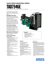 Volvo Penta TAD734GE User manual
-
Volvo Penta IPS 500 User manual
-
Volvo Penta D1-30 User manual
Other documents
-
Kohler 600REOZVB Operating instructions
-
 auto maskin DCU 205 User manual
-
Ingersoll-Rand M150 Users Manual And Maintenance Manual
-
Turbosmart TS-0101-1001 Operating instructions
-
Thomson MEC 310#GENSET CONTROLLER OPTION J-CANBUS J1939 User manual
-
Costa Farms 4PENTBRRED8PK User manual
-
Volvo MD Engine Workshop Manual
-
Precision PW66 User manual
-
Raymarine eci-100 Installation Instructions Manual
-
 auto maskin DCU 305 R3 User manual


