Page is loading ...

SERVING THE GAS INDUSTRY WORLDWIDE
RMG REGEL + MESSTECHNIK GMBH
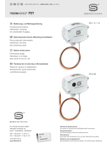
Actuator RMG 672
672.20
Version 04/07
OPERATING AND MAINTENANCE INSTRUCTIONS / SPARE PARTS

Contents Page
1. General information 3
1.1 Safety information 3
2. Specific operating instructions
4
2.1 Opening the safety shut-off valve 4
2.2 Engaging actuators K10a, K11a/1 and K11a/2 4
3. Specific maintenance instructions 4
3.1 Actuators K10a, K11a/1 and K11a/2 4
3.2 Actuation tests 4
3.3 Instructions for testing and adjusting 4
3.4 Tightening torques 5
3.5 Lubricants 5
3.6 Assembling and adjusting tools 5
4. Spare parts
4.1.1 Spare parts drawing actuator K10a 6
for RMG 402, RMG 408 and RMG 721
4.1.2 Spare parts list actuator K10a 7
for RMG 402, RMG 408 and RMG 721
4.2.1 Spare parts drawing actuators K10a, K11a/1 and K11a/2 8
for RMG 503, RMG 530 and RMG 711
4.2.2 Spare parts list actuators K10a, K11a/1 and K11a/2 9
for RMG 503, RMG 530 and RMG 711
4.3.1 Spare parts drawing actuators K12 and K13 10
for RMG 402, RMG 408 and RMG 721
4.3.2 Spare parts list K12 and K13 11
for RMG 402, RMG 408 and RMG 721
4.4.1 Spare parts drawing, accessories for K10a, K11a/1 and K11a/2 12
Assembly on RMG 503, RMG 530 and RMG 711
4.4.2 Spare parts drawing, accessories for K10a, K11a/1 and K11a/2 13
Assembly on RMG 503, RMG 530 and RMG 711
4.5.1 Spare parts drawing, accessories for K10a, K12 and K13 14
Assembly on RMG 402, RMG 408 and RMG 721
4.5.2 Spare parts list, accessories for K10a, K12 and K13 15
Assembly on RMG 402, RMG 408 and RMG 721
4.6 Parts for maintenance purposes 16
672.20 S.02

672.20 S.03
Note
Caution
!
danger of damage to property and/
or the environment
important additional information
Eye catcher used for:
Danger
!
danger to life and limb
1. General information
All persons involved with the assembly, operation and/or maintenance of safety shut-off valves must read
and understand all of the following documents:
- Technical product information contained in valves and controls information sheets, e.g. 711.00.
- General operating manual for gas pressure regulators and safety devices– this RMG document
contains information on assembly and operation as well as general information on troubleshooting.
- Operating and maintenance instructions/ spare parts 672.20– this document contains more detailed
information on assembly and operation of safety shut-off valves.
- Actuator RMG 672 is an integral component of the safety shut-off valve and is described in this document,
"Operating and maintenance instructions, spare parts".
There are national laws and regulations for all sorts of jobs on gas pressure governors, from planning to
maintenance. Be sure to comply. (In Germany, for instance, DVGW work sheets G 600, G 459/II, G 491
and G 495.)
Inspection and maintenance intervals depend mostly on operating conditions and the nature and properties
of the gas. There are no general rules or recommendations for intervals. For Germany, we recommend to
consider maintenance intervals as stated in DVGW work sheet G 495 in a first instance. However, in the
mid-term, intervals must be adapted to the requirements of each specific equipment.
During maintenance, components must be cleaned and then checked thoroughly. This is necessary even if
there have not been any unusual observations during operation and/or functional testing. Checks must focus,
in particular, on diaphragms and seals and all movable parts and their respective bearings. Any and all
defective parts must be replaced with new ones. The same applies to O rings removed during disassembly.
Item numbers mentioned in the specific operating and maintenance instructions correspond with the
numbers in the spare parts lists and drawings.
Some parts in the lists and drawings are marked with a letter "W". We recommend to always have a reserve of
those parts in stock for maintenance purposes. Those spare parts are put together in another separate list at
the end of the spare parts list.
The following actuators are used with the following equipments. For all, there are corresponding operating
and maintenance instructions:
RMG 402 402.20
RMG 408 408.20
RMG 503 DN 25/50 - DN 150/300 503.20
RMG 530 530.20
RMG 711 711.20 and 711.21
RMG 721 721.20
1.1 Safety information
In this manual, safety information is highlighted by means of the following titles and eye catchers:

672.20 S.04
Actuation tests with actuators K10a, K11a/1 and K11a/2 for RMG 503, RMG 530 and RMG 711 may be carried out only
with actuators mounted on shut-off valve switch devices. Otherwise, there is a danger of mechanical damage.
Before starting, remove sealing cap (1) from rod (22).
3.2 Actuation tests
3.3 Instructions for testing and adjusting actuators / switch devices
3.3.1 Actuators K10a, K12 and K13 for RMG 402, RMG 408 and RMG 721
Y
X
Casing
Pressure spring
Adjusting nut
Switching rod
Switch bearing
Switch device
2 mm
Shut-off valve must be engaged. Switching rod must rest on switch bearing. The value of adjustment Y between joining
piece and pressure spring must be equal to gap X (with respect to casing). In the event of deviations, turn adjusting nut
to adjust. The switch rod must be about 2 mm shorter.
2.2 Engaging actuators K10a, K11a/1 and K11a/2
Before dismounting the actuator from the shut-off valve switch device, you must release the actuator.
Devices with underpressure release are released automatically.
If you want to dismount the switch mechanism, you must first initiate the underpressure release
and then pull back the rod (22) at least to its engaging position.
When mounting the switch mechanism, pull back rod (22) and push the lock bushing (12)
over the spheres (28). (Position as in case of underpressure shut-off.)
Rod (22) must move easily. If you should find any damages to the switching face
(dents, burs etc.), replace the rod.
The contact faces between the spring support (8) and lock bushing (12) must be free of grease and oil at all times.
The spheres (28) and their support holes may be greased, but only a very thin layer of grease.
3. Specific maintenance instructions
3.1 Actuators K10a, K11a/1 and K11a/2
•
•
•
NOTE
Caution
!
2. Specific operating instructions
2.1 Opening the safety shut-off valve
The shut-off valve works on the principle of underpressure shut-off. It can be engaged only if the pressure at the measuring point
corresponds to the operating pressure pa.
Actuators K10a, K11a/1 and K11a/2 must engage first.
Unscrew sealing cap (1), turn round and put on rod (22, 50). Pull rod all the way to limit stop and let slip back slowly.
The actuator is engaged. The shut-off valve may be opened now.

Cap
Switching rod
Switch bearing
- The shut-off valve must be engaged.
The cap must have been dismounted.
- The switch rod must not rest on the switch bearing.
- The gap must not be greater than 1 mm max.
Switch bearing
Switch bearing
Cap
Adjusting nut
max. 1 mm
3.5 Lubricants
3.6 Montage und Einstellwerkzeuge
Screws and Tightening torques M
A
in Nm
bolts - Item no.
K10a, K11a/1, K11a/2
K12 K13
Components (cover with thin layer) Lubricant RMG part no.
Thread of spring plate (4, 101, 114)
Tread of sealing cap (1)
Assembly paste 27091
All O rings
Diaphragm support
Slip guides, slip faces and
switching elements
Silicone grease 27081
All fastening screws and screwed
pipe connections
Assembly grease 28267
3.4 Tightening torques M
A
21 20 - -
24 65 - -
111 - 20 20
122 - 20 15
Tools Part no. for item no.
Case A19 DIN 5254 26531 11
Shut-off valve adjusting ke 10004912 4 and 23
Screw driver 14 DIN 911 26266 101
672.20 S. 05
3.3.2 Actuators K10a, K11a/1 and K11a/2 for
RMG 503, RMG 530 and RMG 711 DN 25 thru DN 150
- The shut-off valve must be engaged.
The cap must have been dismounted.
- The gap between switching rod and switch
bearing should be 0.3 ± 0.2. If necessary, adjust
by turning the adjusting nut.
3.3.3 Actuators K10a, K11a/1 and K11a/2
for RMG 711 DN 200 thru DN 300
0,3 ± 0,2
Caution
!
Functional testing
It should not be possible to engage the
actuator after it has been released.

672.20 S. 06
4.1.1 Spare parts drawing actuator K10a
for RMG 402, RMG 408 and RMG 721
Type with high and low
response pressure
26
33
31/32
42
41
1
W 2
3
4
5
6
W 7
8
9
10
11
12
13
14
15
16
17
18
19
20
21
22
23
24
25
26
27
28
29 W
30 W
31/32
33
26
34 W
35
36 W
37
38
39
40
Type with low response
pressure only
Type with high response pressure only
Special design (without diaphragm-break safety device)
M
A
Be sure to comply with tightening torques in table on page 5.
W Parts should be held in stock for maintenance purposes.
M
A
M
A

Item
no. Denomination Number W Material Part no.
672.20 S.07
4.1.2 Spare parts list actuator K10a
for RMG 402, RMG 408 and RMG 721
1 Sealing cap 1 LM 10001789
2 O ring 1
W KG 20244
3 Diaphragm cap 1
LM 10022523
4 Spring plate 1
Ms 10001844
5 Pressure spring for low response pressure, optionally:
5 wire ø 1.1 mm - light blue 1
FSt 10000868
5 wire ø 1.2 mm - white 1
FSt 10001837
5 wire ø 1.4 mm - black 1
FSt 10001760
6 Pressure spring for high response pressure, optionally:
6 wire ø 2.5 mm - yellow 1
FSt 10001838
6 wire ø 3.2 mm - light red 1
FSt 10000866
6 wire ø 3.6 mm - dark red 1
FSt 10000867
6 wire ø 4.75 mm - white 1
FSt 10001839
7 O ring 1
W KG 21069
8 Spring support 1
K 10008563
9 Diaphragm disk 1
St 10010611
10 Pressure disk 1
LM 10004882
11 Sealing ring 1
FSt 19131
12 Lock bushing, complete 1
St/LM/KG 10010619
13 Cheese head screw 3
St 10370
14 Lock washer 3
FSt 14125
15 Guide bush 1
Al/Bz 10001799
16 Pressure spring 1
FSt 10009227
17 Thrust piece 1
LM 10001785
18 Indexing bolt 1
NSt 10001780
19 Bottom, complete 1
LM/Ms 10001736
20 Lock washer 4
FSt 14112
21 Cheese head screw 4
St 10369
22 Rod, complete 1
St/NSt 10001787
23 Spring plate 1
K 10000856
24 Cheese head screw 4
St 10594
25 Lock washer 4
FSt 14114
26 Conical nipple 2
LM 18694
27 On / off valve 1 89190000
28 Sphere 6
St 5108
29 O ring 1
W KG 20518
30 Diaphragm 1
W KG 10010610
31 Union nut 1
St 30804
32 Cutting ring 1
St 30904
33 Connection pipe 1
St 30113
34 O ring 1
W KG 20226
35 Actuator casing 1
LM 10001752
36 O ring 1
W KG 20243
37 Sphere 1
St 26267
38 Pressure spring 1
FSt 10014029
39 Conical nipple 1
LM 18735
40 Sealing cap 1
Ms 10014030
41 Stopping pipe 1
LM 10001784
42 Sealing ring 1
FSt 19182
W Parts should be held in stock for maintenance purposes.
German abbreviations stand for the following materials:
St ... steel LM ... light metal / alloy GMs ... cast brass
NSt ... stainless steel Ms
... brass GZn ... cast zinc
FSt ... spring steel GS
... cast steel AlBz ... aluminium bronze
NFSt ... stainless spring steel GGG
... spheroidal graphite cast iron K ... synthetic materials
Bz ... bronze GBz
... cast bronze KG ... gummous synthetic materials
Cu ... copper GLM
... cast light metal SSt ... foamed materials

672.20 S.08
58
29 W
28
57
56
55
54
35
34 W
33
31/32
26
30 W
27
26
25
24
23
22
17
16
15
14
13
12
11
10
9
8
W 7
6
5
4
3
W 2
1
X
41
33
27
26
31/32
42
W 30
61
W 62
26
31/32
33
71 W
72 W
73
4.2.1 Spare parts drawing actuators K10a, K11a/1 and K11a/2
for RMG503, RMG530 and RMG711
Actuator K10a
Actuator K11a/1
Actuator K11a/2
(for items missing, see K10a)
(for items missing, see K10a)
Ansicht X
M
A
Type with high and low
response pressure
Type with high response
pressure only (K10a and K11a/1
without diaphragm-break safety
device)
Type with low response
pressure only
M
A
Be sure to comply with tightening torques in table on page 5.
W Parts should be held in stock for maintenance purposes.

Item Part no.
no. Denomination Number W Material K10a K11a/1 K11a/2
672.20 S.09
4.2.2 Spare parts list actuators K10a, K11a/1 and K11a/2
for RMG 503, RMG 530 and RMG 711
1 Sealing cap 1 LM 10001789 10001789 10001789
2 O ring 1 W KG 20244 20244 20244
3 Diaphragm cap 1 LM 10022523 10022523 10022523
4 Spring plate 1 Ms 10001844 10001844 10001844
5 Pressure spring for low response pressure, optionally:
5 Wire ø 1.1 mm - light blue 1 FSt 10000868
5 Wire ø 1.2 mm - white 1 FSt 10001837
5 Wire ø 1.4 mm - black 1 FSt 10001760 10001760
5 Wire ø 2.25 mm - fiery red 1 FSt 10001830 10001830
6 Pressure spring for high response pressure, optionally:
6 Wire ø 3.2 mm - light red 1 FSt 10000866 10000866
6 Wire ø 3.6 mm - dark red 1 FSt 10000867 10000867
6 Wire ø 4.75 mm - white 1 FSt 10001839 10001839 10001839
7 O ring 1 W KG 21069 21069 21143
8 Spring support 1 K 10008563 10008563 10008563
9 Diaphragm disk 1 St 10010611
10 Pressure disk 1 LM 10004882 10022516
11 Sealing ring 1 FSt 19131 19187
12 Lock bushing, complete 1 St/LM/KG 10010619 10022512 10022525
13 Cheese head screw 3 St 10370 10370 10370
14 Lock washer 3 FSt 14125 14125 14125
15 Guide bush 1 Al/Bz 10001799 10001799 10001799
16 Pressure spring 1 FSt 10011077 10011077 10011077
17 Thrust piece 1 LM 10022527 10022527 10022527
22 Rod, complete 1 St/NSt 10022504 10022504 10022504
23 Spring plate 1 K 10000856 10000856
23 Spring plate 1 Ms 10001842
24 Cheese head screw 4 St 10594 10594 10594
25 Lock washer 4 FSt 14114 14114 14114
26 Conical nipple 2 LM 18694 18694 18694
27 On / off valve 1 89190000 89190000
28 Sphere 6 St 5108 5108 5108
29 O ring 1 W KG 20518 20518 20518
30 Diaphragm 1 W KG 10010610 10022515
31 Union nut 1 St 30804 30804
31 Union nut 2 St 30804
32 Cutting ring 1 St 30904 30904
32 Cutting ring 2 St 30904
33 Connection pipe 1 St 30113 30113
33 Connection pipe 2 St 30113
34 O ring 1 W KG 21143 21143 21143
35 Actuator casing 1 LM 10022522 10022522 10022522
41 Stopping pipe 1 LM 10001784 10001784 10001794
42 Sealing ring 1 FSt 19182 19182 19182
54 Lever 1 Ms 10022508 10022508 10022508
55 Stud 1 NSt 10022507 10022507 10022507
56 Cheese head screw 2 St 10361 10361 10361
57 Dowel pin 1 FSt 17186 17186 17186
58 Cheese head screw 2 St 10004895 10004895 10004895
61 Intermediate ring 1 LM 10022514
62 O ring 1 W KG 21005
71 O ring 1 W KG 20243
72 O ring 1 W KG 21144
73 Guide ring 1 Al/Bz 10022524

672.20 S.10
4.3.1 Spare parts drawing actuators K12 and K13
for RMG 402, RMG 408 and RMG 721
111
112
113 W
114
115
116
117
118
119 W
120
121
122
100
101
102
103
104
105
106
107
108
109/110
123
124
M
A
Be sure to comply with tightening torques in table on page 5.
W Parts should be held in stock for maintenance purposes.
Actuator K12
Type with low response
pressure only
Type with high response pressure only
(special design)
M
A
M
A
106
W 119
W 132
133
120
Actuator K13
(for items missing, see K12)

Item Part no.
no. Denomination Number W Materials K12 K13
672.20 S.11
4.3.2 Spare parts list K12 and K13
for RMG 402, RMG 408 and RMG 721
no.no.no.no.no.no.no.
100 Cap 1 St 10001777 10001777
101 Adjusting screw 1 Ms 10001776 10001776
102 Actuator casing, complete 1 LM/Ms 10001731 10001731
103 Pressure spring for high response pressure, optionally:
103 Wire ø 5.0 mm - light green 1 FSt 10001820
103 Wire ø 6.3 mm - yellow 1 FSt 10001821 10001821
103 Wire ø 8.0 mm - light red 1 FSt 10001822 10001822
104 Spring plate 1 NSt 10001774 10001774
105 Spring suspension 1 LM 10001773 10001773
106 Diaphragm disk 1 LM 10001750 10001751
107 Conical nipple 1 LM 18842 18842
108 Connection pipe 1 St 30074 30074
109 Union nut 1 St 30804 30804
110 Cutting ring 1 St 30904 30904
111 Hex screw 4 St 10358 10358
112 Lock washer 4 FSt 14122 14122
113 O ring 1 W KG 20308 20308
114 Adjusting screw 1 Ms 10001775 10001775
115 Pressure spring for low response pressure, optionally:
115 Wire ø 2.0 mm - white 1 FSt 10001825 10001825
115 Wire ø 2.8 mm - light blue 1 FSt 10001826 10001826
115 Wire ø 3.6 mm - black 1
FSt 10001827 10001827
116 Deep groove ball thrust bearing 1 St 26268 26268
117 Diaphragm rod 1 NSt 10001746 10001746
118 Sphere 1 St 26267 26267
119 Diaphragm 1 W KG 10001757 10001763
120 Diaphragm cap 1 LM 10001744 10001745
121 Lock washer 4 FSt 14122 14122
122 Cheese head screw 4 St 10351 10351
123 Stopping pipe 1 LM 10001817 10001817
124 Adhesive disk 1 KG 10001818 10001818
132 O ring 1 W KG 20307
133 Diaphragm support 1 LM 10001772

672.20 S.12
155 156 157
158 159
150 151 152 153
4.4.1 Spare parts drawing, accessories for actuators K10a, K11a/1 and K11a/2
Assembly on RMG 503, RMG 530 and RMG 711 DN 25 thru DN 150
Assembly on RMG 711 DN 200 thru DN 300

Item
no. Denomination Number W Material Part no.
672.20 S.13
4.4.2 Spare parts drawing, accessories for actuators K10a, K11a/1 and K11a/2
Assembly on RMG 503, RMG 530 and RMG 711
Assembly on RMG 503, RMG 530 and RMG 711 DN 25 thru DN 150
150 Lock washer 1
FSt 19101
151 Pressure spring 1 FSt 10017639
152 Joining piece, complete, optionally for:
152 RMG 503 DN 25/50 and DN 50/100 1 LM/Ms 10022545
152 RMG 530DN 50/100 1 LM/Ms 10022545
152 RMG 711 DN 25 and DN 50 1 LM/Ms 10022545
152 RMG 503 DN 80/150 and DN 100/200 1 LM/Ms 10022550
152 RMG 530 DN 80/150 and DN 100/200 1 LM/Ms 10022550
152 RMG 711 DN 80 and DN 100 1 LM/Ms 10022550
152 RMG 503 DN 150/300 1 LM/Ms 10022555
152 RMG 711 DN 150 1 LM/Ms 10022555
153 Switching rod optionally for:
153 RMG 503 DN 25/50 and DN 50/100 1 NSt 10022543
153 RMG 530DN 50/100 1 NSt 10022543
153 RMG 711 DN 25 and DN 50 1 NSt 10022543
153 RMG 503 DN 80/150 and DN 100/200 1 NSt 10022548
153 RMG 530 DN 80/150 and DN 100/200 1 NSt 10022548
153 RMG 711 DN 80 and DN 100 1 NSt 10022548
153 RMG 503 DN 150/300 1 NSt 10022553
153 RMG 711 DN 150 1 NSt 10022553
Assembly on RMG 711 DN 200 thru DN 300
155 Pressure spring 1 FSt 10017639
156 Joining piece, complete 1 LM/Ms 10030202
157 Switching rod 1 NSt 10030204
158 Adjusting nut 1 Ms 10030205
159 Hex nut 1 St 13046

4.5.1 Spare parts drawing, accessories for actuators K10a, K12 and K13
Assembly on RMG 402, RMG 408 and RMG 721
160 161 162 163 164 165 166 167 168 169 170
W W
672.20 S. 14
W Parts should be held in stock for maintenance purposes.

Item
no. Denomination Number W Material Part no.
672.20 S.15
4.5.2 Spare parts list, accessories for actuators K10a, K12 and K13
Assembly on RMG 402, RMG 408 and RMG 721
160 Cheese head screw 2 St 10550
161 Lock washer 2 St 14123
162 Pressure spring 1 FSt 10001831
163 Hex nut 1
St 13046
164 O ring 1 W KG 20235
165 Headless pin (setscrew) 1 St 8486
166 Joining piece 1 St 10001810
167 O ring 1 W KG 20310
168 Guide screw 1 NSt 10001811
169 Switching rod 1 NSt 10001812
Only for actuators K12 and K13 with underpressure release
170 On / off valve 1 89190100

672.20 S.16
4.6 Parts for maintenance purposes
Item Part no.
no. Denomination K12 K13
Actuators K12 and K13 for RMG 402, RMG 408 and RMG 721
113 O ring 20308 20308
119 Diaphragm 10001757 10001763
132 O ring 20307
Item
no. Denomination Part no.
Actuators K10a for RMG 402, RMG 408 and RMG 721
2 O ring 20244
7 O ring 21069
29 O ring 20518
30 Diaphragm 10010610
34 O ring 20226
36 O ring 20243
Item Part no.
no. Denomination K10a K11a/1 K11a/2
Actuators K10a, K11a/1 and K11a/2 for RMG 503, RMG 530 and RMG 711
2 O ring 20244 20244 20244
7 O ring 21069 21069 21143
29 O ring 20518 20518 20518
30 Diaphragm 10010610 10022515
34 O ring 21143 21143 21143
62 O ring 21005
71 O ring 20243
72 O ring 21144
Item
no. Denomination Part no.
Accessories for actuators K12 and K13
Assembly on RMG 402, RMG 408 and RMG 721
164 O ring 20235
167 O ring 20310
/