
GB
0459 560 101 GB 070309
MXLt 150v, MXLt 200,
MXLt 270, MXLt 340
Instruction manual

-- 2 --
www2
SE Ytterligare språk av bruksanvisningen och reservdelsförteckning finns tillgängligt
på internetadressen www.esab.com
DK Du kan finde yderligere sprogversioner af brugsanvisningen og reservedelsfor-
tegnelsen på internet-- adressen www.esab.co m
NO Du finner flere språkversjoner av bruksanvisningen samt reservdelsliste på
Internett-- adressen www.esab.com
FI Muilla kielillä olevia käyttöohjeita ja varaosaluetteloita löydät Internet--sivuiltamme
www.esab.com
GB The instructions and the spare parts list are available in other languages on the
Internet at www.esab.com
DE Weitere Sprachversionen von Betriebsanweisung und Ersatzteilverzeichnis
finden Sie im Internet unter www.esab.com.
FR Les instructions et la liste des pièces de rechange sont disponibles dans
d’autres langues sur le site www.esab.com.
NL Op www.esab.com vindt u de instructies en de lijsten met reserveonderdelen in
andere talen.
PT As instruções e a lista de peças sobressalentes estão disponíveis noutras
línguas na Internet em www.esab.com
ES Las instrucciones y las listas de repuestos están disponibles en otros idiomas en
Internet, en la dirección www.esab.com
IT Le istruzioni e l’elenco dei pezzi di ricambio sono disponibili in altre lingue su
Internet all’indirizzo www.esab.com
PL Instrukcja i lista czê¶ci zamiennych s± dostêpne w innych wersjach jêzykowych w
Internecie w witrynie www.esab.com
CZ Pokyny a seznam náhradních dílù v jiných jazycích jsou k dispozici na Internetu na
adrese www.esab.com
HU Az utasítások és a pótalkatrészlista más nyelveken elérhetõ az interneten a
www.esab.com honlapon.
Svenska 0459 560 101 SE Norsk 0459 560 101 NO
Dansk 0459 560 101 DK Soumi 0459 560 101 FI
English 0459 560 101 GB Deutsch 0459 560 101 DE
Français 0459 560 101 FR Nederlands 0459 560 101 NL
Español 0459 560 101 ES Italiano 0459 560 101 IT
Português 0459 560 101 PT Polski 0459 560 101 PL
Česky 0459 560 101 CZ Magyar 0459 560 101 HU

-- 3 --
TOCe
Rights reserved to alter specifications without notice.
1 DIRECTIVE 4........................................................
2SAFETY 4...........................................................
3 INTRODUCTION 5...................................................
4 SHIPMENT AND PACKAGING 5.......................................
5 TECHNICAL DATA 6.................................................
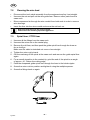
6 OPERATION 7.......................................................
6.1 Fitting the liner 7............................................................
6.2 Assembling the swan neck 7..................................................
6.3 Fitting the central adaptor assembly to the equipment 8..........................
6.4 Setting the level of shielding gas 8.............................................
6.5 Checklist 8.................................................................
6.6 Changing wire 8.............................................................
7 MAINTENANCE 8....................................................
7.1 Cable assembly 8...........................................................
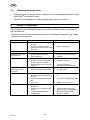
7.2 Cleaning the wire feed 9.....................................................
7.3 Spiral liner / PTFE liner 9.....................................................
7.4 Cleaning the swan neck 10....................................................
8 FAULT--TRACING 10..................................................
9 DISASSEMBLY AND DISPOSAL 11.....................................
10 IN THE EVENT OF AN EMERGENCY 11.................................
11 ORDERING OF SPARE PARTS 11......................................
ORDERING NUMBER 13.................................................
SPARE PARTS LIST 14...................................................
WEAR PARTS 16........................................................

-- 4 --
bg13d2e
1DIRECTIVE
DECLARATION OF CONFORMITY
ESAB AB, Welding Equipment, SE--695 81 Laxå, Sweden, gives its unreserved guarantee that the
welding torch/welding gun MXL 150v, MXL 200, MXL 270, MXL 340 are constructed and tested
in compliance with the standard EN 60974--7 in accordance with the requirements of directive
(2006/95/EC).
-- -- -- -- -- -- -- -- -- -- -- -- -- -- -- -- -- -- -- -- -- -- -- -- -- -- -- -- -- -- -- -- -- -- -- -- -- -- -- -- -- -- -- -- -- -- -- -- -- -- -- -- -- -- -- -- -- -- -- -- -- -- -- --------
Kent Eimbrodt
Global Director
Equipment and Automation
Laxå 2007--03--08
2SAFETY
Users of ESAB welding equipment have the ultimate responsibility for ensuring that anyone who
works on or near the equipment observes all the relevant safety precautions. Safety precautions
must meet the requirements that apply to this type of welding equipment. The following recommen-
dations should be observed in addition to the standard regulations that apply to the workplace.
All work must be carried out by trained personnel well--acquainted with the operation of the welding
equipment. Incorrect operation of the equipment may lead to hazardous situations which can result
in injury to the operator and damage to the equipment.
1. Anyone who uses the welding equipment must be familiar with:
S its operation
S location of emergency stops
S its function
S relevant safety precautions
S welding
2. The operator must ensure that:
S no unauthorized person is stationed within the working area of the equipment when it is
started up.
S no--one is unprotected when the arc is struck
3. The workplace must:
S be suitable for the purpose
S be free from drafts
4. Personal safety equipment
S Always wear recommended personal safety equipment, such as safety glasses, flame--proof
clothing, safety gloves.
S Do not wear loose--fitting items, such as scarves, bracelets, rings, etc., which could become
trapped or cause burns.
5. General precautions
S Make sure the return cable is connected securely.
S Work on high voltage equipment may only be carried out by a qualified electrician.
S Appropriate fire extinquishing equipment must be clearly marked and close at hand.
S Maintenance must not be carried out on the equipment during operation.
GB

-- 5 --
bg13d2e
WARNING
READ AND UNDERSTAND THE INSTRUCTION MANUAL BEFORE INSTALLING OR OPERATING.
ARC WELDING AND CUTTING CAN BE INJURIOUS TO YOURSELF AND OTHERS. TAKE PRECAU-
TIONS WHEN WELDING. ASK FOR YOUR EMPLOYER’S SAFETY PRACTICES WHICH SHOULD BE
BASED ON MANUFACTURERS’ HAZARD DATA.
ELECTRIC SHOCK -- Can kill
S Install and earth the welding unit in accordance with applicable standards.
S Do not touch live electrical parts or electrodes with bare skin, wet gloves or wet clothing.
S Insulate yourself from earth and the workpiece.
S Ensure your working stance is safe.
FUMES AND GASES -- Can be dangerous to health
S Keep your head out of the fumes.
S Use ventilation, extraction at the arc, or both, to take fumes and gases away from your breathing zone
and the general area.
ARC RAYS -- Can injure eyes and burn skin.
S Protect your eyes and body. Use the correct welding screen and filter lens and wear protective
clothing.
S Protect bystanders with suitable screens or curtains.
FIRE HAZARD
S Sparks (spatter) can cause fire. Make sure therefore that there are no inflammable materials nearby.
NOISE -- Excessive noise can damage hearing
S Protect your ears. Use earmuffs or other hearing protection.
S Warn bystanders of the risk.
MALFUNCTION -- Call for expert assistance in the event of malfunction.
PROTECT YOURSELF AND OTHERS!
ESAB can p rovide you with all necessary weldin g p rotection an d accesso ries.
3 INTRODUCTION
The MIG / MAG welding torches of this series are exclusively intended for shielded--
arc welding using inert gas (MIG) or active gas (MAG) for industrial and commercial
use by suitably trained employees. The torches are only available in manual
versions.
4 SHIPMENT AND PACKAGING
The components are carefully checked and packaged however damage may occur
during shipping.
Checking procedure on receipt of goods
• Check that the shipment is correct by referring to the shipping note.
In case o f damage
• Check the package and components for damage (visual inspection).
In case of co mplaints
If the package and/or components have been damaged during shipment:
S Contact with the last carrier immediately.
S Keep the packaging (for possible inspection by the carrier or supplier, or for
returningn the goods).
GB

-- 6 --
bg13d2e
Storage in an enclosed sp ace
Ambient temperature
-- for shipment and storage: -- 25 °Cto+55°C
Relative air humidity: up to 90% at a temperature of 20 °C
5 TECHNICAL DATA
Weldin g t orch MXL 150v MXL 200 MXL 270 MXL 340
Type of cooling Air Air Air Air
Permitted load
at 20% intermittence *
Carbon dioxide CO
2
150 A
Mixed gas Ar/CO
2
150 A
Permitted load
at 35% intermittence *
Carbon dioxide CO
2
120 A 200 A 270 A 340 A
Mixed gas Ar/CO
2
120 A 170 A 260 A 320 A
Recommended gas flow 8--15l/min 10--18 l/min 10--18 l/min 10--20 l/min
Max pressure 2.5 bar
Wire diameter 0.6--0.8 mm 0.6--1.0 mm 0.8--1.2 mm 0.8--1.2 mm
Weight
2.5 m hose package
1.1 kg -- -- --
3.0 m hose package -- 1.6 kg 2.2 kg 2.6 kg
4.0 m hose package -- 2.0 kg 2.6 kg 3.7 kg
Cable assembly
Standard length
2.5 m 3.0 m / 4.0 m 3.0 m / 4.0 m 3.0 m / 4.0 m
Standard--control cable 2--pole 2--pole 2--pole 2--pole
* The capacity my be reduced up to 30% when pulse welding.
Duty cycle
The duty cycle refers to the time as a percentage of a ten--minute period that you can weld at a
certain current without overheating.
General torch data with reference to IEC/EN 60 974--7
T ype of voltage: DC voltage
Wire type: Standard round wire
Voltage measurement: Peak value of 113V
Connection protection
Machine side (EN 60 529):
IP3X
Shielding gas: CO
2
or Ar/CO
2
GB

-- 7 --
bg13d2e
6 OPERATION
General safety regulations for the handling of the equipment can be found on
page 4. Read them before you start using the equipment!
WARNING!
This product is intended for industrial use. In a domestic environment this product may cause radio
interference. It is the user’s responsibility to take adequate precautions.
MXL welding torches can be used in any welding position.
The torch switch in the MXL handle is suitable for 42 V, maximum 1 A.
6.1 Fitting the liner
Fit the correct wire guide liner for the application, as needed to suit the wire type and
diameter, see 7.3.
For information on how to install new liners and about correct assembly
procedure, see the chapter entitled “Maintenance”
Spiral liner = for steel wires
PTFE--liner = for aluminium, copper, nickel and stainless steel wires
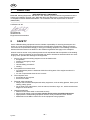
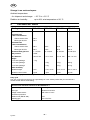
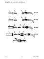
6.2 Assembling the swan neck
The following figures indicate how to assemble the different welding torch types.
MXL 150v
MXL 200
MXL 270
MXL 340
1. Gas nozzle 2. Contact tip 3. Nozzle spring 4. Tip adaptor 5. Gas diffusor
GB

-- 8 --
bg13d2e
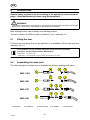
6.3 Fitting the central adaptor assembly to the equipment
1. Check that the wire guide liner is fitted correctly.
2. Insert the central plug into the socket on the wire feed unit and secure it by
tightening the adaptor nut firmly.
6.4 Setting the level of shielding gas
Set the quantity of gas required on the gas regulator. The type and quantity of gas to
be used depend on the welding task to be performed.
6.5 Checklist
S Check the cable assembly before connecting it to the wire feed unit to confirm
the wire liner is suitable for the wire diameter and type .
S Check the fixed end consumable parts on the swan neck, whether the correct
contact tip etc. is being used for the wire diameter and type.
6.6 Changing wire
S When changing the wire, ensure that the end of the wire is deburred.
S Insert the wire into the wire feeding unit in accordance with the operating
instructions.
S When inserting the wire, press the wire jog button on the wire feed unit.
7 MAINTENANCE
Regular maintenance is important for safe, reliable operation.
Weldin g t orch
S Cleaning and replacement of the welding torch’s wear parts should take place
at regular intervals in order to achieve trouble--free wire feed. Blow the wire
guide clean regularly and clean the contact tip.
Before carrying out cleaning, servicing and repair work, the following
shutdown procedure must be followed.
1. Switch off the power supply.
2. Close off the gas supply.
Make sure that the power supply and gas remain turned off all the time while
servicing the machine.
7.1 Cable assembly
S Check that all the nuts are tight.
S Replace the liner if it is worn or dirty.
S Replace damaged, deformed or worn parts.
GB

-- 9 --
bg13d2e
7.2 Cleaning the wire feed
S Disconnect the torch cable assembly from the equipment and lay it out straight.
S Unscrew the nut and pull out the wire guide liner. Remove other parts from the
swan neck.
S Blow compressed air through the wire conduit from both ends in order to remove
wire shavings.
S Insert the liner into the wire conduit and screw the nut back on.
New liners must be cut to the correct length.
Please follow the following tips and suggestions:
7.3 Spiral liner / PTFE liner
1. Unscrew all the fittings from the swan neck.
2. Unscrew the union nut on the central plug.
3. Remove the old liner, and then push the guide spiral liner through the hose as
far as it will go.
Make sure the cable is stretched out more or less straight.
4. Tighten the union nut by hand.
5. Cut the overhang off the spiral at the swan neck and remove the guide spiral liner
again.
6. For a smooth transition to the contact tip, grind the end of the spiral to an angle
of approx. 40°. Deburr the cutting edge.
7. Push the sharpened guide spiral liner through the hose to the holder nipple.
8. Screw the union nut into position and tighten it using the multiple spanner.
9. Screw the fittings back on again.
GB

-- 1 0 --
bg13d2e
7.4 Cleaning the swan neck
S Clean the inside of the gas nozzle regularly to remove welding spatter and spray
with ESAB
®
anti--spatter agent.
S Check the consumables for visible damage and replace if necessary.
8 FAULT--TRACING
If the measures described below are not successful, please consult your dealer or
the manufacturer.
Please also read the operating instructions for the welding components, e.g. power
source and wire feed unit.
Problem Cause Solution
Torch becomes too hot S Contact tip / Collets not tight
enough
S Current connections on the
torch side and to the work piece
are loose
S Check and tighten
S Check and tighten
No switch function S Control line interrupted / faulty S Check / Repair
Wire burnt back onto
the contact tip
S Wrong parameter setting
S Worn contact tip
S Check or correct the setting
S Replace
Irregular wire feed S Liner blocked
S Contact tip and wire diameter
do not match one another
S Wrong tension set on the wire
feed unit
S Blow through in both directions
S Replace contact tip
S Correct according to
manufacturer’s instructions
Short arc between the
gas nozzle and the
work piece
S Spatter bridge between the
contact tip and the gas nozzle
S Clean and spray the inside of
the gas nozzle
Variable arc S Contact tip does not match the
wire diameter, or the contact tip
is worn
S Incorrect welding parameters
set
S Liner worn
S Check and replace the contact
tip
S Correct the welding parameters
S Replace the wire guide
Porous welds S Large amount of spatter in the
gas nozzle
S Insufficient or total lack of gas
shield
S Draught is disturbing the
shielding gas
S Clean the gas nozzle
S Check contents of the gas
bottle and the pressure setting
S Shield welding area with
protective screens
GB

-- 11 --
bg13d2e
9 DISASSEMBLY AND DISPOSAL
Do not dispose of electrical equipment together with normal waste!
In observance of European Directive 2002/96/EC on Waste Electrical and Electronic
Equipment and its implementation in accordance with national law, electrical equipment
that has reached the end of its life must be collected separately and returned to an
environmentally compatible recycling facility. As the owner of the equipment, you should
get information on approved collection systems from our local representative.
By applying this European Directive you will improve the environment and human health!
The welding torch system is mainly made from steel, plastics and non--ferrous me tal,
and must be disposed of in accordance with local environmental regulations.
10 IN THE EVENT OF AN EMERGENCY
In the event of an emergency, the power supply must be switched off immediately.
For further action in such circumstances, consult the ‘Power source’ Instruction
manual.
11 ORDERING OF SPARE PARTS
MXL 150v, MXL 200, MXL 270, MXL 340 is designed and tested in accordance with the
international and European standards IEC--/EN 60974--7 It is the obligation of the ser-
vice unit which has carried out the service or repair work to make sure that the product
still conforms to the said standard.
Spare parts may be ordered through your nearest ESAB dealer, see the last page of
this publication.
GB

-- 1 2 --
p

MXLt 150v, MXLt 200, MXLt 270, MXLt 340
Edition 070309
Ordering number
-- 1 3 --
bg13or
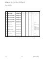
Ordering Number
Ordering no. Type Description Notes
0700 200 001 MXLt 150v Welding torch 2.5 m with fixed connection
0700 200 002 MXLt 200 Welding torch 3.0 m EURO Connection
0700 200 003 MXLt 200 Welding torch 4.0 m EURO Connection
0700 200 004 MXLt 270 Welding torch 3.0 m EURO Connection
0700 200 005 MXLt 270 Welding torch 4.0 m EURO Connection
0700 200 006 MXLt 340 Welding torch 3.0 m EURO Connection
0700 200 007 MXLt 340 Welding torch 4.0 m EURO Connection

MXLt 150v, MXLt 200, MXLt 270, MXLt 340
Edition 070309
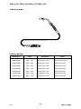
Spare p arts list
-- 1 4 --
bg13sp
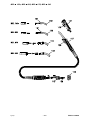
Pos
Denomination Ordering no. MXL150v MXL 200 MXL 270 MXL 340 Notes
101 Head insulator 0700 200 096
x x
102 Swan neck Standard 0700 200 050
x
103 Swan neck Standard 0700 200 051
x
104 Swan neck Standard 0700 200 052
x
105 Swan neck Standard 0700 200 053
x
106 T rigger 2 pol 0700 200 077
x MXL 150v
106 T rigger 2 pol 0700 200 095
x x x MXL 200/ 270/ 340
107 Handle complete 0700 200 093
x MXL 150v
Incl trigger pos 106
107 Handle complete 0700 200 094
x x x MXL 200/ 270/ 340
Incl trigger pos 106
108 Adaptor nut complete 0700 200 097
x x x
109 Liner lock nut 0700 200 098
x x x M10x1
110 Central connector 0700 200 101
x x x Incl. control leads

MXLt 150v, MXLt 200, MXLt 270, MXLt 340
Edition 070309
-- 1 5 --
bg13sp

MXLt 150v, MXLt 200, MXLt 270, MXLt 340
Edition 070309
Wear parts
-- 1 6 --
bg13we
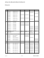
Pos Denomination MXL150v MXL 200 MXL 270 MXL 340
1
Gas nozzle standard Ø 12 mm 0700 200 054 0700 200 054
Gas nozzle standard Ø 15 mm 0700 200 055
Gas nozzle standard Ø 16 mm 0700 200 056
Gas nozzle straight Ø 16 mm 0700 200 057 0700 200 057
Gas nozzle straight Ø 18 mm 0700 200 058
Gas nozzle straight Ø 19 mm 0700 200 059
Gas nozzle conical Ø 9.5 mm 0700 200 060 0700 200 060
Gas nozzle conical Ø 11.5 mm 0700 200 061
Gas nozzle conical Ø 12 mm 0700 200 062
2
Contact tip Cu W0.6 M6x25 0700 200 063 0700 200 063
Contact tip Cu W0.8 M6x25 0700 200 064 0700 200 064
Contact tip Cu W0.9 M6x25 0700 200 065 0700 200 065
Contact tip Cu W1.0 M6x25 0700 200 066 0700 200 066
Contact tip Cu W0.8 M6x28 0700 200 068 0700 200 068
Contact tip Cu W0.9 M6x28 0700 200 069 0700 200 069
Contact tip Cu W1.0 M6x28 0700 200 070 0700 200 070
Contact tip Cu W1.2 M6x28 0700 200 071 0700 200 071
3
Nozzle spring 0700 200 078 0700 200 078
Nozzle spring 0700 200 079
4
Tip adaptor M6 MXL 150v 0700 200 076
Tip adaptor M6, Alu MXL 200 0700 200 067
Tip adaptor M6 MXL 200 0700 200 072
Tip adaptor M6, 35 mm MXL 270 0700 200 073
Tip adaptor M6, 28 mm MXL 340 0700 200 074
Tip adaptor M6, 32 mm MXL 340 0700 200 075
5
Gas diffusor white 0700 200 080
6
Steel liner W0.6 -- W0.8 2.5 m 0700 200 099
Steel liner W0.6 -- W0.8 3.0 m 0700 200 085 0700 200 085 0700 200 085
Steel liner W0.6 -- W0.8 4.0 m 0700 200 086 0700 200 086 0700 200 086
Steel liner W0.9 -- W1.2 3.0 m 0700 200 087 0700 200 087 0700 200 087
Steel liner W0.9 -- W1.2 4.0 m 0700 200 088 0700 200 088 0700 200 088
PTFE liner W0.6 -- W0.8 3.0 m 0700 200 089 0700 200 089 0700 200 089
PTFE liner W0.6 -- W0.8 4.0 m 0700 200 090 0700 200 090 0700 200 090
PTFE liner W0.9 -- W1.2 3.0 m 0700 200 091 0700 200 091 0700 200 091
PTFE liner W0.9 -- W1.2 4.0 m 0700 200 092 0700 200 092 0700 200 092

MXLt 150v, MXLt 200, MXLt 270, MXLt 340
Edition 070309
-- 1 7 --
bg13we

-- 1 8 --
p

-- 1 9 --
p

ESAB AB
SE--695 81 LAXÅ
SWEDEN
Phone +46 584 81 000
www.esab.com
070514
ESAB subsidiaries and representative offices
Europe
AUSTRIA
ESAB Ges.m.b.H
Vienna--Liesing
Tel: +43 1 888 25 11
Fax: +43 1 888 25 11 85
BELGIUM
S.A. ESAB N.V.
Brussels
Tel: +32 2 745 11 00
Fax: +32 2 745 11 28
THE CZECH REPUBLIC
ESAB VAMBERK s.r .o.
Vamberk
Tel: +420 2 819 40 885
Fax: +420 2 819 40 120
DENMARK
Aktieselskabet ESAB
Herlev
Tel:+4536300111
Fax:+4536304003
FINLAND
ESAB Oy
Helsinki
Tel: +358 9 547 761
Fax: +358 9 547 77 71
FRANCE
ESAB France S.A.
Cergy Pontoise
Tel:+33130755500
Fax:+33130755524
GERMANY
ESAB GmbH
Solingen
Tel: +49 212 298 0
Fax: +49 212 298 218
GREAT BRITAIN
ESAB Group (UK) Ltd
Waltham Cross
Tel: +44 1992 76 85 15
Fax: +44 1992 71 58 03
ESAB Automation Ltd
Andover
Tel: +44 1264 33 22 33
Fax: +44 1264 33 20 74
HUNGARY
ESAB Kft
Budapest
Tel:+3612044182
Fax:+3612044186
ITALY
ESAB Saldatura S.p.A.
Mesero (Mi)
Tel:+3902979681
Fax:+390297289181
THE NETHERLANDS
ESAB Nederland B.V.
Amersfoort
Tel: +31 33 422 35 55
Fax: +31 33 422 35 44
NORWAY
AS ESAB
Larvik
Tel:+4733121000
Fax:+4733115203
POLAND
ESAB Sp.zo.o.
Katowice
Tel: +48 32 351 11 00
Fax: +48 32 351 11 20
PORTUGAL
ESAB Lda
Lisbon
Tel: +351 8 310 960
Fax: +351 1 859 1277
SLOVAKIA
ESAB Slovakia s.r.o.
Bratislava
Tel:+421744882426
Fax:+421744888741
SPAIN
ESAB Ibérica S.A.
Alcalá de Henares (MADRID)
Tel: +34 91 878 3600
Fax: +34 91 802 3461
SWEDEN
ESAB Sverige AB
Gothenburg
Tel:+4631509500
Fax:+4631509222
ESAB international AB
Gothenburg
Tel:+4631509000
Fax:+4631509360
SWITZERLAND
ESAB AG
Dietikon
Tel: +41 1 741 25 25
Fax: +41 1 740 30 55
North and South America
ARGENTINA
CONARCO
Buenos Aires
Tel: +54 11 4 753 4039
Fax: +54 11 4 753 6313
BRAZIL
ESAB S.A.
Contagem--MG
Tel: +55 31 2191 4333
Fax: +55 31 2191 4440
CANADA
ESAB Group Canada Inc.
Missisauga, Ontario
Tel: +1 905 670 02 20
Fax: +1 905 670 48 79
MEXICO
ESAB Mexico S.A.
Monterrey
Tel: +52 8 350 5959
Fax: +52 8 350 7554
USA
ESAB Welding & Cutting Products
Florence, SC
Tel: +1 843 669 44 11
Fax: +1 843 664 57 48
Asia/Pacific
CHINA
Shanghai ESAB A/P
Shanghai
Tel: +86 21 5308 9922
Fax: +86 21 6566 6622
INDIA
ESAB India Ltd
Calcutta
Tel: +91 33 478 45 17
Fax: +91 33 468 18 80
INDONESIA
P.T. ESABindo Pratama
Jakarta
Tel: +62 21 460 0188
Fax: +62 21 461 2929
JAPAN
ESAB Japan
Tokyo
Tel: +81 3 5296 7371
Fax:+81352968080
MALAYSIA
ESAB (Malaysia) Snd Bhd
Selangor
Tel: +60 3 8027 9869
Fax:+60380274754
SINGAPORE
ESAB Asia/Pacific Pte Ltd
Singapore
Tel:+6568614322
Fax: +65 6861 31 95
SOUTH KOREA
ESAB SeAH Corporation
Kyungnam
Tel: +82 55 269 8170
Fax: +82 55 289 8864
UNITED ARAB EMIRATES
ESAB Middle East FZE
Dubai
Tel: +971 4 887 21 11
Fax: +971 4 887 22 63
Representative offices
BULGARIA
ESAB Representative Office
Sofia
Tel/Fax: +359 2 974 42 88
EGYPT
ESAB Egypt
Dokki--Cairo
Tel: +20 2 390 96 69
Fax: +20 2 393 32 13
ROMANIA
ESAB Representative Office
Bucharest
Tel/Fax: +40 1 322 36 74
RUSSIA
LLC ESAB
Moscow
Tel: +7 095 543 9281
Fax: +7 095 543 9280
LLC ESAB
St Petersburg
Tel: +7 812 336 7080
Fax: +7 812 336 7060
Distributors
For addresses and phone
numbers to our distributors in
other countries, please visit our
home page
www.esab.com
-
 1
1
-
 2
2
-
 3
3
-
 4
4
-
 5
5
-
 6
6
-
 7
7
-
 8
8
-
 9
9
-
 10
10
-
 11
11
-
 12
12
-
 13
13
-
 14
14
-
 15
15
-
 16
16
-
 17
17
-
 18
18
-
 19
19
-
 20
20


Ask a question and I''ll find the answer in the document
Finding information in a document is now easier with AI
Related papers
-
ESAB ESAB MX Torches User manual
-
ESAB MXA253 B 3m Torch & MXA254 B 4m Torch Specification
-
ESAB MXL™ 200 User manual
-
-
-
ESAB Caddy Mig C160i User manual
-
ESAB MXH 300 PP / MXH 400w PP - MXH 400w PP User manual
-
-
-

