!
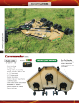
Cover photo may show optional equipment
not supplied with standard unit.
© Copyright 2007 Printed
Read the Operator’s manual entirely. When
you see this symbol, the subsequent
instructions andwarnings are serious - follow
without exception. Your life and the lives of
others depend on it!
Table of Contents
21416
12/17/07
312-849M
Operator’s Manual
RCR1860 and RCR1872 Series
Rotary Cutters

Land Pride
Table of Contents
RCR1860 and RCR1872 Series Rotary Cutters 312-849M
12/17/07
© Copyright 2007 All rights Reserved
Land Pride provides this publication “as is” without warrantyof any kind, eitherexpressedor implied.While every precautionhas beentaken in the preparation ofthis manual, Land
Pride assumesnoresponsibilityfor errorsoromissions.Neitheris anyliabilityassumed fordamagesresultingfromthe use oftheinformation containedherein. Land Pride reserves
the rightto reviseandimprove itsproductsas it seesfit.This publicationdescribes thestateof this productatthe time ofitspublication,andmay notreflect the productinthefuture.
Land Pride is aregistered trademark.
All other brands and product names are trademarks or registered trademarks oftheir respective holders.
Printed in the UnitedStates of America.
Important Safety Information . . . . . . . . . . .1
Safety at All Times . . . . . . . . . . . . . . . . . . . . . . . . . 1
Look For The Safety Alert Symbol . . . . . . . . . . . . .1
Safety Labels . . . . . . . . . . . . . . . . . . . . . . . . . . . . . 4
Introduction . . . . . . . . . . . . . . . . . . . . . . . .7
Application . . . . . . . . . . . . . . . . . . . . . . . . . . . . . . . 7
Using This Manual . . . . . . . . . . . . . . . . . . . . . . . . . 7
Terminology: . . . . . . . . . . . . . . . . . . . . . . . . . . . 7
Definitions: . . . . . . . . . . . . . . . . . . . . . . . . . . . . 7
Owner Assistance . . . . . . . . . . . . . . . . . . . . . . . . . 7
Serial Number Plate . . . . . . . . . . . . . . . . . . . . .7
Further Assistance . . . . . . . . . . . . . . . . . . . . . . 7
Section 1: Assembly and Set-Up . . . . . . . .8
Tractor Requirements . . . . . . . . . . . . . . . . . . . . . . 8
Dealer Assembly . . . . . . . . . . . . . . . . . . . . . . . . . . 8
RCR1872 Tailwheel A-Frame . . . . . . . . . . . . . .8
RCR1860 & RCR1872 . . . . . . . . . . . . . . . . . . .8
Gearbox Vent Plug . . . . . . . . . . . . . . . . . . . . . .9
Tractor Hook-Up . . . . . . . . . . . . . . . . . . . . . . . . . . 9
Driveline Installation . . . . . . . . . . . . . . . . . . . . . . . 10
Driveline Minimum Length . . . . . . . . . . . . . . . .10
Driveline Maximum Allowable Length . . . . . . . 11
Section 2: Optional Equipment Set-Up . .12
Front Guards . . . . . . . . . . . . . . . . . . . . . . . . . . . . 12
Front Chain Guard Installation . . . . . . . . . . . .12
Front Rubber Guard Installation . . . . . . . . . . . 12
Rear Guards . . . . . . . . . . . . . . . . . . . . . . . . . . . . 12
Rear Metal Guard Removal . . . . . . . . . . . . . . . 12
Rear Chain Guard Installation . . . . . . . . . . . . . 13
Rear Rubber Guard installation . . . . . . . . . . . . 13
Section 3: Adjustments . . . . . . . . . . . . . .14
Deck Leveling & Height Adjustments . . . . . . . . . .14
Deck Leveling From Left to Right . . . . . . . . . . . . .14
Deck Cutting Height . . . . . . . . . . . . . . . . . . . . . . . 14
Center 3-Point Link Length . . . . . . . . . . . . . . . . . 15
Tailwheel Height Adjustment . . . . . . . . . . . . . . . . 15
Section 4: Operating Instructions . . . . . .16
Operating Check List . . . . . . . . . . . . . . . . . . . . . .16
Transporting . . . . . . . . . . . . . . . . . . . . . . . . . . . . .16
Un-hooking the Rotary Cutter . . . . . . . . . . . . . . . .16
Cutting Instructions . . . . . . . . . . . . . . . . . . . . . . .17
General Operating Instructions . . . . . . . . . . . . . .17
Section 5: Maintenance and Lubrication 19
Maintenance . . . . . . . . . . . . . . . . . . . . . . . . . . . .19
Service Cutter Blades . . . . . . . . . . . . . . . . . . . . .19
Shearbolt Protected Drivelines . . . . . . . . . . . . . . .20
Slip-Clutch Protected Drivelines . . . . . . . . . . . . . .20
Clutch Run-In . . . . . . . . . . . . . . . . . . . . . . . . . . . .20
Clutch Assembly and Disassembly . . . . . . . . . . .21
Cutter Storage . . . . . . . . . . . . . . . . . . . . . . . . . . .21
Lubrication . . . . . . . . . . . . . . . . . . . . . . . . . . . . . .22
Gauge Wheel Spindle Tube . . . . . . . . . . . . . . .22
Gauge Wheel Hub . . . . . . . . . . . . . . . . . . . . . .22
Gearbox . . . . . . . . . . . . . . . . . . . . . . . . . . . . .22
Driveline U-Joints . . . . . . . . . . . . . . . . . . . . . .23
Driveline Shield Bearings . . . . . . . . . . . . . . . .23
Driveline Profiles . . . . . . . . . . . . . . . . . . . . . . .23
Section 6: Specifications & Capacities . .24
Section 7: Features & Benefits . . . . . . . .25
Section 8: Troubleshooting . . . . . . . . . . .26
Section 9: Appendix . . . . . . . . . . . . . . . . .28
Torque Values Chart For Common Bolt Sizes . . .28
Warranty . . . . . . . . . . . . . . . . . . . . . . . . . . . . . . .29
Table of Contents

1
Important Safety Information
12/17/07
RCR1860 and RCR1872 Series Rotary Cutters 312-849M
Land Pride
Table of Contents
Important Safety Information
▲
These are common practices that may or may not be applicable to the products described in
this manual.
Safety at All Times
Thoroughly read and understand
the instructions given in this
manual before operation. Refer to
the “Safety Label” section, read
all instructions noted on them.
Do not allow anyone to operate
this equipment who has not fully
read and comprehended this
manual and who has not been
properly trained in the safe
operation of the equipment.
▲ Operator should be familiar with
all functions of the unit.
▲ Operate implement from the
driver’s seat only.
▲ Make sure all guards and shields
are in place and secured before
operating implement.
▲ Do not leave tractor or implement
unattended with engine running.
▲ Dismounting from a moving
tractor could cause serious injury
or death.
▲ Do not stand between tractor and
implement during hitching.
▲ Keep hands, feet, and clothing
away from power-driven parts.
▲ Wear snug fitting clothing to avoid
entanglement with moving parts.
▲ Watch out for wires, trees, etc.,
when raising implement. Make
sure all persons are clear of
working area.
▲ Turning tractor too tight may
cause implement to ride up on
wheels. This could result in injury
or equipment damage.
!
Look For The Safety Alert Symbol
The SAFETY ALERT SYMBOL indicates there is a
potential hazard to personal safety involved and extra
safety precaution must be taken. When you see this
symbol, be alert and carefully read the message that
follows it. In addition to design and configuration of
equipment, hazard control and accident prevention
are dependent upon the awareness, concern,
prudence and proper training of personnel involved in
the operation, transport, maintenance and storage of
equipment.
Be Aware of
Signal Words
A Signal word designates a degree or
level of hazard seriousness. The
signal words are:
Indicates an imminently hazardous
situation which, if not avoided, will
result in death or serious injury. This
signal word is limited to the most
extreme situations, typically for
machine components that, for
functional purposes, cannot be
guarded.
!
DANGER
Indicates a potentially hazardous
situation which, if not avoided, could
result in death or serious injury, and
includes hazards that are exposed
when guards areremoved. It may also
be used to alert against unsafe
practices.
Indicates a potentially hazardous
situation which, if not avoided, may
result in minor or moderate injury. It
may also be used to alert against
unsafe practices.
!
WARNING
!
CAUTION
For Your Protection
▲ Thoroughly read and understand
the “Safety Label” section, read all
instructions noted on them.
Shutdown and Storage
▲ Lower machine to ground, put
tractor in park, turn off engine, and
remove the key.
▲ Detach and store implements in a
area where children normally do
not play. Secure implement by
using blocks and supports.
OFF
REMO
VE

2
Important Safety Information
RCR1860 and RCR1872 Series Rotary Cutters 312-849M
12/17/07
Land Pride
Table of Contents
Use Safety
Lights and Devices
▲ Slow moving tractors, self-
propelled equipment, and towed
implements can create a hazard
whendrivenonpublicroads. They
are difficult to see, especially at
night.
▲ Flashing warning lights and turn
signals are recommended
whenever driving on public roads.
Use lights and devices provided
with implement.
These are common practices that may or may not be applicable to the products described in
this manual.
Practice Safe Maintenance
▲ Understand procedure before
doing work. Use proper tools and
equipment, refer to Operator’s
Manual for additional information.
▲ Work in a clean dry area.
▲ Lower the implement to the
ground, put tractor in park, turn off
engine, and remove key before
performing maintenance.
▲ Allow implement to cool
completely.
▲ Do not grease or oil implement
while it is in operation.
▲ Inspect all parts. Make sure parts
are in good condition & installed
properly.
▲ Remove buildup of grease, oil or
debris.
▲ Remove all tools and unused
parts from implement before
operation.
Use A Safety Chain
▲ A safety chain will help control
drawn machinery should it
separate from the tractor
drawbar.
▲ Use a chain with the strength
rating equal to or greater than
the gross weight of the towed
machinery.
▲ Attach the chain to the tractor
drawbar support or other
specified anchor location. Allow
only enough slack in the chain
to permit turning.
▲ Do not use safety chain for
towing.
Transport
Machinery Safely
▲ Comply with state and local laws.
▲ Maximum transport speed for
implement is 20 mph. DO NOT
EXCEED. Never travel at a speed
which does not allow adequate
control of steering and stopping.
Some rough terrain require a
slower speed.
▲ Sudden braking can cause a
towed load to swerve and upset.
Reduce speed if towed load is not
equipped with brakes.
▲ Use the followingmaximumspeed
- tow load weight ratios as a
guideline:
20 mph when weight is less
than or equal to the weight of
tractor.
10 mph when weight is double
the weight of tractor.
▲ IMPORTANT: Do not tow a load
that is more than double the
weight of tractor.

3
Important Safety Information
12/17/07
RCR1860 and RCR1872 Series Rotary Cutters 312-849M
Land Pride
Table of Contents
These are common practices that may or may not be applicable to the products described in
this manual.
Prepare for Emergencies
▲ Be prepared if a fire starts.
▲ Keep a first aid kit and fire
extinguisher handy.
▲ Keep emergency numbers for
doctor, ambulance, hospital and
fire department near phone.
911
Wear
Protective Equipment
▲ Protectiveclothing and equipment
should be worn.
▲ Wear clothing and equipment
appropriate for the job. Avoid
loose fitting clothing.
▲ Prolonged exposure to loud noise
can cause hearing impairment or
hearing loss. Wear suitable
hearing protection such as
earmuffs or earplugs.
▲ Operating equipment safely
requires the full attention of the
operator. Avoid wearing radio
headphones while operating
machinery.
Avoid High
Pressure Fluids Hazard
▲ Escaping fluid underpressurecan
penetrate the skin causing
serious injury.
▲ Avoid the hazard by relieving
pressure before disconnecting
hydraulic lines.
▲ Use a piece of paper or
cardboard, NOT BODY PARTS, to
check for suspected leaks.
▲ Wear protective gloves and safety
glasses or goggles when working
with hydraulic systems.
▲ If an accident occurs, see a
doctor immediately. Any fluid
injected into the skin must be
treated within a few hours or
gangrene may result.
Keep Riders
Off Machinery
▲ Riders obstruct the operator’s
view they could be struck by
foreign objects or thrown from the
machine.
▲ Never allow children to operate
equipment.

4
Important Safety Information
RCR1860 and RCR1872 Series Rotary Cutters 312-849M
12/17/07
Land Pride
Table of Contents
Safety Labels
Your Rotary Cutter comes equipped with all safety labels in
place. They were designed to help you safely operate your
implement.
1. Read and follow label directions.
2. Keep all safety labels clean and legible.
3. Replace all damaged or missing labels.
4. Some new equipment installed during repair require safety
labels to be affixed to the replaced component as specified
by Land Pride. When ordering new components make sure
the correct safety labels are included in the request. To
order new labels go to your Land Pride dealer.
818-130C
Caution 540 RPM
818-543C
Danger PTO
21428
21428
21428
818-540C
Danger Guard Missing
5. Refer to this section for proper label placement.
To install new labels:
a. Clean the area the label is to be placed.
b. Spray soapy water on the surface where the label is to
be placed.
c. Peel backing from label. Press firmly on surface
d. Squeeze out air bubbles with the edge of a credit card
or with a similar type straight edge.


7
Introduction
12/17/07
RCR1860 and RCR1872 Series Rotary Cutters 312-849M
Land Pride
Table of Contents
Introduction
Owner Assistance
The Warranty Registration card should be filled out by
the dealer at the time of purchase. This information is
necessary to provide you with quality customer service.
The RCR18 Series Rotary Cutter has been specially
designed with genuine Land Pride parts. Contact a Land
Pride dealer if any repair parts are required or when in
need of customer service. Our Land Pride dealers have
trained personnel, repair parts and equipment needed to
service the implement.
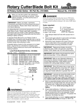
Serial Number Plate
For prompt service always use the serial number and
modelnumber when ordering partsfrom your Land Pride
dealer.Besuretoincludeyourserialandmodel numbers
incorrespondence also.Referto Figure1 forthe location
of your serial number plate.
Figure 1
Further Assistance
Your dealer wants you to be satisfied with your new
Rotary Cutter. If for any reason you do not understand
any part of this manual or are not satisfied with the
service received, the following actions are suggested:
1. Discuss the matter with your dealership service
manager making sure he is aware of any problems
you may have and that he has had the opportunity to
assist you.
2. If you are still not satisfied, seek out the owner or
general manager of the dealership, explain the
problem and request assistance.
3. For further assistance write to:
Land Pride Service Department
1525 East North Street
P.O. Box 5060
Salina, Ks. 67402-5060
E-mail address
lpser[email protected]
NOTE: A specialpoint of informationthat the operator
must be aware of before continuing.
21417
Land Pride welcomes you to the growing family of new
product owners.
ThisRotary Cutter hasbeendesigned with careand built
by skilled workers using quality materials. Proper
assembly, maintenance, and safe operating practices
willhelpyou getyearsof satisfactoryusefrom theRotary
Cutter.
Application
Land Pride’s RCR18 Series Rotary Cutters are built and
designed by Land Pride for cutting on gentle slopes or
slightly contoured right-of-ways, pastures, around the
farm or around town. The cutting widths, 60” for
RCR1860 and 72” for RCR1872, are compatible with the
more maneuverable 20 to 50 horsepower tractors with
540 rpm PTOspeed. The cutters have a category I three-
point hitch and are Quick Hitch adaptable. They are
offered with a standard ASAE Category 3 driveline with
either shear bolt or slip-clutch protection. Also, they are
offeredwitheitheralaminatedorasolidrubbertailwheel.
RCR18 Series Cutters cut through grass, weeds, and
light brush up to1 in. diameter. The RCR 1860 has a
cutting height range of 1-1/ 2” to 13” and the RCR1872
has a cutting height range of 1-1/2” to 11-1/2”. Cutting
blade tip speed for the RCR1860 is 16,363 fpm and for
the RCR1872 is 14,955 fpm. These units come with 10
ga. (.135” thick) x 24” diameter standard-duty stump
jumpers and welded on full length skid shoes. A metal
band shield is standard equipment for the rear. Optional
shields for the front and rear are rubber deflectors and
chainguards.See“Section 7:Features & Benefits” for
additional information.
Using This Manual
•
This Operator’s Manual is designed to help familiarize
you with safety, assembly, operation, adjustments,
troubleshooting, and maintenance. Read this manual
and follow the recommendations to help ensure safe
and efficient operation.
• The information contained within this manual was
current at the time of printing. Some parts may change
slightly to assure you of the best performance.
• To order a new Operator’s or Parts Manual contact
your authorized dealer. Manuals can also be
downloaded, free-of-charge from our website at
www.landpride.com or printed from the Land Pride
Service & Support Center by your dealer.
Terminology:
“Right” or “Left” as used in this manual is determined by
facing the direction the machine will operate while in use
unless otherwise stated.
Definitions:
IMPORTANT: A special point of information related
to its preceding topic. Land Pride’s intention is that
this information should be read and noted before
continuing.

8
Section 1: Assembly and Set-Up
RCR1860 and RCR1872 Series Rotary Cutters 312-849M
12/17/07
Land Pride
Table of Contents
Section 1: Assembly and Set-Up
Figure 1-1
21407
RCR1860 & RCR1872
Refer to Figure 1-1:
1. Loosen 5/8” locknuts (#5 & #13).
2. Remove 5/8” x 5” bolt (#9) and lay aside pivoting
upper hitch (#10) and hitch spacer (#11).
3. Rotate A-frame braces (#12) and rear frame
braces (#7) up to align with each other as shown.
Rear braces (#7) should be located outside of front
A-frame braces (#12).
4. Attachpivotingupper hitch (#10)and spacer (#11) to
A-frame braces (#12) with 5/8” x 5” bolt (#9). Secure
in place with locknut (#8).
5. Draw lock nuts (#5) up snug. Do not tighten. Tighten
all other 5/8” locknuts (#3, #8 & #13) to 170 ft.-lbs.
6. Install machine washer (#15) on pivot shaft of
tailwheel (#14).
7. Insert tailwheel pivot shaft (#14) into tailwheel
A-frame (#1).
8. Install second machine washer (#15) on pivot shaft
of tailwheel and secure with roll pin (#16).
9. Attach driveline hook (#17) to pivoting upper hitch
(#10) with 3/8” hex nut (#19). Tighten nut to the
correct torque.
10. Attach manual storage tube (#22) to the cutter deck
with two 1/4”-20 x GR5 hex head cap screws (#18).
1/4” lock washers (#21) and hex head nuts (#20).
Tighten nuts to the correct torque.
Tractor Requirements
The RCR18 Series Rotary Cutters are designed for use
with tractors that are equipped with a (540 RPM 1 3/8”-6
spline) rear power take-off (PTO).
The tractor must also provide for 3-point hitch
attachment Category I. The tractors rated drawbar PTO
horsepower on a 3-point should be no less than 20 HP
and no more than 50 HP.
Dealer Assembly
RCR1872 Tailwheel A-Frame
Refer to Figure 1-1:
1. The RCR1872 tailwheel A-Frame (#1) is shipped
with its short cross brace attached to the adjusting
bracket (#2). Remove 5/8” locknut (#3) and
5/8” x 1 1/2” bolt (#4).
2. Remove 5/8” locknuts (#5) and 5/8” x 2” bolts (#6)
from tailwheel A-frame.
3. Reinsert 5/8” x 2” bolts (#6) through deck tab, rear
brace (#7) and tailwheel A-frame (#1). Secure with
5/8”locknuts(#5). Drawnutsupsnug. Donottighten.
4. Reinsert 5/8” x 1 1/2” bolt (#4) and secure with
5/8” locknut (#3). Do not tighten.
NOTE: Ballast weights may be required to maintain
steering control. Refer to your tractor’s operator’s
manual to determine proper ballast requirements.
NOTE: Do not tighten hardware until assembly
is complete. Refer to “Torque Values Chart For
Common Bolt Sizes” on page 28.

9
Section 1: Assembly and Set-Up
12/17/07
RCR1860 and RCR1872 Series Rotary Cutters 312-849M
Land Pride
Table of Contents
Gearbox Vent Plug
Refer to Figure 1-2:
Remove gear box fill plug and replace with combination
vent/level plug shipped separate with Operator’s
Manual.
Figure 1-2
Tractor Hook-Up
Refer to Figure 1-3:
!
DANGER
Tractor hook-up to equipment is dangerous and can result in
serious injury or death. Do not allow anyone to stand between
Rotary Cutter and tractor during hook-up operations. Do not
operate hydraulic 3-point lift controls while someone is
directly behind tractor or near the cutter.
A 3-Point Category I hitch is required. The lower 3-Point
arms of the 3-Point hitch must be stabilized to prevent
side-to-side movement. Most tractors have sway blocks
or adjustable chains for this purpose.
20822
Oil Plug
DO NOT
OVERFILL
Vent Plug
1. Locate cutter on a flat level surface.
2. Slowly back tractor up to the Rotary Cutter while
using the tractor’s 3-point hydraulic control to align
lower 3-point arm holes with clevis lug holes on the
cutter.
3. Engage tractor park brake, shut tractor engine off
and remove key before dismounting from tractor.
4. With tractor’s lower hitch arms aligned and
positioned in the clevises, attach lower arms to the
clevises with hitch pins and secure with linch pins.
5. Connect top center 3-point link to upper pivot hitch
using customer supplied clevis pin and linch pin.
6. Ensure that the lower hitch arms are blocked to
prevent excessive side movement.
7. Return to the tractor and slowly raise and lower
implementcarefullyto ensure that the drawbar,tires,
and other equipment on the tractor do not contact
cutter frame. Move or remove drawbar if it interferes
with the cutter.
8. Manually adjust one of the two lower lift arms up or
down to level the Rotary Cutter from left to right.
9. Manually adjust the length of the top-link to level the
Rotary Cutter from front to rear. Final deck leveling
adjustments will be made later.
10. The arm lift rods on your tractor’s 3- point hitch
should be adjusted to allow for lateral float. Please
consult you tractor’s manual for adjusting
instructions.
Tractor Hook-Up
Figure 1-3
21422

10
Section 1: Assembly and Set-Up
RCR1860 and RCR1872 Series Rotary Cutters 312-849M
12/17/07
Land Pride
Table of Contents
Driveline Installation
If the Rotary Cutter is to be used on more than one
tractor, an additional driveline may be required
especially if a quick hitch is used.
!
CAUTION
Do not use a PTO adaptor. A PTO adapter will increase strain
on the tractor’s PTO shaft resulting in possible damage to the
shaft and driveline.
!
CAUTION
Tractor PTO shield and all Rotary Cutter guards must be in
place at all times during operation!
!
CAUTION
Always engage parking brake, shut off tractor and remove key
before dismounting from tractor.
!
WARNING
Damaged drivelines can cause serious injury or death.
Maximum PTO Driveline Movement During Operation
Figure 1-4
Driveline Minimum Length
IMPORTANT: The driveline must be lubricated
before putting it into service. Refer to “Lubrication”
on page 22.
IMPORTANT: Some tractors are equipped with
multispeed PTO ranges. Be certain your tractor ‘s
PTO is set for 540 rpm.
IMPORTANT: Avoid premature driveline
breakdown. A driveline that is operating must not
exceed an angle of 25 degrees up or down while
operating the 3-point lift. See Figure 1-4 below.
24872
IMPORTANT: Always check driveline minimum
length during initial setup, when connecting to a
different tractorand when alternating between using
aquickhitch and astandard 3-point hitch.Morethan
one driveline may be required to fit all applications.
Refer to Figure 1-6 on page 11:
1. Obtain the shortest distance possible between
tractor PTO shaft and gearbox shaft by starting the
tractor and slowly engaging 3-point lift to move the
lower arms up or down until the gearbox shaft is
aligned and level with the tractor's PTO shaft.
Securely block cutter deck in this position.
2. Place tractor gear selector in park, shut tractor
engine off, set park brake and remove switch key.
Refer to Refer to Figure 1-5:
3. Remove snap ring (#1) from the 3rd link pin shipping
location. Remove rubber protective sleeve from
gearbox input shaft and install driveline as follows:
SLIP-CLUTCH DRIVELINE:
a. Discard snap ring (#1).
b. Slide slip-clutch driveline (#5) onto the gearbox
input shaft.
c. Align holes in driveline with hole in gearbox shaft
andinsert1/2”x 31/2”long GR8bolt (#2).Secure
with 1/2” nut (#3) and 1/2” jam nut (#4).
d. Push and pull driveline to be sure it is securely
fastened to the gearbox shaft.
SHEAR-BOLT DRIVELINE:
a. Slide shear-bolt driveline onto gearbox shaft.
b. Install snap ring (#1) on gearbox shaft groove.
The snap ring is added security in the event the
shear-bolt should break.
c. Align holes in driveline with hole in gearbox input
shaft and insert 1/2” x 3 1/2” GR2 shearbolt (#2).
Secure with 1/2” nut (#3) and 1/2” jam nut (#4).
d. Push andpullthe drivelinetobe sureitis securely
fastened to the gearbox shaft.
Driveline Installation with Slip-Clutch Driveline Shown
Figure 1-5
NOTE: A driveline that is too long can damage
tractor, gearbox and/or driveline. Check driveline
withgearboxshaft alignedandlevelwith thetractor's
PTO shaft. This arrangement will provide the
shortest distance possible between the two shafts.
21408

11
Section 1: Assembly and Set-Up
RCR1860 and RCR1872 Series Rotary Cutters 312-849M
12/17/07
Land Pride
Table of Contents
4. Slide outer yoke of driveline over tractor's PTO shaft
and secure with locking collar.
5. If drivelinefits, skip to "DrivelineMaximumAllowable
Length". if driveline does not fit, continue with step 6
below.
6. The driveline will require shortening if it is too long to
fit between tractor and Rotary Cutter. Shorten
driveline as follows:
a. Check to makesure cutter and tractor PTOshafts
are level with each other and the deck is securely
supported at this height with support blocks.
b. Pull driveline profiles apart into two sections as
shown in Figure 1-6.
c. Attach outer driveline universal joint to tractor
PTO shaft and inner driveline universal joint to
gearboxshaft.Pull oneach drivelinesectiontobe
sure universal joints are secured.
d. Hold driveline sections parallel to each other to
determineiftheyaretoolong.Theinnerandouter
shieldsoneachsectionshouldendapproximately
1" short of reaching the universal joint shield on
the adjacent section (see “B” dimension). If they
are too long, measure 1" (“B” dimension) back
fromtheuniversaljointshield and make amark at
this location on the inner and outer shields.
e. Cut off inner shield at mark (“X” dimension). Cut
same amount off inner shaft (“X1” dimension).
Repeat cut off procedure (“Y”&“Y1” dimensions)
to cut outer driveline half.
f. Remove all burrs and cuttings.
Driveline Shortening
Figure 1-6
18347
Driveline Maximum Allowable Length
Be sure to check driveline minimum length before
checking driveline maximum allowable length.
Refer to Figure 1-7:
Driveline maximum allowable length, when fully
extended, must have a minimum overlap of profile tubes
by not less than 1/2 the free length with both inner and
outer profile tubes being of equal length.
Driveline Maximum Length
Figure 1-7
1. Measure and record driveline free length.
2. With the driveline profiles pulled apart, apply multi-
purpose grease to the inside of the outer profile and
reassemble the two profiles.
3. Move driveline halves together until profile tubes
overlap by 1/2 the free length. Measure and record
maximum allowable length shown in Figure 1-7.
4. Attach inner driveline yoke to gearbox shaft and
outer driveline yoke to tractor's PTO shaft.
5. Thedrivelineshould nowbe movedbackand forthto
insure thatboth ends are secured. Reattach any end
that is loose.
6. Hook a safety chain in the hole on the outer driveline
yoke shield and its opposite end to the tractor.
7. Hook the other safety chain in the hole on the inner
driveline yoke shield and its opposite end to the
cutter.
8. Start tractor and raise Rotary Cutter just enough to
remove support blocks from under the cutter deck.
9. Slowly engage tractor’s 3-point controls to lower
cutter. Check for sufficient drawbar clearance. Move
drawbar ahead, aside or remove if required.
10. Raise and lower implement to find the maximum
possible extended driveline length. Check to make
certain that the driveline has not extended beyond
the maximum allowable length recorded in step 3.
24804
Outer Shielding has been removed for clarity.
IMPORTANT: Two small chains are supplied with
the driveline. These chains must be attached to
outer and inner driveline yoke shields and to the
cutter and tractor to keep driveline shields from
rotating.

12
Section 2: Optional Equipment Set-Up
RCR1860 and RCR1872 Series Rotary Cutters 312-849M
12/17/07
Land Pride
Table of Contents
Front Guards
!
DANGER
Rotary Cutters have the ability to discharge objects at high
speeds. Use front and rear safety guards when cutting along
highways or in an area where people may be present.
Front Chain Guard Installation
Refer to Figure 2-1:
1. Install chain guards (#1, #2 & #3) as shown in Figure
2-1, with 3/8” x 1” long carriage bolts (#4), and 3/8”
flange nuts (#5).
2. Tighten all nuts to 31 ft-lbs as indicated in the
“Torque Values Chart For Common Bolt Sizes” on
page 28.
Front Rubber Guard Installation
Refer to Figure 2-2:
1. Install center rubber guard as shown with 3/8” x 1”
long carriage bolts (#1), flat strip (#5), rubber
deflector (#6) and 3/8” flange nuts (#2).
2. Install side rubber guards as shown with 3/8” x 1”
long carriage bolts (#1), flat strips (#3), rubber
deflectors (#4) and 3/8” flange nuts (#2).
3. Tighten all 3/8” flange nuts (#2) to 31 ft-lbs as
indicated in the “Torque Values Chart For Common
Bolt Sizes” on page 28.
Rear Guards
Rear Metal Guard Removal
Refer to Figure 2-3:
!
DANGER
Do not operator cutter without a rear guard. Do not remove
rear metal guard (#6) unless it is replaced by a Land Pride
chain guard or rubber guard. Serious body injury or loss of life
can result without a rear guard.
1. To remove rear metal guard, unscrew 3/8” flange
nuts (#1 & #2), remove flat washers (#3) and 3/8”
carriage bolts (#4 & #5).
2. Remove tailwheel adjusting bracket (#8) and rear
metalguard(#6). Reattach(#1, #3& #4)hardwareto
the metal guard for safe keeping. Store rear metal
guard for future use (i.e. when not using chain guard
or rubber guard).
3. Reattach tailwheel adjusting bracket (#8) with
3/8” x 1 1/2” carriage bolt (#5), flat bar (#7) and
3/8” flange nuts (#2).
4. Torque flange nuts (#2) to 31 ft-lbs.
Front Chain Guard
Figure 2-1
Front Rubber Guard
Figure 2-2
Standard Rear Metal Band
Figure 2-3
21400
21402
21418
Section 2: Optional Equipment Set-Up

13
Section 2: Optional Equipment Set-Up
12/17/07
RCR1860 and RCR1872 Series Rotary Cutters 312-849M
Land Pride
Table of Contents
Rear Chain Guard Installation
Refer to Figure 2-4:
1. Remove Rear Metal Guard. See “Rear Metal Guard
Removal” on page 12.
2. Install rear chain guard (#1) with 3/8” x 3 1/2” long
carriage bolts (#2), deflector spacer (#3) and
3/8” flange nuts (#4).
3. Tighten all nuts (#4) to 31 ft-lbs as indicated in the
“Torque Values Chart For Common Bolt Sizes” on
page 28.
Rear Rubber Guard installation
Refer to Refer to Figure 2-5:
1. Remove Rear Metal Guard. See “Rear Metal Guard
Removal” on page 12.
2. Install rear rubber guard (#1) with 3/8” x 3 1/2” long
carriage bolts (#2), deflector spacer (#3) and
3/8” flange nuts (#4).
3. Tighten all 3/8” flanged nuts (#4) to 31 ft-lbs as
indicated in the “Torque Values Chart For Common
Bolt Sizes” on page 28.
Rear Chain Guard
Figure 2-4
Rear Rubber Guard
Figure 2-5
21401
21403

14
Section 3: Adjustments
RCR1860 and RCR1872 Series Rotary Cutters 312-849M
12/17/07
Land Pride
Table of Contents
Section 3: Adjustments
Cutting Height
Figure 3-2
Cutting Height
21424
Blade Tip Blade Tip
This End Should Be Slightly
Higher Than Cutting Height
Deck Leveling & Height Adjustments
There are 4 primary adjustments that should be made
prior to actual field operation:
1. Deck Leveling From Left to Right
2. Deck Cutting Height
3. Center 3-Point Link Length
4. Tailwheel Height Adjustment
Proper adjustment of each of these items will provide for
higher efficiency, improved cutting performance and
longer blade life. The following tools will be needed:
• Pliable tape measure
• Spirit or carpenters level
• Open end or hex end wrench or socket set
• Protective gloves
!
DANGER
Engage parking brake, disengage PTO, shut off tractor and
remove key before proceeding. Ensure that all moving parts
have come to a complete stop before dismounting the tractor.
Deck Leveling From Left to Right
Refer to Figure 3-1:
1. Locate tractor with Rotary Cutter on a flat, level
surface.
2. Use tractor’s hydraulic 3-point control lever to lower
cutter until the tailwheel makes contact with the
ground surface.
3. Place a level or another suitable leveling device on
the front of the cutter deck as shown in Figure 3-1.
Manually adjust either one or both of the tractor’s
lower 3-point arm height adjustments to level the
deck from left to right. Some tractors have only a
single adjusting crank.
Deck Leveling
Figure 3-1
Deck Cutting Height
Refer to Figure 3-2:
!
CAUTION
Wearapair ofgloves whencheckingcutting height.Avoiddirect
contact with cutting edge of blade.
1. Using tractor’s 3-point hydraulic control, raise or
lower the 3-point arms until the front of the deck is
slightly lower than the rear of the deck.
2.
Thetopcenter linkshouldbe loosewhendeckrearis
supported by the tailwheel. If not, lengthen center
link until loose. Final adjustment will be made later.
3. With gloves on, carefully rotate each blade tip to the
position shown in Figure 3-2.
4. Measure distance from cutting tip of blade to ground
surface. This distance is the cutting height.
5. If desired cutting height cannot be obtained by
adjusting the lower 3-point arms, then readjust
tailwheel height as instructed on page 15.
6. Repeat steps 1 to 5 until desired cutting height is
achieved.
7. Set tractor’s 3-point hydraulic control stop at this
height.
21425
IMPORTANT: The blades should be positioned to
cut material only at the front of the cutter. If deck is
levelorbackof cutteris lowerthanthefront, thenthe
blades are subject to continuous material flow
resulting in additional blade wear, horsepower loss
and frequent blade sharpening.

15
Section 3: Adjustments
12/17/07
RCR1860 and RCR1872 Series Rotary Cutters 312-849M
Land Pride
Table of Contents
Center 3-Point Link Length
Refer to Figure 1-3 on page 9:
1.
Lower cutter deck to the nominal cutting height.
2. Adjust length of center 3-point link so that the upper
pivot hitch rest at a slight downhill position. This
arrangement allows for optimum ground contour
following performance.
3. Lockcenter link inthisposition once correct length is
achieved.
4. The second set of holes on the upper pivot hitch
should be used when tractor’s center 3-point link is
too short.
Tailwheel Height Adjustment
Refer to Figure 3-3:
If deck slope is slightly lower at the front than at the back
and cutting height is not at the desired height, then the
tailwheel must be adjusted up or down as follows:
1. Use tractor’s 3-point hydraulic control to lift cutter
until the tailwheel clears the ground.
2. Remove carriage bolt (#1) and 5/8” flange nut (#2).
3. Adjust tailwheel as follows:
• To lower cutting height, adjust tailwheel up.
• To increase cutting height, adjust tailwheel down.
4. With tailwheel adjusted tothecorrect height, replace
5/8” x 1 1/2” long carriage bolt (#1) and 5/8” flange
nut (#2). Tighten flange nut to the correct torque.
5. Readjust tractor’s lower 3-point arm height as
needed. See section titled “Deck Cutting Height” on
page 14.
Tailwheel Height Adjustment
Figure 3-3
21421

16
Section 4: Operating Instructions
RCR1860 and RCR1872 Series Rotary Cutters 312-849M
12/17/07
Land Pride
Table of Contents
Section 4: Operating Instructions
Operating Check List
Hazard control and accident prevention are dependent
upon the awareness, concern, prudence and proper
training involved in the operation, transport,
maintenance and storage of the Rotary Cutter.
Therefore, it is absolutely essential that no one operates
the Rotary Cutter without first having read, fully
understood and become totally familiar with the
Operator’s Manual. Make sure the operator has paid
particular attention to:
• Important Safety Information, pages 1 to 6
• Section 1: Assembly and Set-Up, page 8
• Section 3: Adjustments, page 14
• Section 4: Operating Instructions, page 16
• Section 5: Maintenance and Lubrication, page 19
The following inspection should be performed before
using the cutter.
Make the following inspections with cutter attached to a
tractor and PTO disengaged and completely stopped:
1. Inspect tractor safety equipment to make sure it is in
good working condition.
2. Carefully raise and lower implement to ensure that
thedrawbar,tires,andotherequipmentonthetractor
do not contact cutter frame or PTO driveline.
3. Check PTO guards to make certain they are in good
working condition and in place.
4. Disconnect main driveline from tractor PTO and
secure.
5. With cutter deck resting on solid supports, PTO
disengaged and completely stopped, check cutting
blades for sharpness.
6. Removesolidsupports fromunderthedeckandthen
verify cutter deck is set to the correct height. See
“Deck Leveling & Height Adjustments” on page 14.
The remaining inspections are made by engaging the
PTO to check for vibrations.
Operating Checklist
Check Referen
Read “Important Safety Information” Page 1
Read “Assembly & Set-up” Instructions. Page 8
Read “Operating Instructions” Page 16
Check cutter initially and periodically for
loose bolts & pins, See "Torque Values
Chart For Common Bolt Sizes".
Page 28
Make sure all guards and shields are in
place.
Page 1
Check oil level in gearbox. Page 22
Lubricate cutter and driveline as needed.
Refer to section on "Lubrication".
Page 22
7. Start tractor, set throttle to idle or slightly above idle
and slowly engage PTO. Initial start-up vibration is
normal and should stop after a few revolutions. Stop
PTO rotation immediately if vibration continues.
8. Once the cutter is running smoothly, increase tractor
PTO speed to 540 RPM. Stop PTO rotation
immediately if vibration occurs.
Transporting
!
CAUTION
When traveling on public roads, use accessory lights and
devices for adequate warning to operators of other vehicles.
Comply with all federal, state and local laws.
1. Makesure drivelinedoes not contacttractor orcutter
when raising cutter to transport position.
2. Reduce tractor ground speed when turning and
leave enough clearance so cutter does not contact
obstacles such as buildings, trees or fences.
3. Limit transport speed to 20 mph. Transport only with
a farm tractor of sufficient size and horse power.
4. Whentraveling onroadways,transportin such a way
that faster moving vehicles may pass you safely.
5. Shift tractor to a lower gear when traveling over
rough or hilly terrain.
Un-hooking the Rotary Cutter
Un-hook Rotary Cutter from the tractor as follows:
1. Park on a level solid surface.
2. Lowerdeckto groundlevelor onto blockssupporting
the deck just above ground level.
3. Engage tractor park brake, shut tractor engine off
and remove key before dismounting from tractor.
4. Disconnect driveline from tractor PTO shaft.
5. Un-hook 3-point hitch from tractor. Reinstall hitch
pins, linch pins and hair pin cotters in cutter hitch.
6. Rotate driveline storage hook down and place
driveline in storage hook.
7. See “Cutter Storage” on page 21 if cutter is to be
stored for a long time.
IMPORTANT: Stop PTO immediately if vibration
continues after a few revolutions during start-up and
anytimeit occurs thereafter. Wait forPTO to come to
a complete stop before dismounting from tractor to
check for probable causes. Make necessary repairs
and adjustments before continuing on.
IMPORTANT: Do not exceed rated cutter PTO
speed. Excessive engine speed will cause damage
to the power train components.
IMPORTANT: Always disengage the tractor’s PTO
before raising the cutter to transport position.

17
Section 4: Operating Instructions
12/17/07
RCR1860 and RCR1872 Series Rotary Cutters 312-849M
Land Pride
Table of Contents
Cutting Instructions
!
CAUTION
Do not over speed PTO or machine damage may result. This
cutter is designed to be used only with a tractor having a 540
RPM rear PTO.
!
WARNING
The RCR18 series cutter is designed to cut grass and brush up
to 1” in diameter. Using this cutter for another type of work
can damage drive components, deck and support frame.
!
DANGER
Gearbox and driveline shields must be secured in place when
operating to avoid injury or death from entanglement in
rotating drivelines.
!
DANGER
Rotary Cutters have the ability to discharge objects at high
speeds. Therefore, the use of front & rear deck safety shields
is strongly recommended when cutting along highways or in
an area where people may be present!
!
DANGER
Never operate the cutter in the raised position. The cutter can
discharge object at high speeds resulting in injury or death.
!
DANGER
Do not cut on steep inclines. The tractor and cutter could flip
over causing damage to the equipment, bodily injury or death.
!
DANGER
Do not use cutter to lift or carry objects. Lifting and/or
carrying objects can result in damage to the cutter, serious
bodily injury or death.
!
DANGER
Never carry a person on the cutter. A person can fall and be
ran over by the cutter or tractor causing serious injury or
death.
!
DANGER
Do not use deck as a working platform. The deck is not
properly designed or guarded for this use. Using deck as a
working platform can cause serious injury or death.
!
DANGER
Do not use deck as a fan. Cutting blades are not properly
designed or guarded for this use. Using the deck as a fan can
result in injury or death.
This cutter was designed to cut grass and brush in right-
of-ways, pastures and for shredding row crop residues.
Cutting should not be done in dry conditions. Wet
material will build up on the deck underside creating
additional horsepower, high wear, and poor discharge.
1. Thoroughly inspect the area to be cut for debris and
unforeseen objects. Mark any potential hazards.
2. Start the machine slowly; do not use full throttle.
Allow 10 seconds for cutter blades to become
aligned properly before going to 540 RPM.
3. Travelonly as fastas the tractoris capableof making
smooth even cuts without overloading the tractor.
Ground speed depends upon two things:
• The density of the material being cut.
• The size of tractor operating the cutter.
4. After the first 50 feet, stop and check to see that the
cutter is adjusted properly.
5. Do not engage PTO when cutter is in the fully raised
or lowered positions.
6. Periodically disengage PTO, turn off tractor, remove
ignition key and check for foreign objects wrapped
around the rotor shaft. Block cutter deck up before
removing objects.
7. Frequently inspectthecutterforlooseboltsandnuts.
Tighten all loose bolts and nuts as indicated in the
“Torque Values Chart For Common Bolt Sizes” on
page 28.
General Operating Instructions
It is important that you familiarized yourself with the
Operator’s Manual, completed Operators Checklist,
properly attached cutter to your tractor, made leveling
adjustments, and preset your cutting height before
beginning a running operational safety check on your
Land Pride Rotary Cutter.
The running operational safety check may now be done.
It is important that at any time during this safety check
youdetectamalfunction ineitherthecutter ortractorthat
you immediately shut the tractor off, remove its’ key, and
make necessary repairs and/or adjustments before
continuing on.
Make sure before starting the tractor that the park brake
is engaged, the PTO is disengaged, and the cutter is
restingontheground.Startthetractor andsettheengine
throttle speed at a low idle. Raise the cutter with the
NOTE: Your Rotary Cutter is equipped with free
swinging cutting blades to reduce shock loads when
striking obstacles. However, it is best to avoid
striking obstacles to extend cutter life and life of
cutting blades.
IMPORTANT: It is important to maintain correct PTO
speed. Loss of PTO speed will allow blades to hinge
back and result in ragged, uneven cutting.

18
Section 4: Operating Instructions
12/17/07
RCR1860 and RCR1872 Series Rotary Cutters 312-849M
Land Pride
Table of Contents
tractor’s rear hydraulic lift control lever to transport
position making sure that the PTO shaft does not bind
anddoesnotcontactthecutter frame.Lowerthecutterto
the ground and at a low engine speed engage the PTO.
If everything is running smoothly at a low idle, slowly
raise the cutter to transport height checking for bind or
chatter in the driveline. Lower the cutter to the ground
and increase the tractor’s engine rpm until it reaches the
cutter full PTO operating speed of 540 rpm. If everything
is still running smoothly, once more raise the cutter to
transport height to check for driveline bind or chatter.
Lower the cutter to the ground, return the engine to a low
idle, and disengage the PTO. Position the adjustable
stops on the tractor’s hydraulic lift lever so the cutter can
be consistently returned to the same cutting and
transport height.
You should now be ready to transport to your cutting site
at a safe ground speed. On roadways transport in such a
manner that faster moving vehicles can easily see you
and pass you safely. Reduce your speed when travelling
overroughandhillyterrain. Avoidquickorsharpsteering
corrections. Take extra care to insure that the mower
doesn’t come into contact with obstacles such as trees,
buildings or fences. Use accessory lights and
appropriate reflective devices to provide adequate
warningtopedestriansand othervehicleoperatorswhen
travelingon public roads andin the dark ofnight. Comply
with all local, state and federal laws.
It is important that you inspect the area where you will be
cutting and clear it of safety hazards and foreign objects
either before or after you arrive at the cutting site. Never
assume the area is clear. Cut only in areas you are
familiar with and are free of debris and unseen objects.
Extremely tall grass should be cut twice to detect
potential hazards. In the event you do strike an object
stop the cutter and tractor immediately to inspect and
make necessary repairs to the cutter before resuming
operation. It really pays to inspect a new area and to
develop a safe plan before cutting.
You will need to maintain 540 rpm PTO speed and 2 to 5
mphgroundspeedto produceaclean cut.Makeatractor
gear and range selection that will enable you to maintain
these speed combinations. Generally the quality of cut is
better at lower ground speeds. Dense ground cover will
create the need to slow down even more. In certain
conditions tractor tires will roll grass down resulting in an
uneven cut when the grass fails to rebound. Should this
happensyou maytryreversing thedirection ofcut and/or
double cut to achieve the desired finish. Avoid very low
cutting heights especially on extremely uneven terrain.
Always cut downward on slopes and avoid crossing the
face of steep slopes. Avoid sharp drops and cross
diagonally through dips to prevent hanging up the tractor
and cutter. Slow down in turns. Remember to look back
often.
Nowthatyou’re preparedandwell briefedyoumay begin
cutting. Begin mowing by doing the following:
• Reducing the tractor’s engine rpm
• Make sure thecutter is onthe ground incutting position
• Engage the PTO
• Raise the engine rpm to the appropriate PTO speed
• Begin mowing.
Make wide turns when possible. Three-point hitch and
optional Quick-Hitch models can be lifted into transport
position to make tight turns and to reverse direction. Try
increasing or decreasing ground speed to determine the
effect on quality of cut. With a little practice you will be
pleasedwithwhatyouandyourLand PrideRotaryCutter
can do.
Whether you are done mowing, need to take a break, or
just need to make a few adjustments to the cutter,
remember to always do the following:
• Reduce the tractor’s engine rpm
• Disengage the PTO
• Stop on level ground
• Set the park brake
• Turn off the engine and remove the key
• Stay on the tractor until the cutter blades have come to
a complete dead stop.
Page is loading ...
Page is loading ...
Page is loading ...
Page is loading ...
Page is loading ...
Page is loading ...
Page is loading ...
Page is loading ...
Page is loading ...
Page is loading ...
Page is loading ...
Page is loading ...
/