Page is loading ...

AIR GREASE GUN
Model 00219
ASSEMBLY and OPERATING INSTRUCTIONS
Diagrams within this manual may not be drawn proportionally.
Due to continuing improvements, actual product may differ slightly from the product described herein.
Distributed exclusively by Harbor Freight Tools
®
.
3491 Mission Oaks Blvd., Camarillo, CA 93011
Visit our website at: http://www.harborfreight.com
Read this material before using this product.
Failure to do so can result in serious injury.
SAVE THIS MANUAL.
Copyright
©
2004 by Harbor Freight Tools
®
. All rights reserved. No portion of this manual
or any artwork contained herein may be reproduced in any shape or form without the
express written consent of Harbor Freight Tools.
For technical questions or replacement parts, please call 1-800-444-3353.
REV 11h

For technical questions, please call 1-800-444-3353.
Page 2SKU 00219
Specifications
Save This Manual
You will need the manual for the safety warnings and precautions, assembly instructions,
operating and maintenance procedures, parts list and diagram. Keep your invoice with this
manual. Write the invoice number on the inside of the front cover. Keep the manual and in-
voice in a safe and dry place for future reference.
Safety Warnings and Precautions
WARNING: When using tool, basic safety precautions should always be followed to
reduce the risk of personal injury and damage to equipment.
Read all instructions before using this tool!
1. Keep work area clean. Cluttered areas invite injuries.
2. Observe work area conditions. Do not use machines or power tools in damp or wet
locations. Don’t expose to rain. Keep work area well lit.
3. Keep children away. Children must never be allowed in the work area. Do not let them
handle machines, tools, extension cords, or air hoses.
4. Store idle equipment. When not in use, tools must be stored in a dry location to inhibit
rust. Always lock up the Air Grease Gun and the grease, in a location that is out of reach
of children.
5. Use the right tool for the job. Do not attempt to force a small tool or attachment to
do the work of a larger industrial tool. There are certain applications for which this
tool was designed. It will do the job better and more safely at the rate for which it was
intended. Do not modify this tool and do not use this tool for a purpose for which it was
not intended.
6. Dress properly. Do not wear loose clothing or jewelry as they can be caught in
moving parts. Protective, electrically non-conductive clothes and non-skid footwear are
recommended when working. Wear restrictive hair covering to contain long hair.
Air Inlet 1/4” - 18 NPT Female
Maximum Air Pressure 100 PSI
Capacity 400 cc Bulk, 14 oz. Canister
Flex Hose Length 9” L
Air Consumption 4 CFM @ 90 PSI
Recommended Hose Size 3/8”
Stiff Nozzle Length 6”
Canister Dimensions 10-7/8” x 2-1/4” Dia.
Air Inlet Screen 20 Mesh
Spout Tip Dimensions 1-1/2” L x 9/16” Dia.
REV 05g

For technical questions, please call 1-800-444-3353.
Page 3SKU 00219
7. Use eye and ear protection. Always wear ANSI approved impact safety goggles. Wear
an ANSI approved dust mask or respirator when working around chemical dusts and
mists.
8. Do not overreach. Keep proper footing and balance at all times. Do not reach over or
across running machines or air hoses.
9. Maintain tools with care. Keep tools clean for better and safer performance. Follow
instructions for lubricating and changing accessories. Inspect tool cords and air hoses
periodically and, if damaged, have them repaired by an authorized technician. The handles
must be kept clean, dry, and free from oil and grease at all times.
10. Disconnect air supply. Disconnect air hose and turn off the compressor when not in
use.
11. Remove adjusting keys and wrenches. Check that keys and adjusting wrenches are
removed from the tool or machine work surface before plugging it in.
12. Avoid unintentional starting. Do not carry any tool with your finger on the trigger,
whether it is connected to the air compressor or not.
13. Stay alert. Watch what you are doing, use common sense. Do not operate any tool when
you are tired.
14. Check for damaged parts. Before using any tool, any part that appears damaged
should be carefully checked to determine that it will operate properly and perform its
intended function. Check for alignment and binding of moving parts; any broken parts
or mounting fixtures; and any other condition that may affect proper operation. Any part
that is damaged should be properly repaired or replaced by a qualified technician. Do
not use the tool if any switch does not turn On and Off properly.
15. Guard against electric shock. Prevent body contact with grounded surfaces such as
pipes, radiators, ranges, and refrigerator enclosures.
16. Replacement parts and accessories. This product is to be repaired and serviced only
by a qualified technician. When this product is serviced, only identical replacement parts
should be used. Use of any other parts will void the warranty. Only use accessories
intended for use with this tool. Approved accessories are available from Harbor Freight
Tools.
17. Do not operate tool if under the influence of alcohol or drugs. Read warning labels
if taking prescription medicine to determine if your judgement or reflexes are impaired
while taking drugs. If there is any doubt, do not operate the Grease Gun.
18. Use proper size and type extension cord. If an extension cord is required, it must be
of the proper size and type to supply the correct current to the air compressor without
heating up. Otherwise, the extension cord could melt and catch fire, or cause electrical
damage to the tool. Check your air compressor’s manual for the appropriate size cord.
19. Maintenance. The maintenance outlined in the maintenance section should be performed
regularly. For your safety, this product should be serviced or repaired regularly only by
a qualified technician.
20. Compressed air only. Never use combustible gas as a power source.

For technical questions, please call 1-800-444-3353.
Page 4SKU 00219
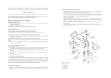
Operation
For best service you should incorporate an oiler, regulator, and inline filter, as shown in
the diagram above. Hoses, couplers, oilers, regulators, and filters are all available at Harbor
Freight Tools.
1. If desired, for quick tool connection, you will need to prepare a 1/4” quick air connector
(not included) to connect to the air source hose. First, wrap the 1/4” quick air connec-
tor (not included) with pipe thread seal tape (not included) before threading it onto the
3/8” air source hose. Then, connect the 1/4” quick air connector to the Air Inlet (2) on
the Grease Gun.
Note: If you are not using an automatic oiler system, before operation, add a few drops
of Pneumatic Tool Oil to the airline connection. Add a few drops more after each hour
of continual use.
2. To check your air system, set the air pressure on your compressor to 90 PSI. Do not
exceed the testing air pressure of 90 PSI.
3. Check the air connection for leaks. After test is complete, disconnect from the air supply
until grease is loaded into the Air Grease Gun.
Unpacking
When unpacking, check to make sure the parts listed on page 9 are included. If any
parts are missing or broken, please call Harbor Freight Tools at the number on the cover of
this manual as soon as possible.
21. Check hoses carefully. Never use the Grease Gun if the hoses are cracked, frayed, or
kinked. Avoid problems by not severely bending the hoses. If hoses appear damaged,
have them replaced.
22. This Grease Gun is designed only to hold and dispense grease. Never use it to hold
and dispense any other material.
Note: Performance of the compressor (if powered by line voltage) may vary depending
on variations in local line voltage. Extension cord usage may also affect tool
performance.
Warning: The warnings, cautions, and instructions discussed in this instruction manual
cannot cover all possible conditions and situations that may occur. It must be understood
by the operator that common sense and caution are factors which cannot be built into
this product, but must be supplied by the operator.
Grease
Gun
1/4”-18 NPT Female

For technical questions, please call 1-800-444-3353.
Page 5SKU 00219
Front Housing (7)
Trigger (3)
Air Inlet (2)
Joint (8)
Flexible Hose Assy.
(9b)
Rigid Coupler Assy. (9)
Tube (18)
Follower Rod (19)
FIGURE A
FIGURE B
FIGURE C
Locking Plate (20)
Handle (21)
Air Vent
(11)
Fill
Nozzle
(10)
Top of Tube (18)
on the Head (7)
Rear Housing (1)
Handle
(21)
REV 05g

For technical questions, please call 1-800-444-3353.
Page 6SKU 00219
Grease Loading Instructions
Warning!! Make sure the Grease Gun is not attached to the air source hose when
loading grease.
Grease can be loaded into the Grease Gun by loading with a filler pump (FIGURE 1), using
suction filling (FIGURE 2), or loading with a cartridge (FIGURE 3).
Loading a grease cartridge (not included).
See the Assembly Drawing on page 10, Figures A, B, and C on page 5 and
FIGURE 3 below.
1. Remove the Tube (18) from the top of the Front Housing (7).
2. Pull back on the Handle (21) until it is fully extended. Lock it into place with the Locking
Plate (20).
3. Remove the caps/lids from both ends of the cartridge (not included). Insert the cartridge
into the Tube (18) in the orientation indicated on the cartridge, making sure that it is in
as far as possible.
4. Reassemble the Tube (18) to the top on the Front Housing (7). Press the Locking Plate
(20) and release the Handle (21). Press the Handle (21) in as far as it will go.
Suction Filling (FIGURE 2)
See the Assembly Drawing on page 10, Figures A, B, and C on page 5 and
FIGURE 2 above.
1. Remove the Tube (18) from the top of the Front Housing (7).
2 Submerge the open end of the Tube (18) approximately 2 inches into the grease
container (not included).
3. Slowly, pull back and fully extend the Handle (21) to draw grease upward into
the Tube (18). When the Handle (21) is fully extended, lock it into place with the
Locking Plate (20).
4. Carefully, reassemble the Tube (18) to the top on the Head (7). Press the Locking
Plate (20) and release the Handle (21). Press the Handle (21) in as far as it will go.
FIGURE 1 FIGURE 2
FIGURE 3
Suction Filling Cartridge Filling
Filler Pump Filling
Filler Hose with
Plug on the Pump
(not included)
enters the
Nozzle (10)
Cartridge
Tube (18)
Nozzle
(10)
REV 05g

For technical questions, please call 1-800-444-3353.
Page 7SKU 00219
Loading with a Filler Pump (not included)
See the Assembly Drawing on page 10, Figures A, B, and C on page 5 and
FIGURE 1 on page 6.
1. Slowly, pull back and fully extend the Handle (21). Lock it into place with the
Locking Plate (20).
2. Insert the Filler Plug on the end of the hose of the Filler Pump (not included) into the
Nozzle (10).
3. Follow the instructions provided in the Filler Pump manual (not included) to operate
the Filler Pump until the Tube (18) is full.
4. Disconnect the Grease Gun from the Filler Pump (not included).
5. Press the Locking Plate (20) and release the Handle (21). Press the Handle (21) in
as far as it will go.
Operating the Grease Gun
Note: If your application requires the Flexible Hose (9b), attach it to the Rigid
Coupler (9).
Note: If your Grease Gun fails to work, it is usually because air pockets have formed
in the Gun. To remove them, disconnect the Grease gun from the air supply. Pull back
and fully extend the Handle (21). Now push the Handle forward into the Grease Tube
while depressing the Air Vent Valve (11). Reconnect the air supply to the Grease gun
and then squeeze and release the Trigger (3) several times until the trapped air is ex-
pelled. Repeat as needed.
See FIGURE C on page 5.
Before every use, prime the Grease Gun by operating the Gun (see below) until
grease flows from the tip. If it does not prime properly, follow the directions
above for venting trapped air.
1. Attach the Grease Gun to the air source hose following the directions on page four.
Set the air compressor to 30 - 100 PSI.
2. Squeeze the Trigger (3) to inject a small amount of grease. Release and squeeze the
trigger repeatedly to inject more grease.
3. Disconnect from the air source hose before refilling the Grease Gun. Turn off the air
compressor.
Warning!! The Grease Gun may still have air pressure after disconnected from the
air source. Point the Grease Gun into a suitable receptacle and fire it until all of the
air is expended.
REV 05I; 06g

For technical questions, please call 1-800-444-3353.
Page 8SKU 00219
Troubleshooting
If the Grease Gun does not operate:
1. Check that gun is properly connected to the air source and the air compressor is set
to 30 - 100 PSI.
2. If it still doesn’t operate, take it to an qualified service technician to check the Springs
(6 and 17), and the Piston Assembly (5).
If the Grease Gun cycles and does not pump grease:
1. Repeat priming operation on page 7.
2. Check to see if you are out of grease.
3. Disconnect any extensions and prime until grease flows.
If the Grease Gun continues to lose prime:
1. Release trapped air.
2. Refill the Grease Gun and repeat priming.
3. Have an qualified service technician check the position on the Follower Assembly.
If the Grease Gun still doesn’t operate, contact a qualified service technician.
Maintenance
Always disconnect from the air source hose before attempting any maintenance.
1. After each use, clean leftover grease from the Tube (18).
2. Make sure the Nozzle (10) and the tip of the Grease Gun are clear of dirt, grease, or
any debris.
3. Wipe down the unit with a lint free cloth.
REV 09b

For technical questions, please call 1-800-444-3353.
Page 9SKU 00219
NOTE: Some parts are listed and shown for illustration purposes only and are not available individually as re-
placement parts.
PLEASE READ THE FOLLOWING CAREFULLY
THE MANUFACTURER AND/OR DISTRIBUTOR HAS PROVIDED THE PARTS DIAGRAM IN THIS
MANUAL AS A REFERENCE TOOL ONLY. NEITHER THE MANUFACTURER NOR DISTRIBU-
TOR MAKES ANY REPRESENTATION OR WARRANTY OF ANY KIND TO THE BUYER THAT
HE OR SHE IS QUALIFIED TO MAKE ANY REPAIRS TO THE PRODUCT OR THAT HE OR SHE
IS QUALIFIED TO REPLACE ANY PARTS OF THE PRODUCT. IN FACT, THE MANUFACTURER
AND/OR DISTRIBUTOR EXPRESSLY STATES THAT ALL REPAIRS AND PARTS REPLACEMENTS
SHOULD BE UNDERTAKEN BY CERTIFIED AND LICENSED TECHNICIANS AND NOT BY THE
BUYER. THE BUYER ASSUMES ALL RISK AND LIABILITY ARISING OUT OF HIS OR HER
REPAIRS TO THE ORIGINAL PRODUCT OR REPLACEMENT PARTS THERETO, OR ARISING
OUT OF HIS OR HER INSTALLATION OF REPLACEMENT PARTS THERETO.
Parts List
Part Description Q’ty
1 Rear Housing 1
2 Air Inlet 1
3 Trigger Assembly 1
4 Pan HD Screw 4
5 Piston Assembly 1
6 Spring 1
7 Front Housing 1
8 Joint 1
9 Rigid Coupler Assembly 1
9b Flexible Hose Assembly 1
10 Fill Nozzle 1
11 Air Vent Valve 1
12 Gasket 1
13 Lock Nut 1
14 Plunger 1
15 O-Ring 1
16 Backlash Gasket 1
17 Large Spring 1
18 Tube 1
19 Follower Rod 1
20 Locking Plate 1
21 Handle 1
REV 05g; 06g

For technical questions, please call 1-800-444-3353.
Page 10SKU 00219
Assembly Drawing
REV 05g

For technical questions, please call 1-800-444-3353.
Page 11SKU 00219
90 DAY WARRANTY
Harbor Freight Tools Co. makes every effort to assure that its products meet high quality and
durability standards, and warrants to the original purchaser that this product is free from de-
fects in materials and workmanship for the period of 90 days from the date of purchase. This
warranty does not apply to damage due directly or indirectly, to misuse, abuse, negligence or
accidents, repairs or alterations outside our facilities, criminal activity, improper installation,
normal wear and tear, or to lack of maintenance. We shall in no event be liable for death, in-
juries to persons or property, or for incidental, contingent, special or consequential damages
arising from the use of our product. Some states do not allow the exclusion or limitation of
incidental or consequential damages, so the above limitation of exclusion may not apply to
you. This warranty is expressly in lieu of all other warranties, express or implied, including the
warranties of merchantability and tness.
To take advantage of this warranty, the product or part must be returned to us with trans-
portation charges prepaid. Proof of purchase date and an explanation of the complaint must
accompany the merchandise. If our inspection veries the defect, we will either repair or
replace the product at our election or we may elect to refund the purchase price if we cannot
readily and quickly provide you with a replacement. We will return repaired products at our
expense, but if we determine there is no defect, or that the defect resulted from causes not
within the scope of our warranty, then you must bear the cost of returning the product.
This warranty gives you specic legal rights and you may also have other rights which vary
from state to state.
3491 Mission Oaks Blvd. • PO Box 6009 • Camarillo, CA 93011 • (800) 444-3353
REV 11h
/