Page is loading ...

12
SM-135
SPECIFICATIONS
PROBLEM CAUSE & SOLUTION
Tool becomes sluggish
Dirt or oil gum accumulation on internal parts
—Flush with kerosene, operate for 30 seconds and re-
lubricate.
Loss of Power
1. Worn Blades
—Replace the Blades.
2. Worn Rotor, Cylinder, or accessory
—Replace worn parts.
Model no. TP-302
Tube ID Range
5/8” to 2-1/4”
RPM
6500
Dimensions
5” X 12” X 13”
Weight (LBS)
16
Air Pressure (PSI)
90
Air Inlet
1” NPT
Operating Hose
1”
Air Flow
130 CFM
Scavenger Inlet
3/8” NPT
Spindle
1-1/16 X 12 THREAD
Thomas C. Wilson, Inc.
21-11 44th Avenue, Long Island City, New York 11101
Tel: (718)729-3360 Fax: (718)361-2872 http://www.tcwilson.com
E-mail: [email protected]
TROUBLE-SHOOTING
SM-135
Thomas C. Wilson, Inc.
21-11 44th Avenue, Long Island City, New York 11101
Tel: (718)729-3360 Fax: (718)361-2872 http://www.tcwilson.com
E-mail: [email protected]
TO REDUCE THE RISK OF INJURY AND EQUIPMENT DAMAGE
USER MUST READ AND UNDERSTAND OPERATOR’S MANUAL.
Rev: A, 5/11/2007
OPERATING INSTRUCTIONS
&
SERVICE MANUAL
AIR DRIVEN TUBE CLEANER
MODEL TP-302

2
SM-135
SAFETY INSTRUCTIONS
1. Do not allow corrosive gases or foreign material to enter the unit. Moisture, oil-
based contaminants, or other liquids must be filtered out.
2. Eye protection is always required when running motor.
3. Hearing protection is recommended when in close proximity to all operating air
motors.
4. Dust mask, non-skid safety shoes, hard hat, gloves and other personal safety equip-
ment must be used.
5. Stay alert, watch what you are doing, and use common sense when operating a
power tool.
6. Dress properly. Do not wear loose clothing or jewelry.
7. Keep your work area clean and well lit.
8. Do not operate power tools in explosive atmospheres, such as in the presence of
flammable liquids, gases, or dust.
9. Disconnect the tool from the air supply before installing, making any adjustment,
changing accessories, servicing or storing tool.
READ AND UNDERSTAND ALL INSTRUCTIONS
Failure to follow all instructions listed below, may result
in accident, fire and/or personal injury.
SAVE THESE INSTRUCTIONS
WAR NING!
!
11
SM-135
AIR THROTTLE - DISASSEMBLY
To remove, turn grip lock, key 24, to unlocked position and unscrew
live handle assembly, key 32, taking care not to lose the small cam
follower rolls, key 29, when pulling the handle from the body. The
entire throttle assembly comes out, permitting cleaning.
Further disassembly will require pushing out the pin, key 28, which
passes through the cam follower rolls, key 29, in the helical slots
of the handle grip, key 30. This releases the valve and stem, key
27. Compressing the valve spring, key 26, slightly will facilitate
this. (Be careful not to lose the small rolls.)
The valve stem seal in live handle assembly, key 32, is press-fitted
into its bushing - within. It may be pulled out with a hooked in-
strument. The replacement seal should be pressed into place with
its sealing member facing in the same direction as that of the pre-
vious seal. It is recommended, however, that instead of performing
those operations, a right handle sub-assembly, Catalog #7598 be pur-
chased which includes the handle, plug, bushing, and seal.
The handle grip spring, key 31, is compressed into the handle grip,
key 30, forcing the end of the spring into hole in the grip. The
grip is then slipped onto the handle so that the other spring end
enters the hole in the band of the handle. The valve spring, key
26, is placed over the stem of the assembled valve, key 27, and
the stem carefully inserted through the valve seal. (Oil on the
stem will facilitate this.) With the handle grip rotated clock-
wise (viewed from the valve end) as far as the spring will permit,
the cam follower pin, key 28, is passed through the helical cain
slots in the grip and with the valve spring compressed, through the
hole in the valve stem. The assembly is completed by placing the
cam follower rolls, key 29, on the pin. In order to do this, it is
necessary to have the valve spring compressed.
Before the right handle assembly, Catalog #7598 is screwed home in
the body, key 2, the handle grip bearing, key 25, should be placed
at the bottom of the bore for the grip. This bearing should be
replaced if it wears thinner than 1/32". It is desirable to use
some anti-seize lubricant (such as Parker Appliance Company
"Thread-Lube") on the handle threads.
AIR THROTTLE - ASSEMBLY

10
SM-135
GENERAL IMPORTANT NOTES
Worn parts should be replaced as required.
Synthetic rubber "0" ring seals may be pried out of their
grooves in the rear journal and the rear plug and replaced.
Replacement of the Front Bushing, in housing, involves
pushing the old bushing inward from the front end of the
body and forcing a new bushing into place from the inside
of the body.
The rear bushing may be pushed out of the rear journal in
either direction, preferably rearward. To replace, observe
that longitudinal pin is in place, align the groove in the
bushing with the pin and press into place from the rear until
the front of bushing and front face of the journal is flush.
Great Care should be taken to avoid damage or distortion to
the 3/8" diameter scavenger tube, force-fitted into the end
of rotor. This tube must run concentric with the rotor, other-
wise leaks may develop.
The motor should be run a short time at low speed, after assem-
bly, without any scavenging flow to fully seat the sealing sur-
faces. Do not run at free (no load) speeds over extended per-
iods. Be sure to introduce lubricating oil into the operating
air line whenever the TP-302 is in operation.
Keep the oil-impregnated front bushing and thrust ball bearing
supplied with oil by filling the reservoir through the oil hole
in the nose of the body. Remove Set Screw, key 3.
3
SM-135
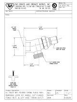
RECOMMENDED OPERATING AIR PRESSURE 90 PSI
OPERATION
AIR INLET
1” NPT
SPINDLE
1-1/16 X 12 THREAD
ROLL THROTTLE
VALVE
PROPER PIPING FOR AIR TOOLS
SCAVENGER INLET
3/8 NPT
DEAD
HANDLE

4
SM-135
Caution: Disassembly or reassembly of the unit must be performed by qualified personnel.
It is advisable to return units to the factory or consult the factory for necessary repair.
PARTS LIST
9
SM-135
6. Place "0" Ring Seals, key 10, in outside grooves of Rear Journal and Bushing As-
sembly, key 9. Place rear journal and bushing within, over rear shaft of rotor, with
locating pin downward, aligning pin of rear journal with pin hole in cylinder. Rear
journal will have to be lightly pressed or tapped on as the "0" ring seals start bear-
ing against body. Lubricate "0" ring seals to make them slide easier.
CAUTION: Be sure locating pin enters pin hole in cylinder and not in cylinder
notch. To further assist proper location, note the two "assist" holes 1800 apart on
back of rear journal. One of these "assist" holes is in direct line with the locating pin
at front end of rear journal. Make a mark at the very end of the motor body in line
with correct location of the pin. Aligning the proper "assist" hole with this groove
will assure accurate journal location and seating. The only resistance to a "slip fit
assembly" is the pressure of the two "0" rings against body wall. A slight lifting of
the rotor may facilitate assembly at this point. When rear journal is properly located
and seated, the rotor will have approximately .005" end play, barely detected by ac-
tual feel. If misalignment does occur, the rear journal should be lifted slightly and
then rotated by using a spanner wrench or the insertion of a push pin in the"assist"
hole.
7. Place key 11, Seat Gasket, in the counterbored end of the rear journal.
8. Place key 12, Seal Seat, on gasket with the 3/4" diameter projecting hub facing
upward. (This hub is part of the actual rotary seal and is lapped to a fine surface--Do
not cause any scratches.)
9. Sub-assemble, if not already assembled, scavenger seal (small "0" ring) on inside
of carbon-type Seal Ring, key 13.
10. Place Seal Ring with 3/4" diameter projecting hub downward, on to threaded
end of scavenger tube in rotor end. (The face of the projecting hub, is the actual ro-
tary seal and is lapped to a fine surface--Do not cause any scratches.) Screw into
place counter-clockwise (do not press down over threads) until it meets hub of Seal
Seat, key 12. Lubricate slightly at this
meeting position.
11. Place Washer, key 14, in position.
12. Place Spring, key 15, in position.
13. Place Seal Ring Fork, key 16, in position and screw home in a counter-
clockwise direction.
14. Cap and lock final assembly in place with Rear Plug, key 17. Be sure "0" Ring,
key 18, is also in place. The motor is now ready for use or properly prepared for
storage.

8
SM-135
1. Check for burrs on rotor wrench flats and remove any with a file. (Flats are apt to
burr through wrench slippage.)
2. Place dead handle of motor in a horizontal position in a vise and secure.
3. Unscrew, counter-clockwise, key 17, Rear Plug.
4. Unscrew, clockwise, (left hand thread) key 16, Seal Ring Fork.
5. Remove key 15, Seal Spring.
6. Remove key 14, Spring Washer.
7. Remove key 13, carbon-type Seal Ring, by turning clockwise, with upward
movement.
CAUTION: Do not directly pull the seal ring off as the threads of tube within
rotor will damage inner ‘O’ Ring Seal inside with resulting leak.
8. Remove keys #1, 8, 9, 10, 11, 12 and 13 as a unit by applying upward pressure
or light blows with a soft-faced hammer against the threaded end of the rotor shaft.
9. To remove key 7, Cylinder, and key 5, Wear Plate, release vise and invert body.
Cylinder and wear plate should normally slide out, assisted by a slight jar. In stub-
born cases grip cylinder internally with fingers to facilitate removal or tap out.
NOTE: Cylinder, Wear Plate and Thrust Ball Bearing, key 4, can be left within
housing assembly unless repair or replacement is required.
CAUTION: Under no circumstances remove the rotor and all parts mentioned un-
der instruction 1 to 8 as a unit at one time. Breakage of the carbon-type Seal Ring,
key 13, may occur.
DISASSEMBLY OF TP-302 AIR MOTOR
ASSEMBLY OF TP-302 AIR MOTOR
1. Place dead handle of motor in a horizontal position in a vise and secure.
2. Insert key 5, Wear Plate, into body making sure dowel groove in wear plate
lines up with dowel hole in Body, key 2, and exhaust notches match exhaust pas-
sage in the body.
3. Insert key 6, Cylinder, making sure locating pin on cylinder enters pin hole of
wear plate. (Lubricate outside of cylinder prior to assembly.)
4. Insert key 1, Rotor, long end down. (Lubricate all bearing surfaces.)
5. Insert six Rotor Blades, key 7, in slots of rotor.
5
SM-135
Key Part No. Description
1 9182 ROTOR ASSEMBLY
2 9274 HOUSING ASSEMBLY
20597 BUSHING
3 41334 SET SCREW
4 9270 THRUST BALL BEARING
5 9272 WEAR PLATE
8 2080 ROTOR BLADE (SET OF 6)
9 7802 REAR JOURNAL
10 7602 ‘O’ RING
11 7605 SEAT GASKET
12 7604 SEAL SEAT
13 7789 SCAVENGER SEAL
7625 ‘O’ RING
14 7608 SPRING WASHER
15 7624 SEAL SPRING
16 7626 SEAL SPRING FORK
17 7593 REAR PLUG
18 28102 QUAD RING
19 7597
20 7661 EYE BOLT
21 7611 SPRING
22 7616 CAP SCREW
23 7614 GRIP LOCK PIN
24 7622 GRIP LOCK
25 7613 HANDLE GRIP BEARING
DEAD HANDLE
26 7615 VALVE SPRING
Qty.
1
1
1
1
1
1
6
1
2
1
1
1
1
1
1
1
1
1
1
1
2
1
1
1
1
1
9268 1 DOWEL PIN
6 9271 1 THRUST BUSHING
7 9273 1 CYLINDER
27 8531 1 VALVE ASSEMBLY
28 7623 1 CAM FOLLOWER PIN
29 7619 2 CAM FOLLOWER ROLL
30 7621 1 HANDLE GRIP
31 7620 1 HANDLE GRIP SPRING
32 7598 1 LIVE HANDLE ASSEMBLY
33 6685 1 STREET ELBOW

6
SM-135
MAINTENANCE AND LUBRICATION
AIR SUPPLY
Optimum air tool performance is based upon a clean, dry air supply that delivers 90
psi of air pressure at the tool, while the tool is running. (Lower air pressure will re-
duce the efficiency of the tool.) Airline filters will effectively eliminate moisture and
particles from the air supply. To get the ultimate in performance from your air tools
ample air compressor capacity, proper air hose and fittings are essential.
LUBRICATION
Tools should be oiled daily through the air inlet, or better through lubricators. Airline
lubricators automatically provide oil to tools, allowing them to produce at peak effi-
ciency. Use a light oil similar to a SAE#10 spindle oil, or Marvel Oil for best re-
sult.3. Lubrication of the front bearing is through an oil hole marked "oil" at front
end of motor. Remove set screw, key 3.
PERIODIC INSPECTION
For maximum performance and protection of your air operated equipment, inspect all
tools regularly to prevent unnecessary damage and prevent down time. All airline
accessories should be checked on a regular basis.
1. Couple 1" air operating hose to air service line and blow out existing lines and
hose to insure removal of all foreign matter such as dislodged scale, chips, etc.
2. Attach automatic airline lubricator (if included with your equipment) directly to
the TP Air Motor and then connect air hose. If other types of lubricators are used,
connect between air hose and main service line or compressor.
3. Couple 3/8" scavenger hose to service line and also blow out this line before fi-
nally attaching this line to 45° street elbow at rear of motor.
IMPORTANT: For long service life it is important that air supply and scavenging
lines do not carry foreign matter as cleaning progresses. The use of a strainer is
highly recommended.
The motor is now ready to be coupled to the shaft, shaft support and cutter bit or
other Wilson accessory.
4. Select the proper size shaft and assemble with shaft support. The shaft end having
the tapered male thread fits into the shaft support having a tapered female thread.
5. Attach the cutter bit adapter or the necessary adapter for Wilson Accessories se-
lected for use.
6. Connect the cutter bit or accessory to the adapter.
7. Attach this assembly to the rotor. Be sure all connections are tight. The assem-
bled unit is now ready for operation.
HOW TO SET UP CLEANER
7
SM-135
HOW TO OPERATE THE TUBE CLEANER
1. Insert the cutter bit or cleaning tool into the tube - if length of tube is known, mark
the shaft with tape or other visible marking.
2. Turn on scavenging agent.
3. Open the air valve control handle. Do not run free speed (without load) for ex-
tended periods.
4. Feed the cutter bit into the deposit by pushing forward on the handles. The rate at
which the cutter bit is fed through the tube can best be determined by the operator's
judgment, based on his experience with the first few tubes. If the deposit is light or
very soft, it may be possible to clean the tube with a constant forward motion. If the
tube is plugged with a deposit that is not too hard, but is readily broken down by the
cutter bit, it is preferable to withdraw the cutter bit a few inches occasionally to give
the scavenging agent which flows through the center of the shaft a chance to clear the
cutter and remove the debris which may accumulate in the tube behind the cutter bit.
With very hard deposit, more rapid cleaning can be obtained by a constant back and
forth motion which jars the cutter bit up against the deposit to be removed.
1. When securing the equipment overnight, in anticipation of next day's use, and if
any liquid has been used as a scavenger (as well as steam) blow clean air through
scavenging intake to blow or dry out any residual moisture.
2. The Wilson TP-302 Cleaner can be anticipated to operate satisfactorily over
long periods of time when not abused by neglect in storage or otherwise.
Since some condensation and seepage is a normal effect, the motor should be
dismantled and thoroughly cleaned and oiled then assembled prior to extended
storage periods.
STORAGE OF EQUIPMENT

8
SM-135
1. Check for burrs on rotor wrench flats and remove any with a file. (Flats are apt to
burr through wrench slippage.)
2. Place dead handle of motor in a horizontal position in a vise and secure.
3. Unscrew, counter-clockwise, key 17, Rear Plug.
4. Unscrew, clockwise, (left hand thread) key 16, Seal Ring Fork.
5. Remove key 15, Seal Spring.
6. Remove key 14, Spring Washer.
7. Remove key 13, carbon-type Seal Ring, by turning clockwise, with upward
movement.
CAUTION: Do not directly pull the seal ring off as the threads of tube within
rotor will damage inner ‘O’ Ring Seal inside with resulting leak.
8. Remove keys #1, 8, 9, 10, 11, 12 and 13 as a unit by applying upward pressure
or light blows with a soft-faced hammer against the threaded end of the rotor shaft.
9. To remove key 7, Cylinder, and key 5, Wear Plate, release vise and invert body.
Cylinder and wear plate should normally slide out, assisted by a slight jar. In stub-
born cases grip cylinder internally with fingers to facilitate removal or tap out.
NOTE: Cylinder, Wear Plate and Thrust Ball Bearing, key 4, can be left within
housing assembly unless repair or replacement is required.
CAUTION: Under no circumstances remove the rotor and all parts mentioned un-
der instruction 1 to 8 as a unit at one time. Breakage of the carbon-type Seal Ring,
key 13, may occur.
DISASSEMBLY OF TP-302 AIR MOTOR
ASSEMBLY OF TP-302 AIR MOTOR
1. Place dead handle of motor in a horizontal position in a vise and secure.
2. Insert key 5, Wear Plate, into body making sure dowel groove in wear plate
lines up with dowel hole in Body, key 2, and exhaust notches match exhaust pas-
sage in the body.
3. Insert key 6, Cylinder, making sure locating pin on cylinder enters pin hole of
wear plate. (Lubricate outside of cylinder prior to assembly.)
4. Insert key 1, Rotor, long end down. (Lubricate all bearing surfaces.)
5. Insert six Rotor Blades, key 7, in slots of rotor.
5
SM-135
Key Part No. Description
1 9182 ROTOR ASSEMBLY
2 9274 HOUSING ASSEMBLY
20597 BUSHING
3 41334 SET SCREW
4 9270 THRUST BALL BEARING
5 9272 WEAR PLATE
8 2080 ROTOR BLADE (SET OF 6)
9 7802 REAR JOURNAL
10 7602 ‘O’ RING
11 7605 SEAT GASKET
12 7604 SEAL SEAT
13 7789 SCAVENGER SEAL
7625 ‘O’ RING
14 7608 SPRING WASHER
15 7624 SEAL SPRING
16 7626 SEAL SPRING FORK
17 7593 REAR PLUG
18 28102 QUAD RING
19 7597
20 7661 EYE BOLT
21 7611 SPRING
22 7616 CAP SCREW
23 7614 GRIP LOCK PIN
24 7622 GRIP LOCK
25 7613 HANDLE GRIP BEARING
DEAD HANDLE
26 7615 VALVE SPRING
Qty.
1
1
1
1
1
1
6
1
2
1
1
1
1
1
1
1
1
1
1
1
2
1
1
1
1
1
9268 1 DOWEL PIN
6 9271 1 THRUST BUSHING
7 9273 1 CYLINDER
27 8531 1 VALVE ASSEMBLY
28 7623 1 CAM FOLLOWER PIN
29 7619 2 CAM FOLLOWER ROLL
30 7621 1 HANDLE GRIP
31 7620 1 HANDLE GRIP SPRING
32 7598 1 LIVE HANDLE ASSEMBLY
33 6685 1 STREET ELBOW

4
SM-135
Caution: Disassembly or reassembly of the unit must be performed by qualified personnel.
It is advisable to return units to the factory or consult the factory for necessary repair.
PARTS LIST
9
SM-135
6. Place "0" Ring Seals, key 10, in outside grooves of Rear Journal and Bushing As-
sembly, key 9. Place rear journal and bushing within, over rear shaft of rotor, with
locating pin downward, aligning pin of rear journal with pin hole in cylinder. Rear
journal will have to be lightly pressed or tapped on as the "0" ring seals start bear-
ing against body. Lubricate "0" ring seals to make them slide easier.
CAUTION: Be sure locating pin enters pin hole in cylinder and not in cylinder
notch. To further assist proper location, note the two "assist" holes 1800 apart on
back of rear journal. One of these "assist" holes is in direct line with the locating pin
at front end of rear journal. Make a mark at the very end of the motor body in line
with correct location of the pin. Aligning the proper "assist" hole with this groove
will assure accurate journal location and seating. The only resistance to a "slip fit
assembly" is the pressure of the two "0" rings against body wall. A slight lifting of
the rotor may facilitate assembly at this point. When rear journal is properly located
and seated, the rotor will have approximately .005" end play, barely detected by ac-
tual feel. If misalignment does occur, the rear journal should be lifted slightly and
then rotated by using a spanner wrench or the insertion of a push pin in the"assist"
hole.
7. Place key 11, Seat Gasket, in the counterbored end of the rear journal.
8. Place key 12, Seal Seat, on gasket with the 3/4" diameter projecting hub facing
upward. (This hub is part of the actual rotary seal and is lapped to a fine surface--Do
not cause any scratches.)
9. Sub-assemble, if not already assembled, scavenger seal (small "0" ring) on inside
of carbon-type Seal Ring, key 13.
10. Place Seal Ring with 3/4" diameter projecting hub downward, on to threaded
end of scavenger tube in rotor end. (The face of the projecting hub, is the actual ro-
tary seal and is lapped to a fine surface--Do not cause any scratches.) Screw into
place counter-clockwise (do not press down over threads) until it meets hub of Seal
Seat, key 12. Lubricate slightly at this
meeting position.
11. Place Washer, key 14, in position.
12. Place Spring, key 15, in position.
13. Place Seal Ring Fork, key 16, in position and screw home in a counter-
clockwise direction.
14. Cap and lock final assembly in place with Rear Plug, key 17. Be sure "0" Ring,
key 18, is also in place. The motor is now ready for use or properly prepared for
storage.

10
SM-135
GENERAL IMPORTANT NOTES
Worn parts should be replaced as required.
Synthetic rubber "0" ring seals may be pried out of their
grooves in the rear journal and the rear plug and replaced.
Replacement of the Front Bushing, in housing, involves
pushing the old bushing inward from the front end of the
body and forcing a new bushing into place from the inside
of the body.
The rear bushing may be pushed out of the rear journal in
either direction, preferably rearward. To replace, observe
that longitudinal pin is in place, align the groove in the
bushing with the pin and press into place from the rear until
the front of bushing and front face of the journal is flush.
Great Care should be taken to avoid damage or distortion to
the 3/8" diameter scavenger tube, force-fitted into the end
of rotor. This tube must run concentric with the rotor, other-
wise leaks may develop.
The motor should be run a short time at low speed, after assem-
bly, without any scavenging flow to fully seat the sealing sur-
faces. Do not run at free (no load) speeds over extended per-
iods. Be sure to introduce lubricating oil into the operating
air line whenever the TP-302 is in operation.
Keep the oil-impregnated front bushing and thrust ball bearing
supplied with oil by filling the reservoir through the oil hole
in the nose of the body. Remove Set Screw, key 3.
3
SM-135
RECOMMENDED OPERATING AIR PRESSURE 90 PSI
OPERATION
AIR INLET
1” NPT
SPINDLE
1-1/16 X 12 THREAD
ROLL THROTTLE
VALVE
PROPER PIPING FOR AIR TOOLS
SCAVENGER INLET
3/8 NPT
DEAD
HANDLE

2
SM-135
SAFETY INSTRUCTIONS
1. Do not allow corrosive gases or foreign material to enter the unit. Moisture, oil-
based contaminants, or other liquids must be filtered out.
2. Eye protection is always required when running motor.
3. Hearing protection is recommended when in close proximity to all operating air
motors.
4. Dust mask, non-skid safety shoes, hard hat, gloves and other personal safety equip-
ment must be used.
5. Stay alert, watch what you are doing, and use common sense when operating a
power tool.
6. Dress properly. Do not wear loose clothing or jewelry.
7. Keep your work area clean and well lit.
8. Do not operate power tools in explosive atmospheres, such as in the presence of
flammable liquids, gases, or dust.
9. Disconnect the tool from the air supply before installing, making any adjustment,
changing accessories, servicing or storing tool.
READ AND UNDERSTAND ALL INSTRUCTIONS
Failure to follow all instructions listed below, may result
in accident, fire and/or personal injury.
SAVE THESE INSTRUCTIONS
WAR NING!
!
11
SM-135
AIR THROTTLE - DISASSEMBLY
To remove, turn grip lock, key 24, to unlocked position and unscrew
live handle assembly, key 32, taking care not to lose the small cam
follower rolls, key 29, when pulling the handle from the body. The
entire throttle assembly comes out, permitting cleaning.
Further disassembly will require pushing out the pin, key 28, which
passes through the cam follower rolls, key 29, in the helical slots
of the handle grip, key 30. This releases the valve and stem, key
27. Compressing the valve spring, key 26, slightly will facilitate
this. (Be careful not to lose the small rolls.)
The valve stem seal in live handle assembly, key 32, is press-fitted
into its bushing - within. It may be pulled out with a hooked in-
strument. The replacement seal should be pressed into place with
its sealing member facing in the same direction as that of the pre-
vious seal. It is recommended, however, that instead of performing
those operations, a right handle sub-assembly, Catalog #7598 be pur-
chased which includes the handle, plug, bushing, and seal.
The handle grip spring, key 31, is compressed into the handle grip,
key 30, forcing the end of the spring into hole in the grip. The
grip is then slipped onto the handle so that the other spring end
enters the hole in the band of the handle. The valve spring, key
26, is placed over the stem of the assembled valve, key 27, and
the stem carefully inserted through the valve seal. (Oil on the
stem will facilitate this.) With the handle grip rotated clock-
wise (viewed from the valve end) as far as the spring will permit,
the cam follower pin, key 28, is passed through the helical cain
slots in the grip and with the valve spring compressed, through the
hole in the valve stem. The assembly is completed by placing the
cam follower rolls, key 29, on the pin. In order to do this, it is
necessary to have the valve spring compressed.
Before the right handle assembly, Catalog #7598 is screwed home in
the body, key 2, the handle grip bearing, key 25, should be placed
at the bottom of the bore for the grip. This bearing should be
replaced if it wears thinner than 1/32". It is desirable to use
some anti-seize lubricant (such as Parker Appliance Company
"Thread-Lube") on the handle threads.
AIR THROTTLE - ASSEMBLY

12
SM-135
SPECIFICATIONS
PROBLEM CAUSE & SOLUTION
Tool becomes sluggish
Dirt or oil gum accumulation on internal parts
—Flush with kerosene, operate for 30 seconds and re-
lubricate.
Loss of Power
1. Worn Blades
—Replace the Blades.
2. Worn Rotor, Cylinder, or accessory
—Replace worn parts.
Model no. TP-302
Tube ID Range
5/8” to 2-1/4”
RPM
6500
Dimensions
5” X 12” X 13”
Weight (LBS)
16
Air Pressure (PSI)
90
Air Inlet
1” NPT
Operating Hose
1”
Air Flow
130 CFM
Scavenger Inlet
3/8” NPT
Spindle
1-1/16 X 12 THREAD
Thomas C. Wilson, Inc.
21-11 44th Avenue, Long Island City, New York 11101
Tel: (718)729-3360 Fax: (718)361-2872 http://www.tcwilson.com
E-mail: [email protected]
TROUBLE-SHOOTING
SM-135
Thomas C. Wilson, Inc.
21-11 44th Avenue, Long Island City, New York 11101
Tel: (718)729-3360 Fax: (718)361-2872 http://www.tcwilson.com
E-mail: [email protected]
TO REDUCE THE RISK OF INJURY AND EQUIPMENT DAMAGE
USER MUST READ AND UNDERSTAND OPERATOR’S MANUAL.
Rev: A, 5/11/2007
OPERATING INSTRUCTIONS
&
SERVICE MANUAL
AIR DRIVEN TUBE CLEANER
MODEL TP-302
/