Panasonic CS-E24NKUA User manual
- Category
- Split-system air conditioners
- Type
- User manual
This manual is also suitable for

© Panasonic Appliances Air-Conditioning (M) Sdn. Bhd. 2012.
Unauthorized copying and distribution is a violation of law.
Order No: PAPAMY1204088CE
Indoor Unit Outdoor Unit
CS-E18NKUA
CS-E24NKUA
CU-E18NKUA
CU-E24NKUA
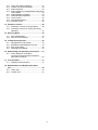
TABLE OF CONTENTS
1. Safety Precautions.............................................3
2. Specification .......................................................5
3. Features ..............................................................8
4. Location of Controls and Components ...........9
4.1 Indoor Unit....................................................9
4.2 Outdoor Unit.................................................9
4.3 Remote Control ............................................9
5. Dimensions.......................................................10
5.1 Indoor Unit..................................................10
5.2 Outdoor Unit...............................................11
6. Refrigeration Cycle Diagram...........................12
7. Block Diagram ..................................................13
8. Wiring Connection Diagram............................14
8.1 Indoor Unit..................................................14
8.2 Outdoor Unit ...............................................15
9. Electronic Circuit Diagram ..............................16
9.1 Indoor Unit..................................................16
9.2 Outdoor Unit ...............................................17
10. Printed Circuit Board .......................................18
10.1 Indoor Unit..................................................18
10.2 Outdoor Unit ...............................................20
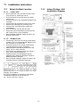
11. Installation Instruction.....................................22
11.1 Select the Best Location ............................22
11.2 Indoor/Outdoor Unit Installation Diagram...22
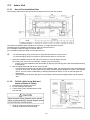
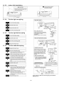
11.3 Indoor Unit..................................................23
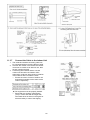
11.4 Outdoor Unit ...............................................27
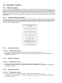
12. Operation Control.............................................30
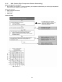
12.1 Basic Function............................................30
PRECAUTION OF LOW TEMPERATURE
In order to avoid frostbite, be assured of no refrigerant leakage during the installation or repairing of refrigerant circuit.
WARNING
This service information is designed for experienced repair technicians only and is not designed for use by the general public.
It does not contain warnings or cautions to advise non-technical individuals of potential dangers in attempting to service a product.
Products powered by electricity should be serviced or repaired only by experienced professional technicians. Any attempt to
service or repair the products dealt with in this service information by anyone else could result in serious injury or death.

2
12.2
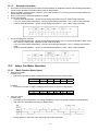
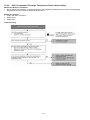
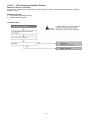
Indoor Fan Motor Operation .......................31
12.3 Outdoor Fan Motor Operation ....................32
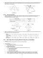
12.4 Airflow Direction..........................................32
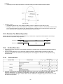
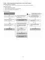
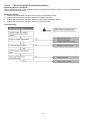
12.5 Quiet Operation (Cooling Mode/Cooling Area
of Dry Mode)...............................................33
12.6 Quiet Operation (Heating) ..........................34
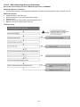
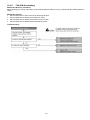
12.7 Powerful Mode Operation...........................34
12.8 Timer Control..............................................35
12.9 Auto Restart Control...................................35
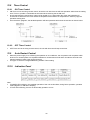
12.10 Indication Panel ..........................................35
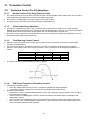
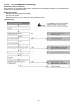
13. Protection Control ............................................36
13.1 Protection Control For All Operations.........36
13.2 Protection Control For Cooling & Soft Dry
Operation....................................................37
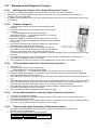
14. Servicing Mode .................................................40
14.1 Auto Off/On Button .....................................40
14.2 Remote Control Button...............................41
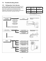
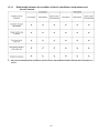
15. Troubleshooting Guide....................................42
15.1 Refrigeration Cycle System........................42
15.2 Breakdown Self Diagnosis Function...........44
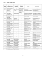
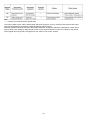
15.3 Error Code Table........................................45
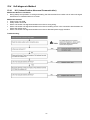
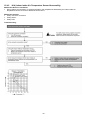
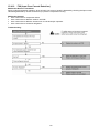
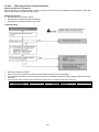
15.4 Self-diagnosis Method................................47
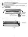
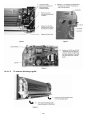
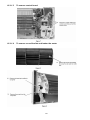
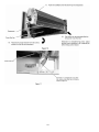
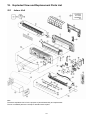
16. Disassembly and Assembly Instructions ......67
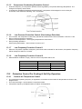
16.1 Indoor Electronic Controllers,
Cross Flow Fan and Indoor Fan Motor
Removal Procedures ..................................67
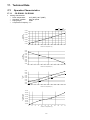
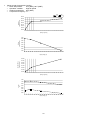
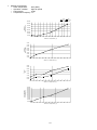
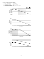
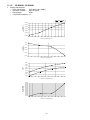
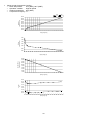
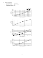
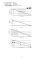
17. Technical Data ..................................................71
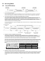
17.1 Operation Characteristics...........................71
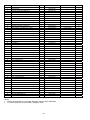
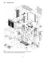
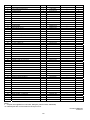
18. Exploded View and Replacement Parts
List .....................................................................79
18.1 Indoor Unit ..................................................79
18.2 Outdoor Unit ...............................................81

3
CAUTION
WARNING
WARNING
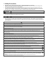
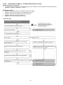
1. Safety Precautions
Read the following “SAFETY PRECAUTIONS” carefully before perform any servicing.
Electrical work must be installed or serviced by a licensed electrician. Be sure to use the correct rating of the
power plug and main circuit for the model installed.
The caution items stated here must be followed because these important contents are related to safety. The
meaning of each indication used is as below. Incorrect installation or servicing due to ignoring of the instruction
will cause harm or damage, and the seriousness is classified by the following indications.
This indication shows the possibility of causing death or serious injury
This indication shows the possibility of causing injury or damage to properties.
The items to be followed are classified by the symbols:
Carry out test run to confirm that no abnormality occurs after the servicing. Then, explain to user the operation,
care and maintenance as stated in instructions. Please remind the customer to keep the operating instructions for
future reference.
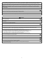
1. Do not modify the machine, part, material during repairing service.
2. If wiring unit is supplied as repairing part, do not repair or connect the wire even only partial wire break. Exchange the whole wiring unit.
3. Do not wrench the fasten terminal. Pull it out or insert it straightly.
4. Engage authorized dealer or specialist for installation and servicing. If installation of servicing done by the user is defective, it will cause water
leakage, electrical shock or fire.
5. Install according to this installation instructions strictly. If installation is defective, it will cause water leakage, electric shock or fire.
6. Use the attached accessories parts and specified parts for installation and servicing. Otherwise, it will cause the set to fall, water leakage, fire
or electrical shock.
7. Install at a strong and firm location which is able to withstand the set’s weight. If the strength is not enough or installation is not properly done,
the set will drop and cause injury.
8. For electrical work, follow the local national wiring standard, regulation and the installation instruction. An independent circuit and single outlet
must be used. If electrical circuit capacity is not enough or defect found in electrical work, it will cause electrical shock or fire.
9. This equipment is strongly recommended to be installed with Earth Leakage Circuit Breaker (ELCB) or Residual Current Device (RCD).
Otherwise, it may cause electrical shock and fire in case equipment breakdown or insulation breakdown.
10. Do not use joint cable for indoor/outdoor connection cable. Use the specified indoor/outdoor connection cable, refer to installation instruction
CONNECT THE CABLE TO THE INDOOR UNIT and connect tightly for indoor/outdoor connection. Clamp the cable so that no external force
will be acted on the terminal. If connecting or fixing is not perfect, it will cause heat up or fire at the connection.
11. Wire routing must be properly arranged so that control board cover is fixed properly. If control board cover is not fixed perfectly, it will cause
heat-up or fire at the connection point of terminal, fire or electrical shock.
12. When install or relocate air conditioner, do not let any substance other than the specified refrigerant, eg. air etc. mix into refrigeration cycle
(piping). (Mixing of air etc. will cause abnormal high pressure in refrigeration cycle and result in explosion, injury etc.).
13. Do not install outdoor unit near handrail of veranda. When installing air-conditioner unit at veranda of high rise building, child may
climb up to outdoor unit and cross over the handrail and causing accident.
14. This equipment must be properly earthed. Earth line must not be connected to gas pipe, water pipe, earth of lightning rod and
telephone. Otherwise, it may cause electrical shock in case equipment breakdown or insulation breakdown.
15. Keep away from small children, the thin film may cling to nose and mouth and prevent breathing.
16. Do not use unspecified cord, modified cord, joint cord or extension cord for power supply cord. Do not share the single outlet with
other electrical appliances. Poor contact, poor insulation or over current will cause electrical shock or fire.
17. Tighten the flare nut with torque wrench according to specified method. If the flare nut is over-tightened, after a long period, the flare may
break and cause refrigerant gas leakage.
18. For R410A models, when connecting the piping, do not use any existing (R22) pipes and flares nuts. Using such same may cause
abnormally high pressure in the refrigeration cycle (piping), and possibly result in explosion and injury. In case of using existing (R22)
pipes during installation of R410A models, must carry out pump down properly to collect back the refrigerant and oil before installation
new unit.
Thickness of copper pipes used with R410A must be more than 1/64". Never use copper pipes thinner than 1/64".
It is desirable that the amount of residual oil is less than 0.0006 oz/ft.
This symbol denotes item that is PROHIBITED from doing.

4
CAUTION
19. During installation, install the refrigerant piping properly before run the compressor. (Operation of compressor without fixing refrigeration piping
and valves at opened condition will cause suck-in of air, abnormal high pressure in refrigeration cycle and result in explosion, injury etc.).
20. During pump down operation, stop the compressor before remove the refrigeration piping. (Removal of refrigeration piping while compressor is
operating and valves are opened condition will cause suck-in of air, abnormal high pressure in refrigeration cycle and result in explosion, injury
etc.).
21. After completion of installation or service, confirm there is no leakage of refrigerant gas. It may generate toxic gas when the refrigerant
contacts with fire.
22. Ventilate if there is refrigerant gas leakage during operation. It may cause toxic gas when the refrigerant contacts with fire.
23. Do not insert your fingers or other objects into the unit, high speed rotating fan may cause injury.
24. Must not use other parts except original parts describe in catalog and manual.
25. Using of refrigerant other than the specified type may cause product damage, burst and injury etc.
1. Do not install the unit at place where leakage of flammable gas may occur. In case gas leaks and accumulates at surrounding of the
unit, it may cause fire.
2. Carry out drainage piping as mentioned in installation instructions. If drainage is not perfect, water may enter the room and damage
the furniture.
3. Tighten the flare nut with torque wrench according to specified method. If the flare nut is over-tightened, after a long period, the flare
may break and cause refrigerant gas leakage.
4. Do not touch outdoor unit air inlet and aluminium fin. It may cause injury.
5. Select an installation location which is easy for maintenance.
6. Pb free solder has a higher melting point than standard solder; typically the melting point is 50°F – 70°F (30°C – 40°C) higher. Please use
a high temperature solder iron. In case of the soldering iron with temperature control, please set it to 700 ± 20°F (370 ± 10°C).
Pb free solder will tend to splash when heated too high (about 1100°F / 600°C).
7. Power supply connection to the room air conditioner.
Power supply cord shall be UL listed or CSA approved 3 conductor with minimum AWG12 wires.
Power supply point should be in an easily accessible place for power disconnection in case of emergency.
In some countries, permanent connection of this air conditioner to the power supply is prohibited.
Fix power supply connection to a circuit breaker for the permanent connection.
Use NRTL approved fuse or circuit breaker (rating refers to name plate) for the permanent connection.
8. Do not release refrigerant during piping work for installation, servicing, reinstallation and during repairing a refrigerant parts. Take
care of the liquid refrigerant, it may cause frostbite.
9. Installation or servicing work: It may need two people to carry out the installation or servicing work.
10. Do not install this appliance in a laundry room or other location where water may drip from the ceiling, etc.
11. Do not sit or step on the unit, you may fall down accidentally.
12. Do not touch the sharp aluminium fins or edges of metal parts.
If you are required to handle sharp parts during installation or servicing, please wear hand glove.
Sharp parts may cause injury.

5
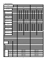
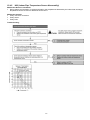
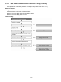
2. Specification
Indoor CS-E18NKUA CS-E24NKUA
Model
Outdoor CU-E18NKUA CU-E24NKUA
Performance Test Condition ARI ARI
Phase, Hz Single, 60 Single, 60
Power Supply
V 208 230 208 230
Min. Mid. Max. Min. Mid. Max. Min. Mid. Max. Min. Mid. Max.
kW 1.70 5.01 5.80 1.70 5.01 5.80 1.70 7.02 8.00 1.70 7.02 8.00
Capacity
BTU/h 5800 17100 19800 5800 17100 19800 5800 24000 27200 5800 24000 27200
Running Current A - 7.20 - - 6.30 - - 11.90 - - 10.80 -
Input Power W 430 1.30k 1.60k 430 1.30k 1.60k 430 2.35k 2.72k 430 2.35k 2.72k
W/W 3.95 3.85 3.63 3.95 3.85 3.63 3.95 2.99 2.94 3.95 2.99 2.94
EER
Btu/hW 13.45 13.15 12.35 13.45 13.15 12.35 13.45 10.20 10.00 13.45 10.20 10.00
Power Factor % - 87 - - 90 - - 95 - - 95 -
dB-A 47 / 39 / 36 47 / 39 / 36 48 / 40 / 37 48 / 40 / 37
Indoor Noise (H / L / QLo)
Power Level dB 63 / - / - 63 / - / - 64 / - / - 64 / - / -
dB-A 49 / - / - 49 / - / - 51 / - / - 51 / - / -
Cooling
Outdoor Noise (H / L / QLo)
Power Level dB 63 / - / - 63 / - / - 65 / - / - 65 / - / -
kW 1.70 6.00 6.10 1.70 6.00 6.10 1.70 8.46 8.56 1.70 8.46 8.56
Capacity
BTU/h 5800 20400 20800 5800 20400 20800 5800 28800 29200 5800 28800 29200
Running Current A - 8.60 - - 7.50 - - 12.60 - - 11.40 -
Input Power W 380 1.60k 1.65k 380 1.60k 1.65k 380 2.50k 2.66k 380 2.50k 2.66k
W/W 4.47 3.74 3.70 4.47 3.75 3.70 4.47 3.38 3.22 4.47 3.38 3.22
COP
Btu/hW 15.25 12.75 12.60 15.25 12.75 12.60 15.25 11.50 10.95 15.25 11.50 10.95
Power Factor % - 89 - - 93 - - 95 - - 95 -
dB-A 46 / 39 / 36 46 / 39 / 36 48 / 40 / 37 48 / 40 / 37
Indoor Noise (H / L / QLo)
Power Level dB 62 / - / - 62 / - / - 64 / - / - 64 / - / -
dB-A 51 / - / - 51 / - / - 53 / - / - 53 / - / -
Heating
Outdoor Noise (H / L / QLo)
Power Level dB 65 / - / - 65 / - / - 67 / - / - 67 / - / -
Max Current (A) / Max Input Power (W) 11.6 / 2.49k 13.7 / 3.06k
Starting Current (A) 8.6 12.6
Min Circuit Ampacity 15.0 20.0
Max. Overcurrent Protection 20.0 25.0
SEER / HSPF 18.00 / 8.50 17.50 / 8.50
Type Hermetic Motor / Rotary Hermetic Motor / Rotary
Motor Type Brushless (4 poles) Brushless (4 poles)
Compressor
Output Power W 1.7k 1.7k
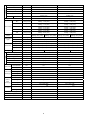
Type Cross-flow fan Cross-flow fan
Material ASG30K1 ASG30K1
Motor Type Transistor (8 poles) Transistor (8 poles)
Input Power W 94.8 - 94.8 94.8 - 94.8
Output Power W 40 40
QLo rpm
Cooling : 990
Heating : 1060
Cooling : 1020
Heating : 1150
Lo rpm
Cooling : 1090
Heating : 1160
Cooling : 1120
Heating : 1270
Me rpm
Cooling : 1270
Heating : 1330
Cooling : 1300
Heating : 1430
Hi rpm
Cooling : 1460
Heating : 1500
Cooling : 1480
Heating : 1600
Indoor Fan
Speed
SHi rpm
Cooling : 1500
Heating : 1600
Cooling : 1600
Heating : 1600

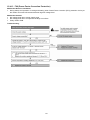
6
Type Propeller Propeller
Material PP PP
Motor Type DC Motor (8 poles) DC Motor (8 poles)
Input Power W - -
Output Power W 60 60
Outdoor Fan
Speed Hi rpm
Cooling: 700
Heating: 700
Cooling: 700
Heating: 750
Moisture Removal L/h (Pt/h) 1.4 (3.0) 3.6 (7.6)
QLo m
3
/min (ft
3
/min)
Cooling : 11.74 (410)
Heating : 12.88 (450)
Cooling : 11.97 (420)
Heating : 13.60 (480)
Lo m
3
/min (ft
3
/min)
Cooling : 13.15 (460)
Heating : 14.32 (500)
Cooling : 13.37 (470)
Heating : 15.25 (540)
Me m
3
/min (ft
3
/min)
Cooling : 15.71 (550)
Heating : 16.76 (590)
Cooling : 15.88 (560)
Heating : 17.45 (620)
Hi m
3
/min (ft
3
/min)
Cooling : 18.40 (650)
Heating : 19.20 (680)
Cooling : 18.40 (650)
Heating : 19.80 (700)
Indoor Airflow
SHi m
3
/min (ft
3
/min)
Cooling : 18.97 (670)
Heating : 20.64 (730)
Cooling : 20.07 (710)
Heating : 19.80 (700)
Outdoor
Airflow
Hi m
3
/min (ft
3
/min)
Cooling : 54.5 (1925)
Heating : 54.5 (1925)
Cooling : 54.5 (1925)
Heating : 54.5 (1925)
Cooling : 54.5 (1925)
Heating : 56.5 (1995)
Cooling : 54.5 (1925)
Heating : 56.5 (1995)
Control Device Expansion Valve Expansion Valve
Refrigerant Oil cm
3
FV50S (800) FV50S (800)
Refrigeration
Cycle
Refrigerant Type g (oz) R410A, 1.60k (56.5) R410A, 1.85k (65.3)
Height(I/D / O/D) mm (inch) 290 (11-7/16) / 795 (31-5/16) 290 (11-7/16) / 795 (31-5/16)
Width (I/D / O/D) mm (inch) 1070 (42-5/32) / 875 (34-15/32) 1070 (42-5/32) / 875 (34-15/32)
Dimension
Depth (I/D / O/D) mm (inch) 235 (9-9/32) / 320 (12-5/8) 235 (9-9/32) / 320 (12-5/8)
Weight Net (I/D / O/D) kg (lb) 12 (26) 60 (132) 12 (26) 60 (132)
Pipe Diameter (Liquid / Gas) mm (inch) 6.35 (1/4) / 12.70 (1/2) 6.35 (1/4) / 15.88 (5/8)
Standard length m (ft) 7.5 (24.6) 7.5 (24.6)
Length range (min – max) m (ft) 3 (9.8) ~ 30.5 (100.0) 3 (9.8) ~ 30.5 (100.0)
I/D & O/D Height different m (ft) 15 (49.2) 15 (49.2)
Additional Gas Amount g/m (oz/ft) 25 (0.3) 25 (0.3)
Piping
Length for Additional Gas m (ft) 10 (32.8) 10 (32.8)
Inner Diameter mm 16.7 16.7
Drain Hose
Length mm 650 650
Fin Material Aluminium (Pre Coat) Aluminium (Pre Coat)
Fin Type Slit Fin Slit Fin
Row x Stage x FPI 2 x 15 x 21 2 x 15 x 21
Indoor Heat
Exchanger
Size (W x H x L) mm 25.4 x 315 x 810 25.4 x 315 x 810
Fin Material Aluminium (Blue coated) Aluminium (Blue coated)
Fin Type Corrugate Fin Corrugate Fin
Row x Stage x FPI 2 x 36 x 19 2 x 36 x 19
Outdoor
Heat
Exchanger
Size (W x H x L) mm
36.4 x 756 x 869
897
36.4 x 756 x 869
897
Material Polypropelene Polypropelene
Air Filter
Type One-touch One-touch
Power Supply Outdoor Outdoor
Power Supply Cord A - -
Thermostat - -
Protection Device - -

7
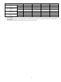
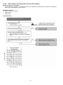
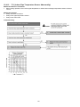
DRY BULB WET BULB DRY BULB WET BULB
Maximum 89.6 73.4 89.6 73.4
Indoor Operation Range
(Cooling)
Minimum 60.8 51.8 60.8 51.8
Maximum 109.4 78.8 109.4 78.8
Outdoor Operation Range
(Cooling)
Minimum 0.0 - 0.0 -
Maximum 86.0 - 86.0 -
Indoor Operation Range
(Heating)
Minimum 60.8 - 60.8 -
Maximum 75.2 64.4 75.2 64.4
Outdoor Operation Range
(Heating)
Minimum 5.0 3.2 5.0 3.2
1. Cooling capacities are based on indoor temperature of 80°F DRY BULB, 67°F WET BULB and outdoor air temperature of 95°F DRY BULB,
75°F WET BULB.
2. Heating capacities are based on indoor temperature of 70°F DRY BULB, 60°F WET BULB and outdoor air temperature of 47°F DRY BULB,
43°F WET BULB.
3. Specifications are subjected to change without prior notice for further improvement.

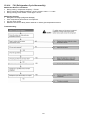
8
3. Features
Inverter Technology
o Wider output power range
o Energy saving
o Quick Cooling
o More precise temperature control
Environment Protection
o Non-ozone depletion substances refrigerant (R410A)
Long Installation Piping
o Long piping up to 100 foot
Easy to use remote control
Quality Improvement
o Random auto restart after power failure for safety restart operation
o Gas leakage protection
o Prevent compressor reverse cycle
o Inner protector to protect Compressor
o Noise prevention during soft dry operation
Operation Improvement
o Quiet mode to reduce the indoor unit operating sound
o Powerful mode to reach the desired room temperature quickly
Serviceability Improvement
o Breakdown Self Diagnosis function

9
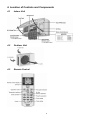
4. Location of Controls and Components
4.1 Indoor Unit
4.2 Outdoor Unit
4.3 Remote Control

10
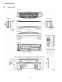
5. Dimensions
5.1 Indoor Unit

11
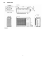
5.2 Outdoor Unit

12
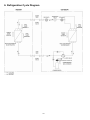
6. Refrigeration Cycle Diagram

13
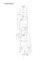
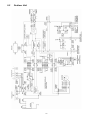
7. Block Diagram

14
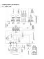
8. Wiring Connection Diagram
8.1 Indoor Unit

15
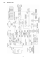
8.2 Outdoor Unit

16
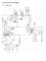
9. Electronic Circuit Diagram
9.1 Indoor Unit

17
9.2 Outdoor Unit

18
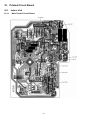
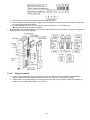
10. Printed Circuit Board
10.1 Indoor Unit
10.1.1 Main Printed Circuit Board

19
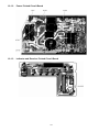
10.1.2 Power Printed Circuit Board
10.1.3 Indicator and Receiver Printed Circuit Board

20
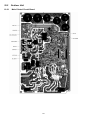
10.2 Outdoor Unit
10.2.1 Main Printed Circuit Board
Page is loading ...
Page is loading ...
Page is loading ...
Page is loading ...
Page is loading ...
Page is loading ...
Page is loading ...
Page is loading ...
Page is loading ...
Page is loading ...
Page is loading ...
Page is loading ...
Page is loading ...
Page is loading ...
Page is loading ...
Page is loading ...
Page is loading ...
Page is loading ...
Page is loading ...
Page is loading ...
Page is loading ...
Page is loading ...
Page is loading ...
Page is loading ...
Page is loading ...
Page is loading ...
Page is loading ...
Page is loading ...
Page is loading ...
Page is loading ...
Page is loading ...
Page is loading ...
Page is loading ...
Page is loading ...
Page is loading ...
Page is loading ...
Page is loading ...
Page is loading ...
Page is loading ...
Page is loading ...
Page is loading ...
Page is loading ...
Page is loading ...
Page is loading ...
Page is loading ...
Page is loading ...
Page is loading ...
Page is loading ...
Page is loading ...
Page is loading ...
Page is loading ...
Page is loading ...
Page is loading ...
Page is loading ...
Page is loading ...
Page is loading ...
Page is loading ...
Page is loading ...
Page is loading ...
Page is loading ...
Page is loading ...
Page is loading ...
-
 1
1
-
 2
2
-
 3
3
-
 4
4
-
 5
5
-
 6
6
-
 7
7
-
 8
8
-
 9
9
-
 10
10
-
 11
11
-
 12
12
-
 13
13
-
 14
14
-
 15
15
-
 16
16
-
 17
17
-
 18
18
-
 19
19
-
 20
20
-
 21
21
-
 22
22
-
 23
23
-
 24
24
-
 25
25
-
 26
26
-
 27
27
-
 28
28
-
 29
29
-
 30
30
-
 31
31
-
 32
32
-
 33
33
-
 34
34
-
 35
35
-
 36
36
-
 37
37
-
 38
38
-
 39
39
-
 40
40
-
 41
41
-
 42
42
-
 43
43
-
 44
44
-
 45
45
-
 46
46
-
 47
47
-
 48
48
-
 49
49
-
 50
50
-
 51
51
-
 52
52
-
 53
53
-
 54
54
-
 55
55
-
 56
56
-
 57
57
-
 58
58
-
 59
59
-
 60
60
-
 61
61
-
 62
62
-
 63
63
-
 64
64
-
 65
65
-
 66
66
-
 67
67
-
 68
68
-
 69
69
-
 70
70
-
 71
71
-
 72
72
-
 73
73
-
 74
74
-
 75
75
-
 76
76
-
 77
77
-
 78
78
-
 79
79
-
 80
80
-
 81
81
-
 82
82


Panasonic CS-E24NKUA User manual
- Category
- Split-system air conditioners
- Type
- User manual
- This manual is also suitable for
Ask a question and I''ll find the answer in the document
Finding information in a document is now easier with AI
Related papers
-
Panasonic CS-E12NKUAW User manual
-
Panasonic CS-ME7QKUA Installation guide
-
Panasonic CS-DE25TKE1 Klimagerät Owner's manual
-
-
-
-
-
-
-
Panasonic CU-V24CTP5 Owner's manual
Other documents
-
 Cool Components GR-45-BLK Owner's manual
-
 Sea Breeze 18H43ZGX User manual
-
 Elitex TAC-12CHSA series User manual
-
Johnson Controls Mini VRF Heat Pump Outdoor Unit Single Phase 208/230V User manual
-
Airwell MD 35 Technical Instruction Manual
-
Shivaki SRH-P076DC User manual
-
KDK 3012UA User manual
-
LG LA120HSV2KIT Engineering Data
-
Haier 3U55S2SR2FA User manual
-
LG Electronics 5CSV2-03A User manual


