Thermador Char-Glo CGBD30RX User manual
- Category
- Cookers
- Type
- User manual
This manual is also suitable for

Installation Instructions
for
Thermador Char Glo
®
Outdoor Barbecues
Installer: Please leave these instructions with the unit for the owner.
Owner: Please retain these instructions for future reference.
CGBD48RSBX
AVERTISSEMENT: Si l’information dans ce manuel n’est pas suivie exactement,
une incendie ou une explosion peut résulter, entrainant des dégats matériels, des
blessures ou la mort.
▲
!
WARNING: If the information in this manual is not followed exactly, a fire or
explosion may result causing property damage, personal injury or death.
▲
!
Models:
CGBD30RX • CGBD36RX
CGBD48RSBX • CGBD48RX
CGBD30RX
CGBD36RX
Page is loading ...

Page1
Contents
SECTION 1: Safety Information ................................................................. 2
SECTION 2: Gas Requirements................................................................... 3
Natural Gas Requirements .......................................................................... 3
Propane Gas Requirements ......................................................................... 3
Gas Consumption .......................................................................................... 3
Propane Hook-up .......................................................................................... 3
SECTION 3: Site Preparation...................................................................... 5
Built-In Installations ....................................................................................... 5
Cabinet Preparation ...................................................................................... 5
SECTION 4: Electrical Cautions .................................................................. 7
Electrical Requirements ................................................................................ 7
Grounding Instructions................................................................................. 7
SECTION 5: Unpacking, Moving and Placing the Unit ....................8 - 10
Locating your Char Glo
®
Barbecue ........................................................... 8
Liquid Propane to Natural Gas Conversion .......................................... 10
Gas and Electrical Hook-up ....................................................................... 11
Side Panel Installation.................................................................................. 11
SECTION 6: Test and Adjustment.............................................................. 12
Checking for Leaks ...................................................................................... 12
Burner Air Adjustment................................................................................ 12
Installer Checklist......................................................................................... 12
Installation...................................................................................................... 12
Gas Supply ..................................................................................................... 12
Electrical ......................................................................................................... 12

Page 2
TESTED IN ACCORDANCE WITH ANSI Z21.58 – 1995, ANSI Z21.58a – 1998 STANDARD FOR
OUTDOOR COOKING GAS APPLIANCES, AND CAN/CGA 1.6 – M95, CGA 1.6a – M98,
STANDARD FOR OUTDOOR COOKING GAS APPLIANCES.
This unit is for outdoor use only in a well-ventilated area. Not to be
used in a building, garage or any other enclosed area.
Check your local building codes for the proper method of installation. In the absence of local codes this
unit should be installed in accordance with the National Fuel Gas Code No. Z223.1 Current Issue and
National Electrical Code ANSI/NFPA No. 70 Current Issue or the CAN/CGA – B149.1 Natural Gas
Installation Code or CAN/CGA - B149.2 Propane Installation Code and C22.1 Canadian Electrical Code
Part1.
Installation and service must be performed by a qualified installer,
service agency or the gas supplier.
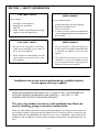
SECTION 1: SAFETY INFORMATION
FOR YOUR SAFETY
If you smell gas:
1. Shut off gas to the appliance.
2. Extinguish any open flame.
3. Open lid.
4. If odor continues, immediately call your gas
supplier or your fire department.
FOR YOUR SAFETY
1. Do not store or use gasoline or other flam-
mable vapors and liquids in the vicinity of
this or any other appliance.
2. An LP cylinder not connected for use shall
not be stored in the vicinity of this or any
other appliance.
AVERTISSEMENT
S’il y a une odeur de gaz:
1. Coupez l’admission de gaz de l’appariel.
2. Ènteindre toute flamme nue.
3. Ouvrir le couvercle.
4. Si l’odeur peraiste, appeler immediatement
votre compagnie de gaz ou votre departement
des incendies.
AVERTISSEMENT
1. Ne pas entreposer ni utiliser de l‘essence ni
d’autres vapeurs ou liquides inflammables dans
le voisinage de l’appareil, ni de tout autre
appareil.
2. Une bouteille de propane qui n’est pas
raccordée en vue de son utilisation, ne doit
pas etre entreposée dans le voisinage de cet
appareil ou de tout autre appareil.

Page 3
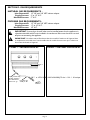
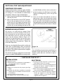
NATURAL GAS REQUIREMENTS -
Inlet Connection: 1/2" NP with 3/8" NPT reducer adapter.
Supply Pressure: 6" to 14" W.C.
Manifold Pressure: 5" W.C.
PROPANE GAS REQUIREMENTS -
Inlet Connection: 1/2" NP with 3/8" NPT reducer adapter.
Supply Pressure: 11" to 14" W.C.
Manifold Pressure: 10" W.C.
FIGURE 1 – PROPANE HOOK-UP
SECTION 2: GAS REQUIREMENTS
IMPORTANT: Un robinet manuel d'isolement doit étre installé à l’extérieur de l’appareil, dans
un emplacement accessible avec l’unité installée dans la module. Assurez-vous que le robinet est
fermé avant de brancher l’appareil.
▲
!
▲
!
IMPORTANT: A manual gas shut off valve must be installed external to the appliance, in
a location accessible with the unit installed in the enclosure. Make sure the valve is turned
off prior to connecting the appliance.
FIGURE 2 – NATURAL GAS HOOK-UP
Bottom of
unit
➞
Coupling 1/2" NPT fitting
threading compound on
these threads must be
resistant to LP gas
L.P. Regulator hose
assembly 10" W.C.
➚
➚77HOOt 2.h0 TJ99m -d-ET11r3 0.0002 -0.0t2133ecCc06-20N1r()Tj/F valve is 39.04 -719.04 resadapter.

For Massachusetts Installations:
1. Shut-off valve must be a “T” handle gas cock.
2. Flexible gas connector must not be longer than 36 inches.
3. Not approved for installation in a bedroom or a bathroom unless unit is direct vent.
SECTION 2: GAS REQUIREMENTS
Page 4
CAUTION: The appliance must be isolated from the gas supply system by closing its
individual manual shut-off valve during any pressure testing of the gas supply
piping system at test pressures equal to or less than 1/2" psig (3.5kPa).
When checking the manifold gas pressure, the inlet pressure to the appliance
regulator should be at least 7.0" W.C. for natural gas, and 11.0" W.C. for
propane.
Do not attempt any adjustment of the pressure regulator.
ATTENTION: L’appareil doit étre isolé du circuit d’alimentation de gaz en fermant son
rob1net manuel d’isolement individuel pendant toutes essais sous pression
du circuit de tuyauterie d’alimentation de gaz aux pressions d’essai égales à
ou moins de 3.5kPa (1/2 psig).
En controlant la pression de gaz du tubulure, la pression de prise au
régulateur de l’appareil devrait étre au moins 11.2mm HG pour gaz naturel,
et 20.5mm HG pour gaz de propane.
N’essayez aucun réglage du régulateur de pression.
CAUTION: When connecting to propane gas supply, make certain that the propane gas
tank is equipped with its own high pressure regulator in addition to the
pressure regulator supplied with the appliance. The pressure of the gas at the
appliance regulator must not exceed 14" water column.
ATTENTION: En se reliant a l approvisionnement de gaz de propane, assurez-vous que le
réservoir de gaz de propane est équipé de son Propre régulateur à haute
pression en peus du régulateur de Pression fourni avec l’appareil. La pression
du gaz au régulateur de l’appareil ne doit pas exéceder 26.1 mm HG.

Page 5
SECTION 3: SITE PREPARATION
BUILT-IN INSTALLATIONS
All Char-Glo
®
Outdoor Barbecues
are CGA and AGA approved.
Note: All height width and depth dimensions are shown in inches.
Determine a suitable location for the barbecue by taking into account exposure to wind and availability of gas and
electrical supplies. Exposure to wind should be minimized, as wind can adversely affect cooking performance. Insure
that the gas supply line and electrical supply are located in close proximity to the unit to keep connections to the
unit as short as possible and allow for installation and removal of the unit from the enclosure. Allow adequate area
around the unit for dissipation of smoke produced during cooking.
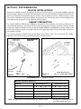
CLEARANCES (Refer to Figures 3 and 4)
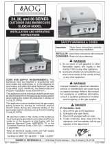
CABINET PREPARATION
The models CGBD30, CGBD36 and CGBD48 are designed for easy installation into masonry enclosures. For
noncombustible applications, the barbecue drops into the opening shown in Figures 3 and Fig. 4, (below). A ledge
is required to support the barbecue from the bottom. Models CGBD36 and CGBD48 also require a ledge in the
center of the opening to support the middle of the unit. The supporting ledges must be level and flat. The counter
top should also be level.
It
is recommended that ventilation holes are provided in the enclosure in the event of a gas leak. The installer-
supplied gas shut-off valve must be installed in an easily accessible location.
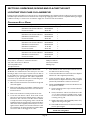
CharGlo
®
Outdoor Barbecues
Model No. Overall Dimensions Cutout Dimensions
ABC DEF
CGBD30RX 24-
3
/4 30-
7
/16 26-
5
/8 11-
15
/16 29-
3
/4 22-
3
/4
CGBD36RX 24-
3
/4 36 26-
5
/8 11-
15
/16 35-
5
/16 22-
3
/4
CGBD48RSBX 24-
3
/4 48 26-
5
/8 11-
15
/16 47-
5
/16 22-
3
/4
CGBD48RX 24-
3
/4 48 26-
5
/8 11-
15
/16 47-
5
/16 22-
3
/4
Figure 3
Figure 4
C
E
F
B
A
3" minimum for
hood clearance
to back wall
Cutout Dimensions for
30", 36" and 48" Built-in Units
D
F
E
OPENING FOR
ACCESS DOOR
➞
GAS
INLET
3" MINIMUM FOR
LID CLEARANCE
36
"
12"
NON-COMBUSTIBLE
ENCLOSURE
12"
12"
Properly Grounded
3-Prong Receptacle
36
Center Support
Ledge for
CGBD36 and CGBD48

Page 6
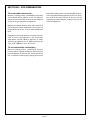
SECTION 3: SITE PREPARATION
To combustible construction -
Below the cooking surface, combustible construction
can be placed directly adjacent to the unit. Allow 8"
clearance at the lower left rear of the unit for adequate
routing of the gas and electrical supply line.
Minimum horizontal clearance from sides and back of
unit to adjacent vertical combustible construction ex-
tending above top of unit, 12" from sides and 20" from
back.
Degagement horizontal minimal a respecter entre les
cotes et l’arriere de l’appareil et une construction
combustible verticale adjacent depassant la partie
superieure de l’appareil, soit 12" (305mm) pounces des
cotes et 20" (508mm) ponces de l’arriere.
To non-combustible construction -
Above the cooking surface, a minimum 8" clearance
from the sides is required to allow use of the rotisserie
motor and skewer. A minimum of 3" clearance from the
rear is required to allow proper opening of the hood.
Below the cooking surface, non-combustible construc-
tion can be placed directly adjacent to the unit. Clear-
ance of 8" at the lower left rear of the unit must be
maintained to allow adequate routing of the gas and
electrical supply lines.

Page 7
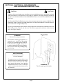
Installation of electrical supply circuit should be done by a qualified electrician in accordance with local
codes and ordinances. In the absence of local codes or ordinances, the supply should be installed in
accordance with the National Electric Code ANSI/NFPA No. 70, current issue, or Canadian Electric Code
C22.1 Part 1.
The Thermador® Char Glo® barbecues use an electronic ignition system that requires a 120 VAC, 15A,
60 Hz power supply. A properly grounded duplex outlet must be provided adjacent to the lower left rear
corner of the unit. See Figure 5A (below).
A properly grounded duplex outlet made for outdoor applications should also be provided above the level
of the cooking surface on the left side of the unit. This outlet is required for connection of the rotisserie
motor. See Figure 3 (Page 5).
CAUTION CAUTION
SECTION 4: ELECTRICAL REQUIREMENTS
AND GROUNDING INSTRUCTIONS
WARNING
Electrical Grounding Instructions
This outdoor cooking gas appliance is
equipped with a three-prong (grounding)
plug for your protection against shock haz-
ard and should be plugged directly into a
properly grounded three-prong receptacle.
Do not cut or remove the grounding prong
from this plug.
BARBECUE
Three-Prong Plug and Receptacle
AVERTISSEMENT
Instruction pour la mise
a la terre electrique
Cet appareil est muni d’une fiche a trots
broches (mise a la terre) afin de vous proteger
des chocs et doit etre branche dire~ement
dans une prise de courant a trots broches
adequatement mise a la tem. II ne faut pas
couper ou enlever la broche de mise a la tem
de cette fiche.
Figure 5A

Page 8
SECTION 5: UNPACKING, MOVING AND PLACING THE UNIT
Leaving the unit on the pallet, move the unit close to the final installation site. Unpack and remove all accessory items, packing
materials and product literature from inside the unit. Verify the gas supply type. If the unit is not compatible with the gas supply,
it will be necessary to convert it for use with the supply. See conversion instructions below.
LOCATING YOUR CHAR GLO
®
BARBECUE
Natural Gas to Liquid Propane Conversion
All Models are manufactured at the factory for use with
natural gas, and as such require conversion for use with an
LP gas supply. The conversion should be done by a qualified
technician or your gas supplier. All orifices required for
conversion are provided with the units. The following steps
are necessary to convert for LP operation -
1. Make sure that the unit is disconnected from the gas and
electrical supplies.
2. Remove the grill grates and radiants. Unbolt the main
burners from their attachment at the rear of the burner
box and remove.
3. Remove the knobs and control panel from the unit.
4. Locate the main burner orifices. From inside control
panel area, locate the brass elbows that the orifices are
attached to. Use a wrench on the flats of these elbows
to keep them from turning during orifice removal and
installation. Remove the main burner orifices and replace
with the LP orifices supplied (marked 54). Do not over-
tighten orifices. Orifice must extend a minimum of 1/8"
into main burner air shutter with burner installed. Make
sure burner will not disengage from orifice.
CONVERSION KIT BY MODEL
Model No. Orifice Description Part Number Quantity Remarks
CGBD30RX #54 Orifice Hood, Grill Burner 08-04-082-05 2 To Convert LP to NG
#59 Orifice Hood, Infrared Burner 08-04-082-02 1
Conversion Sticker 20-09-337 1
CGBD36RX #54 Orifice Hood, Grill Burner 08-04-082-05 3 To Convert NG to LP
#59 Orifice Hood, Infrared Burner 08-04-082-02 1
#73 Orifice, Smoker Burner 08-04-066-04 1
Conversion Sticker 20-09-337 1
CGBD48RSBX #54 Orifice Hood, Grill Burner 08-04-082-05 3 To Convert NG to LP
#59 Orifice Hood, Infrared Burner 08-04-082-02 1
#73 Orifice, Smoker Burner 08-04-066-04 1
#56 Orifice ,Side Burner 15-10-186 2
Conversion Sticker 20-09-337 1
CGBD48RX #54 Orifice Hood, Grill Burner 08-04-082-05 4 To Convert NG to LP
#59 Orifice Hood, Infrared Burner 08-04-082-02 2
#73 Orifice, Smoker Burner 08-04-066-04 1
Conversion Sticker 20-09-337 1
Tools/Parts Required
Socket Driver-1/4" Drive, 3" minimum extension
3/16" Or 7 mm Socket or Wrench
1/2" Deep Well Socket
1/2" Open Wrench
Phillip Screwdriver
Slotted Screwdriver
Masking Tape
5. From behind the unit, remove the louvered cover on
the infrared rotis burner housing.
6. Locate the infrared burner orifice and remove. Replace
with the LP orifice supplied (marked 59).
7. Locate the smoker burner. Slide the orifice out of the
burner and remove. Replace with the LP orifice supplied
(marked 73). Reinstall the orifice into the burner.
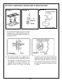
8. On Model CGBD48RSBX, convert the side burners for
LP operation as follows:
A. Remove the grate, burner caps, venturis and burner
bases. See Fig. 6.
B. Remove the burner orifices. Use a 7mm hex socket
on a 3" ratchet extension and apply a piece of tape
to the socket to hold the orifice in the socket while
removing. See Fig. 7A.
C. Replace with the LP orifices supplied (number 115).
Tighten until snug. See Fig 7B.
D. Reassemble the burner bases and venturis. Reinstall
burner caps and grate.
NOTE: Install the conversion sticker (supplied)
beside the rating label.

Page 9
SECTION 5: UNPACKING, MOVING AND PLACING THE UNIT
FIGURE 6
FIGURE 7A
FIGURE 7B
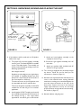
10. All barbecue models are supplied with a
pressure regulator that is packed with the unit.
The regulator is set for natural gas. For use
with propane, it must be converted. The
regulator will be located on the left rear
bottom of the unit. Using a flat blade
9. On all models, the bypass jet must be turned
clockwise with a small flat-bladed screwdriver
until fully seated to set proper low flow rate.
See Figures 8 and 9.
screwdriver, remove the cap on the top of the
regulator and turn the cap over so that the
letters LP are exposed. Make sure the spring
in the regulator remains in position. Re-attach
the cap to the regulator. See Figures 10 and
11, below.
FIGURE 8
FIGURE 9
TAPE

Page 10
11. If the barbecue will be used with an LP cylinder,
follow these steps:
C. The proper LP hose and regulator assembly
must be used. The Model LPHOSE is available
at your Thermador dealer. This assembly can
also be purchased locally providing it meets the
following specifications:
Hose length to be 24".
Regulator must be a high pressure, high volume
unit capable of supplying adequate gas flow
based on the input rating of the unit (refer to
Gas Consumption in Section 2).
The inlet connector on the LP regulator must
be compatible with the LP cylinder valve.
The hose and regulator assembly must be AGA
certified for use with LP gas in an outdoor
application.
B. Install supplied 1/2" NPT coupling on the end of
the manifold located at the left rear bottom of
the cooktop. See Fig. 1. Use a pipe sealant
approved for use with LP gases on all threads.
SECTION 5: UNPACKING, MOVING AND PLACING THE UNIT
C. Attach gas hose/regulator assembly to the
coupling as shown in Fig. 1.
D. Connect the gas regulator assembly to the LP
tank valve.
E. Attach gas regulator label (included with LP
orifices) to the gas regulator.
12. Turn on the gas supply but do not attempt to light
any burner. Check the unit for leaks per the
instructions in Section 6 (Page 12).
13. Reinstall control panel and knobs. Reinstall the rear
cover on the infrared burner housing. Reinstall
main burners, making sure to install and tighten the
nuts that retain the burners at the rear of the
burner box. Connect the unit to the electrical
supply. Light all burners one by one and verify
proper operation on high and low control settings.
See Section 6 (Page 12).
14. Reinstall radiants and grill grates.
FIGURE 10 FIGURE 11
Bottom of
unit
➞
Coupling 1/2" NPT fitting
threading compound on
these threads must be
resistant to LP gas
L.P. Regulator hose
assembly 10" W.C.
➚
➚
Type 1 Regulator
Regulator Adapter
➞
➞
➞
L.P. Tank
(Type 1)
➞
Main
Valve

Page 11
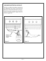
GAS AND ELECTRICAL HOOK-UP
With the unit inside of the enclosure, connect the
gas supply hose to the manual shut-off valve and
open valve. Check the connection points at the shut-
off valve for any leaks and repair prior to installation
of the unit. Connect the power supply cord to the
electrical supply outlet.
➞
LP Tank
Leak Test Points
Bottom of Unit
Check hose
for signs of
abrasions, cracks
or leaks
➞
Figure 12
Figure 13
Test Leak Points

Page 12
All points of connection to the gas supply should be
checked for leaks at time of installation or anytime
you smell gas. It is also advisable to recheck them
periodically. Follow the steps outlined below:
A. Make a soap solution of one part liquid detergent
and one part water.
B. Make sure all controls are in the "OFF" position.
Turn on the gas supply to the unit. Use a spray
bottle, brush or rag to apply the solution to all
fittings and points of connection from the supply
stub out up to and including the inlet to the
SECTION 6: TEST AND ADJUSTMENT
✓ INSTALLER CHECKLIST ✓
All burners are adjusted for proper flame
characteristics at time of assembly. If the unit has
been converted for use with alternate gas supply,
some adjustment of the air shutter on the main
burner may be necessary. Refer to Figure 14. If
adjustment is required, loosen the screw on the air
shutter and close or open shutter as required to
achieve proper flame characteristics. Tighten the
screw after adjustment.
All burners should exhibit flames which are blue and
stable, with no yellow-tipping, lifting or excessive
noise when operating on either natural or LP gases.
See Figure 8 for pictorial representation of proper
flame characteristics.
The infrared rotis burner, smoker burner and surface
burners on model CGBD48RSBX are not adjustable.
If any of the flame characteristics noted above are
observed, check the burner for dirt or residue in
the ports, spider webs, etc., and clean or repair as
necessary.
CHECKING FOR LEAKS
manifold. Bubbles will form where a leak exists.
C. If a leak is present, shut off the gas at the supply.
Tighten any leaking fittings, turn on the gas and
recheck.
D. If the unit has been converted for use with an
alternate gas, make sure the technician checks
for leaks at all points of connection in the control
panel area and at the infrared burner prior to
reassembly of the control panel and cover (Refer
to NG to LP Conversion, instructions in Section
5).
BURNER AIR ADJUSTMENT
ELECTRICAL
— Properly grounded receptacle is present for unit
and rotisserie motor as necessary.
— The burner box area is free of any packing materials
and that the burners, radiants and grates are
properly located and installed.
— Burner caps properly positioned and seated on
burner bases (Model CGBD48RSBX only).
— If the unit is to be used with propane gas, verify that
the LP gas supply has its own high pressure
regulator in addition to the pressure regulator
supplied with the appliance.
INSTALLATION
— Placement of unit.
— Specified clearances maintained to combustible or
noncombustible surfaces as applicable.
GAS SUPPLY
— Appliance is connected to the proper type of gas
supply.
— Manual gas shut off valve is installed in an accessible
location (with unit installed in enclosure for built-
in installations).
— Unit tested and free from gas leaks.
— Gas supply pressure does not exceed 14" W.C.
Figure 14

Inside Back Cover – Blank

5551 McFadden Avenue, Huntington Beach, CA 92649 • 800/735-4328
ECO 14028 • 08-04-439D • © BSH Home Appliances Corp. • Litho U. S. A. 4/01
Specifications are for planning purposes only. Refer to installation instructions and consult your countertop supplier prior to
making counter opening. Consult with a heating and ventilating engineer for your specific ventilation requirements. For the
most detailed information, refer to installation instructions accompanying product or write Thermador indicating the model
number.
Thermador reserves the right to change specifications or design without notice. Some models are certified for use in Canada.
Thermador is not responsible for products which are transported from the United States for use in Canada. Check with your
local Canadian distributor or dealer. Thermador, 5551 McFadden Avenue, Huntington Beach, CA 92649.
For the most up to date critical installation dimensions by fax, use your fax handset
and call 702/833-3600. Use code #8030.
-
 1
1
-
 2
2
-
 3
3
-
 4
4
-
 5
5
-
 6
6
-
 7
7
-
 8
8
-
 9
9
-
 10
10
-
 11
11
-
 12
12
-
 13
13
-
 14
14
-
 15
15
-
 16
16


Thermador Char-Glo CGBD30RX User manual
- Category
- Cookers
- Type
- User manual
- This manual is also suitable for
Ask a question and I''ll find the answer in the document
Finding information in a document is now easier with AI
Related papers
Other documents
-
Fire Magic Deluxe Drop In User manual
-
-
Twin Eagles TXBQ-26R-T Owner's manual
-
Bull Colt- Stallion- And Baron Gas Bbq Operating instructions
-
-
-
-
Barbeques Galore Turbo STS 750-0057-4BRB User manual
-
 American Outdoor 24NP Owner's manual
-
 American Outdoor 24NB Owner's manual

