GA-8VM800M Motherboard - 12 -
English
1-3 Installation of the CPU and Heatsink
Before installing the CPU, please comply with the following conditions:
1. Please make sure that the motherboard supports the CPU.
2. Please take note of the one indented corner of the CPU. If you install the CPU in the
wrong direction, the CPU will not insert properly. If this occurs, please change the
insert direction of the CPU.
3. Please add an even layer of heat sink paste between the CPU and heatsink.
4. Please make sure the heatsink is installed on the CPU prior to system use, otherwise
overheating and permanent damage of the CPU may occur.
5. Please set the CPU host frequency in accordance with the processor specifications. It
is not recommended that the system bus frequency be set beyond hardware
specifications since it does not meet the required standards for the peripherals. If you
wish to set the frequency beyond the proper specifications, please do so according to
your hardware specifications including the CPU, graphics card, memory, hard drive,
etc.
HT functionality requirement content :
Enabling the functionality of Hyper-Threading Technology for your computer system re-
quires all of the following platform components:
- CPU: An Intel
®
Pentium 4 Processor with HT Technology
- Chipset: An VIA Chipset that supports HT Technology
- BIOS: A BIOS that supports HT Technology and has it enabled
- OS: An operation system that has optimizations for HT Technology
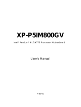
1-3-1 Installation of the CPU
Fig. 1
Position lever at a 90 degree angle.
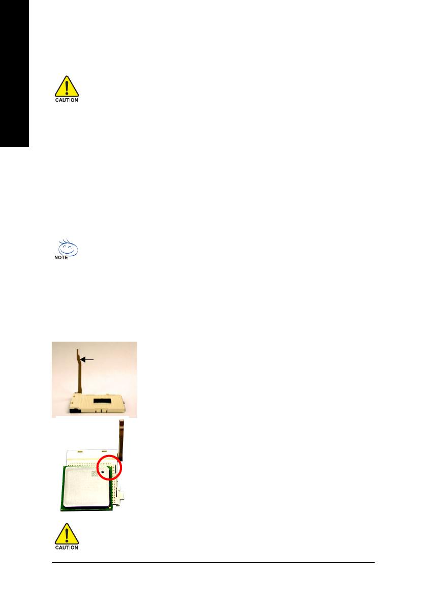
Fig. 2
A gold-colored triangle is marked one edge of the CPU. Please align this
edge with the socket edge closest to the CPU lever. Gently place the
CPU into position making sure that the CPU pins fit perfectly into their
holes.
Once the CPU is positioned into it socket, place one finger down on the
middle of the CPU and gently press the metal lever back into its original
position.
Socket lever
Please use extra care when installing the CPU. The CPU will not fit if positioned incorrectly.
Rather than applying force, please change the positioning of the CPU.