Vermont Casting VCBV20 User manual
- Category
- Fireplaces
- Type
- User manual

1
Vermont Castings VCBVMN/MP & VCPVMN/MP Room Heaters
Unvented
Gas-Fired Room Heater
Please read this manual
before installing and using
appliance.
WARNING: If the information in
this manual is not followed
exactly, a fire or explosion may
result causing property damage,
personal injury of loss of life.
• Do not store or use gasoline or
other flammable vapors and liquids in
the vicinity of this or any appliance.
• WHAT TO DO IF YOU SMELL GAS
• Do not try to light any appliance
• Do not touch any electrical switch;
do not use any phone in your building
• Immediately call your gas supplier
form a neighbor’s phone. Follow the
gas supplier’s instructions
• If you cannot reach your gas
supplier, call the fire department
• Installation and service must be
performed by a qualified installer,
service agency or the gas supplier.
INSTALLER / CONSUMER
SAFETY INFORMATION
Models: VCBV30MN, VCBV30MP - 30,000 Btu/Hr Manual
VCBV20MN, VCBV20MP - 20,000 Btu/Hr Manual
VCBV10MN, VCBV10MP - 10,000 Btu/Hr Manual
User’s Operation and Installation Manual
Installer: Leave this manual
with the consumer.
Consumer: Retain this
manual for future reference.
20003769 8/02 Rev. 1
VERMONT
C
astings
VERMONT
C
astings
VERMONT
C
astings
Models: VCPV30MN, VCPV30MP - 30,000 Btu/Hr Manual
VCPV18MN, VCPV18MP - 18,000 Btu/Hr Manual
VCPV10MN, VCPV10MP - 10,000 Btu/Hr Manual
VCPV06MN, VCPV06MP - 6,000 Btu/Hr Manual
Plaque Heaters
Blue Flame Heaters

2
Vermont Castings VCBVMN/MP & VCPVMN/MP Room Heaters
SAFETY: Accidents are always tragic, especially
because so many of them could have been prevented
with a little care and judgment. There are some basic
good practices we hope you will follow for safe use of
your gas fired room heater.
IMPORTANT: Read this user’s manual carefully and
completely before trying to assemble, operate or
service this heater. Improper use of this heater can
cause serious injury or death from burns, fire,
explosion, electrical shock and carbon monoxide
poisoning.
Early signs of carbon monoxide poisoning resembles
the flu, with headaches, dizziness or nausea. If you
have these signs, the heater may not be working
properly. Get fresh air at once! Have heater serviced.
Some people are more affected by carbon monoxide
than others. These include pregnant women, people
with heart or lung disease or anemia, those under the
influence of alcohol and those at high altitudes.
Begin by ensuring proper installation and servicing.
Follow the installation instructions provided with this
product. Have your heater installed by a qualified
technician. Have the installer show you where the gas
supply shut off valve is located so that you know where
to shut off the gas to the heater. If the connections are
not perfectly seated or tightened, you may have a leak
and therefore a faint gas smell.
Finding a leak is not a DO-IT-YOURSELF procedure.
Some leaks can only be found with the main burner gas
on and this must be done by a qualified technician.
General Safety Information
• This appliance is intended for supplemental heating.
• Never install the heater in any of the following
locations:
• Recreational vehicles
• Where curtains, furniture, clothing or other
flammable objects are less than 36” from the
front, top or sides of the heater
• Fireplace
• High traffic area
• Drafty areas
• This heater needs fresh, outside air for ventilation to
run properly. This heater has an oxygen depletion
sensor (ODS) pilot light safety system. The ODS
shuts down the heater if not enough fresh air/oxygen
content (18%) is available.
• Never run heater in confined space. Refer to Page 4.
• If heater shuts off, do not relight until you provide
fresh, outside air. If heater keeps shutting off, have it
serviced.
• Do not run the heater where:
• Flammable liquids or vapors are used or stored
• Dusty condition exists
• Never place any objects on the heater.
• Supervise children when they are in the same room
with heater, never allow them to sit, stand or play on
or around the heater.
• Make sure grille guard is in place before running
heater.
• Do not use heater if any part has been under water.
Immediately call a qualified service technician to
inspect the room heater and to replace any part of
the control system and any gas control which has
been under water.
• Keep appliance area clear and free from combus-
tible materials, gasoline and other flammable vapors
and liquids.
• Turn off heater and let cool before servicing. Only a
qualified technician should service and repair heater.
Table of Contents
General Safety Information ..................................... 2
Specifications .......................................................... 3
Installation ............................................................... 4
Operating Instructions ............................................. 8
Troubleshooting .................................................... 10
Maintenance...........................................................11
Replacement Parts................................................ 12
Accessories........................................................... 15
Precautions
• Never use natural gas in a unit designed for lique-
fied petroleum gases.
• Never use liquefied petroleum gases in a unit
designed for natural gas.
• Check all joints and connections. To avoid the
danger of fire, accident or explosion, never check a
potential gas leak with an open flame.
• The VCBV30, VCBV20, VCPV30 and VCPV18
heaters may not be installed in a bedroom or
bathroom.
• The VCBV10 and VCPV10 heaters may be
installed in a bedroom, but not a bathroom.
• The VCPV06 heaters may be installed in a bedroom
or bathroom.
WARNING:
This appliance is for use with gas referenced on
Rating Label. Field conversion is not permitted.

3
Vermont Castings VCBVMN/MP & VCPVMN/MP Room Heaters
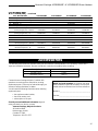
VCBVMN, VCBVMP, VCPVMN, VCPVMP Specifications
Input Rating Regulator Inlet Gas Supply Size
Gas (Btu/Hr) Variable Pressure Pressure of Heater Weight
VCBV30MN 15,000 30,000 27” x 24” x 8⁵⁄₈” 30 lbs.
VCBV20MN Natural 10,000 20,000 3.0” w.c. 7.0” w.c. 10.5” w.c. 19³⁄₈” x 22⁷⁄₈” x 8¹⁄₂” 22 lbs.
VCBV10MN 5,000 10,000 15¹⁄₂” x 20⁷⁄₁₆” x 7⁷⁄₈” 17 lbs.
VCBV30MP 15,000 30,000 27” x 24” x 8¹⁄₂” 30 lbs.
VCBV20MP LP 10,000 20,000 8.0” w.c. 11.0” w.c. 14.0” w.c. 19³⁄₈” x 22⁷⁄₈” x 8¹⁄₂” 22 lbs.
VCBV10MP 5,000 10,000 15¹⁄₂” x 20⁷⁄₁₆” x 7⁷⁄₈” 17 lbs.
VCPV30MN 6,400 30,000 27” X 24” X 8⁵⁄₈” 30 lbs.
VCPV18MN
Natural
6,400 18,000
6.0” w.c. 7.0” w.c. 10.5” w.c.
19³⁄₈” x 22⁷⁄₈” x 8¹⁄₂” 22 lbs.
VCPV10MN 5,500 10,000 15¹⁄₂” x 20⁷⁄₈” x 7⁷⁄₈” 17 lbs.
VCPV06MN 2,600 6,000 15¹⁄₂” x 20⁷⁄₈” x 7⁷⁄₈” 17 lbs.
VCPV30MP 6,400 30,000 27” x 24” x 8¹⁄₂” 30 lbs.
VCPV18MP
LP
6,400 18,000
10.0” w.c. 11.0” w.c. 14.0” w.c.
19³⁄₈” x 22⁷⁄₈” x 8¹⁄₂” 22 lbs.
VCPV10MP 5,500 10,000 15¹⁄₂” x 20⁷⁄₈” x 7⁷⁄₈” 17 lbs.
VCPV06MP 2,600 6,000 15¹⁄₂” x 20⁷⁄₈” x 7⁷⁄₈” 17 lbs.
NOTES: For altitudes above 2,000 feet, reduce the input ratings (Btu/Hr) 4% for each 1,000 feet above sea level.
DO NOT USE THIS HEATER AT AN ELEVATION ABOVE 4,500 FEET
Local Codes
VCBV30 / VCBV20 / VCBV10
VCPV30 / VCPV18 / VCPV10 / VCPV06
Certified to
ANSI Z21.11.2b-2002 Unvented Heaters
Install and use heater with care. Follow all local codes.
In the absence of local codes, use the latest edition of
the National Fuel Gas Code ANSI Z223.2, also know as
NFPA54.
Available from:
American National National Fire Protection
Standards Institute, Inc. Association, Inc.
1430 Broadway Batterymarch Park
New York, NY 10018 Quincy, MA 02269
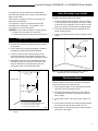
Product Features
Safety Device
This heater has a pilot with an Oxygen Depletion
Sensor shutt-off system (ODS). The ODS pilot is a
required feature for vent-free heaters. The ODS pilot
shuts off the heater if the normal air oxygen content is
reduced to 18%.
Piezo Ignition System
This heater has a piezo ignitor. This system requires no
matches, batteries or other sources to light the heater.
Models Type Min. Max. Setting Min. Max.
VERMONT
C
astings
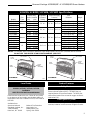
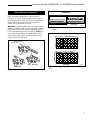
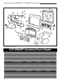
Gas Control
Front
Panel
Grille
Guard
Frame
Body
Assembly
VCBVMN/MP
3769
VERMONT
C
astings
Gas Control
Front
Panel
Grille
Guard
Frame
Body
Assembly
3772
Fig. 1 Product identification.
VCPVMN/MP

4
Vermont Castings VCBVMN/MP & VCPVMN/MP Room Heaters
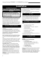
Installation
Installation Requirements
Fresh Air for Combustion and Ventilation
WARNING:
This heater must have fresh air for proper
operation. If not, poor fuel combustion could
result. Read the following instructions to insure
proper fresh air for this and other fuel-burning
appliances in your home.
Modern construction standards have resulted in homes
that are highly energy-efficient and that allow little heat
loss. Your home needs to breathe, however, and all
fuel-burning appliances need fresh air to function
properly and safely. Exhaust fans, clothes dryers,
fireplaces and other fuel burning appliances all use the
air inside the building. If the available fresh air supply is
insufficient to meet the demands of these appliances,
problems can result.
Provide for Adequate Ventilation
Any space within a home can be classified in these
categories:
Unusually tight construction: The air that leaks
around doors and windows may provide enough fresh
air for combustion and ventilation. However, in buildings
of unusually tight construction, you must provide
additional fresh air. Unusually tight construction is
defined as construction where:
Walls and ceilings exposed to the outside atmosphere
have a continuous water vapor retarder with a rating of
one perm or less with openings gasketed or sealed
and;
Caulking or sealants are applied to areas such as joints
around window and door frames, between sole plates
and floors, between wall/ceiling joints, between wall
panels, at penetrations for plumbing, electrical and gas
lines, and at other openings.
Unconfined space: An unconfined space whose
volume is not less than 50 cubic feet for each 1,000
Btu/Hr of the aggregate input rating of all appliances
installed in that space. Rooms communicating directly
with the space in which the appliances are installed,
through openings not furnished with doors are consid-
ered a part of the unconfined space.
Confined space: A confined space whose volume is
less than 50 cubic feet for each 1,000 Btu/Hr of the
aggregate input rating of all appliances in that space.
WARNING: You must provide additional ventilation air
in a confined space.
For proper operation of the unit, provide fresh air
opening(s) to the room. Follow the National Fuel Code
NFPA54/ANSI Z223.1, for required size of combustion
and ventilation openings.
NOTICE: A qualified service technician should install
heater. Follow all local codes.
Gas Type
Verify the type of gas supply to be used, either natural
gas or LP (Propane), and make sure the marking on the
appliance rating plate agrees with that of the supply
gas. The rating plate is located on the side of the
heater, which indicates the type of gas the heater is
orificed for.
Items Needed for Heater Installation
Before installing the heater, make sure you have these
items:
• Gas piping (check local codes)
• Test gauge connection
• Sealant (resistant to LP gases) - approved
thread compound
• Manual shut-off valve
*
• Sediment trap - where required
• Ground joint union
• Tee joint and pipe wrench
*
An installer supplied design-certified manual shut-off valve
with 1/8” NPT tap connection.
Locating the Heater
This heater is designed to be mounted on a wall or on
the floor.
WARNING: Never install the heater:
• in a bathroom
*
,
• in a recreational vehicle,
• where curtains, furniture, clothing or other
flammable objects are less than 36” from the
front, top, or sides of the heater,
• as a fireplace insert,
• in high traffic areas, or
• in windy or drafty areas.
*
Models VCPV06M(N,P) permitted for bathroom installations.
WARNING: Vent-free heaters add moisture to the air.
Although this is beneficial, installing heater in rooms
without enough ventilation may cause mildew formation
from too much moisture content. See National Fuel
Code for Fresh Air for Combustion and Ventilation.

5
Vermont Castings VCBVMN/MP & VCPVMN/MP Room Heaters
This appliance may be installed in an aftermarket*
manufactured (mobile) home, where not prohibited by
state or local codes.
*Aftermarket: Completion of sale, not for purpose of
resale from manufacturer.
This appliance is only for use with the type of gas
indicated on the rating plate. This appliance is not
convertible for use with other gases.
CAUTION: If you install the heater in a home garage:
• Heater must be at least 18” above floor
• Locate heater where moving vehicle will not hit it.
Attach Mounting Screws to Wall
NOTE: Wall anchors and mounting screws are in
hardware package provided with heater.
1. Install mounting screws on wall as shown in Figure
3. Use enclosed “paper template” for proper location
of holes. Be sure template is level. It may be neces-
sary to use plastic or lead anchors for plaster walls.
2. Drill holes at marked locations using 9/64” drill bit.
Insert mounting screw.
3. Leave screw head out from wall far enough to attach
heater.
Preparing for Installation
1. Remove heater from carton.
2. Remove all protective packaging applied to heater
for shipment.
3. Check heater for any shipping damage. If heater is
damaged, promptly inform dealer/distributor.
4. Select a location for the heater that will provide
maximum exposure of the radiant surface to the
room, but will not be subjected to accidental contact.
5. Adequate clearance must be available around the
air opening. Refer to Figure 2 for clearances that
must be maintained to the side walls, floor and
horizontal surface surrounding the heater.
Wall Anchor Method
When mounting heater to hollow walls (wall areas
between studs) or solid walls (concrete or masonry) it
may be necessary to use wall anchors.
1. Place paper template on wall maintaining minimum
clearance. Be sure template is level.
2. Drill holes at marked locations using 5/16” drill bit.
For solid walls, concrete or masonry, drill holes at
least 1” deep.
3. Insert plastic anchor. Tap anchor flush to wall. (Fig.
4)
4. Insert screw into wall anchor leaving screw head out
far enough from wall to attach heater. (Fig. 4)
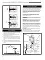
5. Hang heater on mounting screws in holes provided
at the rear of the heater.
13"
(330mm)
Min.
A
20"
(508mm)
Min.
A = 21¹⁄₄" (330 mm) @ 30,000 Btu/ hr Model
13¹¹⁄₁₆" (347 mm) @ 18,000/20,000 Btu/ hr Model
9⁷⁄₈" (251 mm) @ 10,000 Btu/ hr Model
9⁷⁄₈" (251 mm) @ 6,000 Btu/ hr Model
36"
(914mm)
Min.
Ceiling
Adjacent Wall
Screw Holes
RH100
Fig. 2 Minimum clearances to floor, adjacent walls and
ceiling.
Mounting Screws
RH101
Fig. 3 Use paper template supplied to mark location of
mounting holes. Be sure template is level.
Template

6
Vermont Castings VCBVMN/MP & VCPVMN/MP Room Heaters
1/16"
(1.6mm)
RH102
Fig. 4 Wall anchor.
Connect to Gas Supply
Before connecting the appliance, turn off all gas appli-
ances. Close the main gas valve at the gas meter or Lp
tank. Make certain there is good ventilation where the
installation will be made. Installation should comply with
all applicable building codes and ANSI Z223.1, latest
edition. Use LP gas resistant pipe compound to seal
threaded joints.
An installer supplied, design certified gas pressure
regulator must be installed to bring the gas supply
pressure down to 14” w.c.
WARNING: Never connect an unregulated gas line
to the heater.
IMPORTANT: Check gas line pressure before connect-
ing heater to gas line. Gas line pressure must not be
higher than 14” w.c. If gas line pressure is higher,
heater gas pressure regulator damage could occur.
NOTE: The gas line connection can be made with 3/8”
black or steel pipe. Internally tinned copper tubing may
be used in certain areas. Check your local codes. Use
pipe of large enough diameter to allow proper gas
volume to heater. If pipe is too small, undue pressure
loss will occur.
CAUTION: Use pipe joint sealant that is resistant to
liquefied petroleum gases.
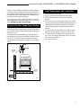
Install sediment trap in supply line as shown in Figure
6. Locate sediment trap where it is within reach for
Pressure
Regulator
3/8” NPT Nipple
Tee Joint
Reducer
Bushing to
1/8” NPT
1/8” NPT
Plug Tab
Heater
Cabinet
Ground Joint
Union
Manual
Shutt-Off
Valve
From Gas
Meter
Test Gauge
Connection
Tee Joint
Pipe Nipple
Cap
Sediment
Trap
Natural Gas
(4” w.c. to
10.5” w.c. Pressure)
LP Gases
(11.5” w.c. to
14.0” w.c. Pressure)
RH103
Fig. 6 Gas line connection.
Floor Installation
1. Heater may only be installed on a noncombustible
flat surface. Wall mounting screws may be used to
keep heater from side movements.
2. Measure heater mounting screw location “X” as
desired above floor. (Fig. 5)
3. Use enclosed “paper template” for proper distance
between holes. Be sure template is level. It may be
necessary to use plastic or lead anchors for plaster
wall.
4. Drill holes at marked locations using 9/64” drill bit.
5. Leave screw head out from wall far enough to attach
heater.
X
Screw Holes
Floor
RH107
Fig. 5 Optional wall mounting screws for floor installation.

7
Vermont Castings VCBVMN/MP & VCPVMN/MP Room Heaters
cleaning. Locate sediment trap where trapped matter is
not likely to freeze. A sediment trap prevents moisture
and contaminants from going into the heater controls. If
the sediment trap is not installed or is installed wrong,
the heater may not operate properly.
Test for gas leaks with a mild soap and water solution.
Apply water/soap solution with brush only -
do not over
apply. NEVER test with an open flame.
Pressure Test Gas Supply Piping System
The appliance and its individual shut-off valve must be
disconnected from the gas supply piping system during
any pressure testing of the system at test pressures in
excess of 1/2 psi.
The appliance must be isolated from the gas supply
piping system by closing the individual manual shut-off
valve (Fig. 7) during any pressure testing of the gas
supply system at test pressures equal to or less than
1/2 psi.
Open
Closed
Manual
Shut-Off
Valve
Manual
Shut-Off
Valve
Control Valve
RH104
Fig. 7 Manual shut-off valve location.
Leak Testing Heater Gas Connections
1. Open manual shut-off valve.
2. Open main gas valve located near gas meter.
3. Make sure control knob of heater is in the OFF
position.
4. Check all joints from manual gas valve up to control
valve and including the manifold assembly. Apply the
soap solution around the connections, valve and
tubing. Soap bubbles will appear where a leak is
present.
5. If a leak is present, immediately turn off gas supply,
tighten any leaky fittings, turn gas on and recheck.
6. To check burner and safety valve, the burner must
be lit. (See Operating Instructions) Check the rest of
the connections for leaks.
7. Turn off the heater.

8
Vermont Castings VCBVMN/MP & VCPVMN/MP Room Heaters
Operating Instructions
FOR YOUR SAFETY - READ THIS SECTION
BEFORE LIGHTING
WARNING: IF YOU DO NOT FOLLOW THESE
INSTRUCTIONS EXACTLY, A FIRE OR EXPLO-
SION MAY RESULT CAUSING PROPERTY DAM-
AGE, PERSONAL INJURY OR LOSS OF LIFE.
A. BEFORE LIGHTING smell all around the appliance
area for gas. Be sure to smell next to floor because
some gas is heavier than air and will settle on the
floor.
IF YOU SMELL GAS:
1. Do not try to light any appliance.
2. Do not touch electrical switches; do not use any
phone in your building.
3. Immediately call your gas supplier from a
neighbor’s phone. Follow your gas supplier’s
instructions.
4. If you cannot reach your gas supplier, call the fire
department.
B. Use only your hand to push in or turn the gas valve
control knob. Never use tools. If the knob will not
push in or turn by hand, do not try to repair it, call a
qualified service technician. Force or attempted
repair may result in a fire or explosion.
C. Do not use this appliance if any part has been under
water. Immediately call a qualified service technician
to inspect the appliance and to replace any part of
this control system and any gas control which has
been under water.
Lighting Instructions
1. Read the safety information on previous page.
2. Make sure manual shut-off valve is fully open.
3. Push in gas control knob slightly and turn clockwise
to the OFF position.
4. WAIT 5 MINUTES TO CLEAR OUT ANY GAS. If
you then smell gas, STOP! Follow A in the safety
information. If you do not smell gas, go to next step.
5. Push in gas control knob slightly and turn counter-
clockwise to ‘PILOT/IGN” and depress for five
(5) seconds. This will allow air to bleed from the gas
system.
6. Release control knob pressure and turn clockwise
to “OFF”.
7. Depress control knob while OFF, then turn back to
PILOT/IGN. This should cause the spark from the
piezo ignitor to light the pilot gas. Keep control knob
depressed for ten (10) seconds before releasing. If
pilot does not light, repeat steps 5 – 7, or use a match.
8. To select the heating level desired, partially press
down the control slightly and rotate counterclockwise
. Release the downward pressure on the knob
while continuing to turn until the knob locks at the
desired setting position. Do not operate between the
locked positions.
To Turn Off Gas To Heater
Turning Heater Off
Turn control knob clockwise to the OFF position.
Turning Burner Only Off (Pilot stays lit)
Turn control knob clockwise to the PILOT position.
CAUTION: Do not try to adjust heating levels by
using the manual shut-off valve.
NOTE: The thermostat sensing bulb measures the
temperature of air near the heater cabinet. This may not
always agree with room temperature (depending on
housing construction, installation location, room size,
etc.). Frequent use of your heater will let you determine
your own comfort levels.
Manual Lighting Instructions
1. Remove lower front panel.
2. Follow steps 1 through 4 as stated under Lighting
Instructions.
3. Press and turn control knob counterclockwise
to the PILOT/IGN position.
4. With control knob pressed in, strike match, hold
match to pilot until pilot lights.
5. Keep control knob pressed in for 30 seconds after
lighting pilot. After 30 seconds, release control knob.
6. Replace lower front panel.
OFF
PILOT/IGN
LOW
MED
HIGH
OFF
PILOT/IGN
HIGH
LOW
RH105
Fig. 8 Control knob.
VCBV10 & VCPV10 Only

9
Vermont Castings VCBVMN/MP & VCPVMN/MP Room Heaters
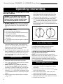
Pilot and Burner Inspection
Each time you light your heater check that the pilot
flame and burner flame patterns are as shown in
Figures 9, 10 and 11. If flame patterns are incorrect,
turn the heater off. Contact your dealer or a qualified
gas technician for assistance. Do not operate the
heater until the pilot flame is correct.
WARNING: If yellow tipping occurs, your heater could
produce increased levels of carbon monoxide. If burner
flame pattern shows yellow tipping, follow instructions
in the Troubleshooting section on page 10. NOTE: Do
not mistake orange flames with yellow tipping. Dirt or
other particles may enter the heater and cause tran-
sient patches of orange flame.
VCPV Heater
Correct
Incorrect
RH109
Fig. 11 Correct burner flame pattern for the VCPV plaque
heater.
Ignitor Electrode
Thermocouple
Correct
Incorrect
Fig. 9 Proper pilot flame.
P103
Yellow Tipping
Correct
Incorrect
RH106
Fig. 10 Correct burner flame pattern for the VCBV blue flame
burner.
VCBV Heater

10
Vermont Castings VCBVMN/MP & VCPVMN/MP Room Heaters
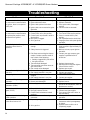
Problem
When control knob is pressed
in and turned counterclockwise
to ignition, there is no spark at
ODS pilot.
When control knob is pressed
in and turned counterclockwise
to ignition/pilot position, there
is spark but no ignition.
ODS pilot lights but flame goes
out when control knob is
released.
Burner does not light after ODS
Possible Cause
1. Ignitor electrode positioned wrong.
2. Ignitor electrode broken.
3. Ignitor cable pinched or broken.
4. Ignitor cable not connected to ignitor
electrode.
1. Gas supply turned off.
2. Control knob not in pilot position.
3. Control knob not pressed in while in
pilot position.
4. ODS pilot is clogged.
5. Air in gas lines.
1. Control knob not pressed long
enough.
2. Safety interlock is triggered.
3. Pilot flame not touching the thermo-
couple. Problem could be result of
one or both of the following:
• Partially clogged ODS pilot orifice.
• Low gas pressure.
4. Thermocouple damaged.
5. Thermocouple connection loose at
gas control valve.
6. Gas control valve damaged.
1. Burner orifice clogged.
2. Gas supply pressure is very low.
1. Main burner carry over ports
clogged.
2. Gas supply pressure is very low.
1. Burner orifice is clogged.
2. Burner ports damaged.
1. Not enough air.
1. Plaque(s) is damaged.
2. Inlet gas pressure too low.
3. Control knob set between locked
positions.
1. Residues from manufacturing
processes.
1. Air passageways blocked.
2. Air in gas line.
What To Do
1. Replace ignitor electrode.
2. Replace electrode.
3. Free ignitor cable, if damaged
replace.
4. Connect cable to electrode.
1. Turn gas supply on.
2. Turn control knob to pilot position.
3. Press in control while in pilot
position.
4. Call a qualified service technician.
5. Purge gas lines and repeat ignition
operation.
1. After ODS pilot lights, keep control
knob pressed in approximately 30
seconds.
2. Wait one minute, repeat ignition
operation.
3. Contact your gas company, gas
supplier or qualified service
technician.
4. Replace thermocouple.
5. Hand tight until snug then tighten
1/4 turn with a wrench.
6. Replace gas control.
1. Clean burner orifice.
2. Contact gas supplier.
1. Clean main burner ports.
2. Contact gas supplier.
1. Clean burner orifice.
2. Replace burner.
1. Check air passageways and
burner for dirt and debris (Refer to
Maintenance section)
1. Replace burner.
2. Contact local gas supplier.
3. Turn control knob until it locks at
desired setting.
1. Will stop after a few hours of
operation.
1. Check minimum installation
clearances and air passageways
for debris.
2. Operate burner until the air is
completely purged.
pilot is lit.
Delayed ignition.
Burner backfiring during
operation.
Yellow flames during burner
operation. (VCBV)
Burner plaque(s) does not
glow. (VCPV)
Slight smoke and odor during
initial operation.
Heater produces a whistling
noise when burner is lit.
Troubleshooting

11
Vermont Castings VCBVMN/MP & VCPVMN/MP Room Heaters
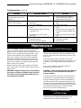
Troubleshooting,
continued
Problem Possible Cause Solution
Heater produces a clicking
noise just after burner is lit or
turned off.
Gas odor even when control
knob is in OFF position.
Gas odor during combustion.
Heater shuts off on ODS
1. Metal expanding and contracting.
1. Gas leaks. Refer to front page
Warnings.
2. Gas control defective.
1. Foreign matter in gas or on burner
ports.
2. Heater burning vapors form paint,
impurities in air.
3. Gas leaks, refer to front page
Warnings.
1. Not enough fresh air is available.
2. Low gas pressure.
3. ODS pilot partially clogged.
1. This is common with heaters. If
noise is excessive, contact a
qualified service technician.
1. Locate and correct leaks immedi-
ately.
2. Replace gas control.
1. Check gas passage way and
burner.
2. Ventilate room, stop storing and
using odor causing products near
heater.
3. Locate and correct leaks immedi-
ately.
1. Open window.
2. Contact gas supplier.
3. Clean the pilot.
Maintenance
Dust, lint, cobwebs or debris may affect heater perfor-
mance. The heater draws air into it during normal
operation and in the process dust, lint or debris may be
drawn in also. It is important to keep the burner , gas
control and combustion and circulating air passage-
ways clean. Inspect or have these areas inspected
annually at the beginning of the heating season by a
qualified service person. Depending on the surround-
ings, the room heater may require frequent cleaning
due to excessive lint or debris.
Before cleaning ensure the gas supply is off and the
gas control knob is in the OFF position. Make sure the
heater is cool.
WARNING: Danger of bodily injury. If fan assembly
accessory is used, turn off power supply at discon-
nect switch or service panel before removing any
access panels from heater.
Burner and ODS Pilot Cleaning
Clean the exterior with soft bristle brush, vacuum
cleaner or pressurized air. Never use a wooden tooth-
pick as it may break off and clog the ODS pilot or main
burner port.
Use a flashlight to inspect the main burner inlet to
ensure it is not blocked. If obstruction can be seen, use
a metal wire coat hanger that has been straightened
out.
Use a vacuum cleaner to clean the primary air
openings to the main burner(s).
WARNING: Failure to keep the primary air openings
to the burner(s) clean may result in sooting and
property damage.
In order to clean ODS pilot orifice, use pressurized air
to blow dust out. Sometimes blowing air backwards
through the pilot will get rid of the accumulated dirt. If
that does not work, blow out any dust through primary
air openings of pilot assemblies (Daemyeong has two
openings; one beneath the bimetal strip and the second
one opposite from bimetal strip. Use the one wide
open, do not try to lift the bimetal strip.)
Cleaning Air Passageways
and Unit Casings
Use a vacuum cleaner or pressurized air to clean the
combustion and circulating air passageways and
dampened cloth to clean the cabinet/casing.

12
Vermont Castings VCBVMN/MP & VCPVMN/MP Room Heaters
11
13
14
15
10a,b
9
7
8a,b
5
2
3
1
4
16
16
17
19a
21
18
20
22
23
24
19b
12a,b
6a,b
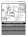
The Vermont Castings Majestic Products Company reserves the right to make changes in design, materials, specifications, prices and discontinue
colors and products at any time, without notice.
3769
VCBVMN/MP Unvented Room Heater
Item / Model Number VCBV10MN/MP VCBV20MN/MP VCBV30MN/MP
1. Guard Assembly RBW33XX0 RBW30XX0 RBW26XX0
2. Glass Panel RBC02XC0 RBC02XB0 RBC02XA0
3. Holder Glass RBP63PC0 RBP63PB0 RBP63XPA0
4. Reflector RBP71PX0 RBP70PX0 RBW23XX0
5. Cover Heat - Upper -- RBP61XB0 RBP61XA0
6a. Pressure Regulator (Daemyeong Korea) - Natural DR40M2PN DR40M2KN DR40M3KN
6b. Pressure Regulator (Daemyeong Korea) - LP DR40M2PL DR40M2KL DR40M3KL
7. Nozzle Holder RBM06XX0 RBM06XX0 RBM06XX0
8a. ODS Pilot Assembly (Daemyeong Korea) - Natural DS98N02 DS98N02 DS98N02
8b. ODS Pilot Assembly (Daemyeong Korea) - LP DS98PL02 DS98PL02 DS98PL02
9. Fix Nut - Nozzle Holder RBM08XX0 RBM08XX0 RBM08XX0
10a. Main Nozzle - Natural RBM07XE RBM07XA RBM07XC
10b. Main Nozzle - LP RBM07F0 RBM07B0 RBM07E0
11. Bracket - Valve RBP59XX0 RBP59XX0 RBP59XX0
12a. Gas Control (Daemyeong Korea) - Natural DMV101PA DMV100PA DMV100PC
12b. Gas Control (Daemyeong Korea) - LP DMV101PB DMV100PB DMV100PD
13. Tubing Outlet Assembly RBT28XX0 RBT22XX0 RBT16XX0

13
Vermont Castings VCBVMN/MP & VCPVMN/MP Room Heaters
14. Tubing ODS Assembly RBT27XX0 RBT21XX0 RBT15XX0
15. Tubing Inlet Assembly RBT26XX0 RBT20XX0 RBT14XX0
16. Leg - Front RBI06XX0 RBI06XX0 RBI06XX0
17. Front Panel RBP69PA0 RBP66PA0 RBW22XA0
18. Burner Assembly RBW13XX0 RBW09XX0 RBW08XX0
19a. Burner Support - Left RBP06XA RBP06XA- RBP06XA
19b. Burner Support - Right RBP06XB0 RBP06B0 RBP06B0
20. Frame Body Assembly RBW31PB0 RBW31PB0 RBW20PB0
21. Leg - Rear RB105XX0 RB105XX0 RB108XX0
22. Knob - Valve RB104XX0 RB104XX0 RBI04XX0
23. Shield RBP100 RBP101 RBP105
24. Rear Radiant Shield -- 10003986 10003984
VCBVMN/MP,
continued
Item / Model Number VCBV10MN/MP VCBV20MN/MP VCBV30MN/MP

14
Vermont Castings VCBVMN/MP & VCPVMN/MP Room Heaters
Vermont Castings, Majestic Products reserves the right to make changes in design, materials, specifications, prices and discontinue colors and
products at any time, without notice.
VCPVMN/MP Unvented Room Heater
Item / Model Number VCPV06MN/MP VCPV10MN/MP VCPV18MN/MP VCPV30MN/MP
1. Cover Heat - Lower RCP10XC0 RCP10XC0 RCP10XB0 RCP10XA0
2. Guard Assembly RBM33XX0 RBW33XX0 RBW30XX0 RBW26XX0
3. Reflector 0RH0002 RCP34PX0 RCP33PX0 RCW10XX0
4. Cover Heat - Upper -- - RBP61XA0 RBP61XA0
5. Leg Front RB106XX0 RBI06XX0 RBI06XX0 RBI06XX0
6. Front Panel RBP69PA0 RBP69PA0 RBP66PA0 RBP57PA0
7. Burner Body Assembly 2RH0006 RCW13XX0 RCW12XX0 RCW11XX0
8. Ceramic Plate 3D0310 RCC03XX0 RCC01XA0 RCC01XA0
9. Frame Body Assembly RBW32PB0 RBW32PB0 RBW27PB0 RBW20PB0
10. Knob - Valve RB104XX0 RBI04XX0 RBI04XX0 RBI04XX0
11. Leg - Rear RB105XX0 RBI05XX0 RBI05XX0 RBI05XX0
12. Link - Valve RCP13XE0 RCP13XE0 RCP13XD0 RCP13XC0
13. Fix Pin - Link RCS01XX0 RCS01XX0 RCS01XX0 RSC01XX0
14a. Gas Control (Daemyeong Korea) DMV100PHB DMV200PA DMV300PA DMV300PA
15. Tubing Inlet Assembly RCT65XX0 RCT65XX0 RCT51XX0 RCT37XX0
16. Tubing Outlet - A Assembly 3RH0005 RCT66XX0 RCT52XX0 RCT38XX0
17. Tubing Outlet - B Assembly -- RCT67XX0 RCT53XX0 RCT09XX0
18. Tubing Outlet - BL Assembly -- -- -- RCT40XX0
19. Tubing Outlet - BR Assembly -- -- -- RCT41XX0
7
4
2
3
1
5
5
11
9
6
8
10
12
13
14
17
15
26
18
23
28a,b
27
19
22
20
21
16
24
25a,b
30
29
3769

15
Vermont Castings VCBVMN/MP & VCPVMN/MP Room Heaters
VCPVMN/MP,
continued
Item / Model Number VCPV06MN/MP VCPV10MN/MP VCPV18MN/MP VCPV30MN/MP
20. Tubing Outlet - C Assembly -- -- RCT54XX0 RCT12XX0
21. Tubing Outlet - CL Assembly -- -- -- RCT13XX0
22. Tubing Outlet - CR Assembly -- -- RCT14XX0 --
23. Manifold - “C” -- -- RCD02XX0 --
24. Tubing ODS Assembly RCT63XX0 RCT63XX0 RCT59 RCT45
25a. ODS Pilot Assembly
(Daemyeong Korea) - Natural DS99PN03 DS98PN01 DS98PN01 DS98PN01
25b. ODS Pilot Assembly
(Daemyeong Korea) - LP DS98PL01B DS98PL01 DS98PL01 DS98PL01
26a. Main Nozzle - Natural RCM02XG0 RCM02XD0 RCM02XB0 RCM02XA0
26b. Main Nozzle - LP RCM02XB0 RCM02XE0 RCM02XC0 RCM02XB0
27. Connector - “B” RCM01XX0 RCM01XX0 RCM01XX0 RCM01XX0
28a. Pressure Regulator
(Daemyeong Korea) - Natural
DR40M3PN
DR40M2PN DR40M3PN DR40M5PN
28b. Pressure Regulator
(Daemyeong Korea) - LP
DR40M3PL
DR40M2PL DR40M3PL DR40M5PL
29. Rear Radiant Heat Shield -- -- 10003986 10003985
30. Shield RBP84 RBP84 RBP101 RBP104
Accessories
Contact Vermont Castings Majestic, Products with
questions concerning prices and policies covering
replacement parts. Parts may be ordered through you
Vermont Castings distributor or dealer.
You will need the following information when ordering
replacemet parts:
• the appliance model number,
• the serial number, and
• a description of the part.
Should you need additional information beyond
what your dealer can furnish, contact:
Vermont Castings, Majestic Products
410 Admiral Blvd.
Mississauga, Ontario
Canada L5T 2N6
Telephone: 905-670-7777
The following accessories are available from your local Vermont Castings dealer. Each accessory comes with a
separate installation instruction. Be sure to read each instruction thoroughly before installing.
Description Model Number
Manual Fan Kit FMA-F
Thermostat Fan Kit FMA-FT
Model and serial numbers are listed on the rating
plate (located on right side of heater). Record your
model and serial numbers here for future reference.
Model # ___________________________________
Serial # ___________________________________

16
Vermont Castings VCBVMN/MP & VCPVMN/MP Room Heaters
© Vermont Castings, Majestic Products
Warranty
Service and Limited Warranty
The Vermont Castings Majestic Products Company
warrants this product to be free form defects in materi-
als and components for two (2) years from the date of
first purchase, provided that the product has been
properly installed, operated and maintained in accor-
dance with all applicable instructions. To make a claim
under this warranty the Bill of Sale or cancelled check
must be presented.
This warranty is extended only to the original retail
purchaser. This warranty covers the cost of part(s)
required to restore this heater to proper operating
condition and an allowance for labor when provided by
a Vermont Castings authorized dealer/distributor.
Warranty part(s) MUST be obtained through authorized
dealers of this product and/or Vermont Castings Majes-
tic Products who will provide original factory replace-
ment parts. Failure to use original factory replacement
parts voids this warranty. The heater MUST be installed
by a qualified installer in accordance with all local
codes and instructions furnished with the unit.
This warranty does not apply to parts that are not in
original condition because of normal wear and tear, or
parts that fail or become damaged as a result of
misuse, accidents, lack of proper maintenance or
defects caused by improper installation. Travel, diag-
nostic cost, labor, transportation and any and all such
other costs related to repairing defective heater will be
the responsibility of the owner.
TO THE FULL EXTENT ALLOWED BY THE LAW OF
THE JURISDICTION THAT GOVERNS THE SALE OF
THE PRODUCT; THIS EXPRESS WARRANTY EX-
CLUDES ANY AND ALL OTHER EXPRESSED WAR-
RANTIES AND LIMITS THE DURATION OF ANY AND
ALL IMPLIED WARRANTIES, INCLUDING WARRAN-
TIES OF MERCHANTABILITY AND FITNESS FOR A
PARTICULAR PURPOSE TO TWO (2) YEARS FROM
THE DATE OF FIRST PURCHASE; AND THE VER-
MONT CASTINGS MAJESTIC PRODUCTS COMPANY
SHALL NOT BE LIABLE FOR ANY OTHER DAMAGES
WHATSOEVER INCLUDING INDIRECT, INCIDENTAL
OR CONSEQUENTIAL DAMAGES.
Some states do not allow a limitation on how long an
implied warranty lasts or an exclusion or limitation of
incidental or consequential damages, so the above
limitation on implied warranties, or exclusion or limita-
tion on damages may not apply to you.
This warranty gives you specific legal rights, and you
may also have other rights that vary from state to state.
Always specify model and serial number when commu-
nicating with the factory.
Vermont Castings, Majestic Products
410 Admiral Blvd. • Mississauga, Ontario • Canada, L5T 2N6 • 905-670-7777
www.majesticproducts.com • www.vermontcastings.com
-
 1
1
-
 2
2
-
 3
3
-
 4
4
-
 5
5
-
 6
6
-
 7
7
-
 8
8
-
 9
9
-
 10
10
-
 11
11
-
 12
12
-
 13
13
-
 14
14
-
 15
15
-
 16
16


Vermont Casting VCBV20 User manual
- Category
- Fireplaces
- Type
- User manual
Ask a question and I''ll find the answer in the document
Finding information in a document is now easier with AI
Related papers
-
Vermont Castings VCBV10TN User manual
-
Vermont Casting 3031 User manual
-
-
-
-
Vermont Castings 3370 User manual
-
-
Other documents
-
-
MONESSEN Natural Blaze See-Thru Vent Free Gas Log Set Owner's manual
-
Vermont Castings 3370 User manual
-
Majestic fireplaces UV36RP Operating instructions
-
-
-
World Marketing of America KW(N307,P308) User manual
-
Vermont Castings VL24RP Operating instructions
-
 ProCom Heating MN100TBG User manual
-
