Page is loading ...

© 2016
P
Sheet# 4
IMPORT
A
Read ca
r
by a qu
a
directio
n
addition
a
factory
d
uncertai
n
manufa
c
This lu
m
with th
e
ELECTRI
C
injury,d
e
fire.LE
D
only.
Do not i
Notfor
u
Ungrou
n
transien
t
equipm
e
VOIDTH
GENERA
Upon re
c
brought
packagi
n
The war
Compar
e
thelabe
material
These L
E
applicati
40°Cam
P
hilips Lighting Holdi
n
43561064920
A
NT:
r
efully before
a
lified Electri
c
n
s to cover
e
a
l informatio
n
d
irectly for as
s
n
ty.Imprope
c
turer’swarra
n
m
inaire must
b
e
se instructio
C
CODE.Fail
u
e
athand/orp
r
D
luminaires
s
nstall in boxe
d
u
seinrecesse
d
n
ded power
t
voltageswhi
c
e
nt.Useofth
EWARRANTY.
L:
c
eipt, inspect
to the atte
n
n
ghasbeente
ranty does no
e
the catalog
d
lon thecarto
n
.
E
D wall scon
c
ons and ETL/
C
bient.
n
g B.V. All rights rese
revision D
installing. All
c
ian. These in
s
e
very variati
o
n
, consult yo
s
istance befor
r installation
a
n
ty.
b
e installed a
n
ns, all local
u
retodosom
a
r
opertyloss/d
a
hould be ope
d
‐in areas or
a
d
applications
distribution
c
hcan cause
f
isequipment
o
for any freigh
n
tion of the
stedandappr
t apply to da
m
d
escription lis
t
n
toassure yo
c
e luminaires
C
ETL listed fo
r
Directmou
n
r
ved.
work should
s
tructions ma
y
o
n and detail
ur vendor o
r
e attempting
a
nd/or utiliza
t
n
d grounded
i
codes and t
h
a
yresultinse
r
a
magefromel
e
r
ated on grou
a
reas that ma
y
systems ma
y
f
ailureofany
t
o
nungrounde
t damage, w
h
delivering ca
ovedfordeliv
e
m
age caused
b
t
ed on the pa
c
uhave receiv
e
are intende
d
r
wet locatio
n
n
ting
AER
O
Revi
s
b
e performed
y
not provide
.To obtain
r
contact the
anything with
t
ion may void
i
n accordance
h
e NATIONAL
r
iouspersonal
e
ctrocutionor
nded systems
y
entrap heat.
y
carry high
t
ypeelectrical
dsystemswill
h
ich should be
rrier. Factory
e
rybycarrier.
b
y the carrier.
c
king slip with
e
dthecorrect
d
for outdoor
n
s and‐30 to
O
SCAPE
s
ed 1/7/2015
LED
W
LAR
G
SM
A
W
ALL
S
G
EASW
A
A
LLASW
A
Indirectm
o
S
CONCE
A
SSEMB
L
A
SSEMB
o
unting
Page 1 o
f
L
Y
LY
f
6

© 2016
P
Sheet# 4
P
hilips Lighting Holdi
n
43561064920
n
g B.V. All rights rese
revision D
r
ved.
AER
O
Revi
s
O
SCAPE
s
ed 1/7/2015
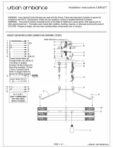
1.
2.
3.
4.
5.
LED
W
MOU
N
‐
M
Remove th
e
With gaske
t
b
racket usi
n
anchors, us
e
Apply silic
wall mount
PLACE C
A
Liftfixture
u
keyholeslo
t
nowhangf
r
wiring.
Reference
s
sectionfor
f
inaccordan
ordinances,
Code.
Oncewirin
g
footholdin
t
mountingb
mountbra
c
W
ALL
S
N
TINGIN
S
M
OUNTING
A
e
wall mount b
r
t
facing the w
a
n
g appropriate
e
integral bub
b
one caulking i
n
bracket on to
p
A
ULK ON BO
T
u
pandinsert
e
t
inthewallm
r
eelyallowing
s
tandardwirin
g
f
ixturewiring
S
cewithallele
c
aswellasthe
g
iscomplete,
l
t
owallmount
oltensuringa
l
c
ket.
S
CONCE
S
TRUCTI
O
A
SSEMBLY‐
r
acket from it
s
a
ll, loosely atta
anchors. Befo
r
b
le level to lev
e
n
seams betw
e
p
and both side
T
TOM SEAM
e
ndof“Hands
ountbracket.
T
youtousebo
t
g
undertheW
S
eeFigure1
.
c
tricalandsaf
e
mostrecent
N
l
iftluminairea
bracket.Tiltfi
x
l
lwiresaretu
c
Page 2 o
f
O
NS
s
packaging.
ch wall mount
r
e tightining
e
l box.
e
en wall and th
s. DO NOT
.
Free”cablein
t
T
hefixturewil
t
hhandsfor
iringInstructi
o
Wireluminair
e
e
tycodesand
N
ationalElectr
ndlocate
x
turetowards
c
kedinsidewa
l
f
6
e
t
o
l
o
n
e
i
c
l

© 2016
P
Sheet# 4
WARNI
N
WITHA
C
VERIFY
T
ONTHE
‘UNV’
O
WILL O
P
GROUN
D
PROPER
T
LUMINA
CONNE
C
P
hilips Lighting Holdi
n
43561064920
WIRI
N
N
G: WIRING S
H
C
CEPTEDNEC
P
T
HAT THE SU
P
LUMINAIRE
N
O
R ‘‐8’ VOLT
A
P
ERATE ON 1
2
D
INGISREQU
I
T
Y
S
AFETY.
C
IRE GROUN
D
C
TOR.
n
g B.V. All rights rese
revision D
N
G INST
R
H
OULD BE PE
R
P
RACTICE
S
B
Y
P
PLY VOLTA
G
N
AMEPLATE.L
U
A
GE CODE AR
20
‐277 VAC
S
I
REDTOINSU
R
C
ONNECT THE
D
LEAD T
O
r
ved.
R
UCTION
S
R
FORMED IN
A
Y
AQUALIFIED
G
E MATCHES
T
U
MINAIREPR
O
E
VOLTAGE
S
S
UPPLY VOLT
A
R
EPERSONAL
,
GREEN OR
B
O
A SUITAB
L
AER
O
Revi
s
S
A
CCORDANCE
ELECTRICIAN.
T
HAT SHOWN
O
VIDEDWITH
S
ENSING AND
A
GE. PROPER
PUBLIC,
A
ND
B
ARE COPPER
L
E GROUND
O
SCAPE
s
ed 1/7/2015
6.
Lumin
a
witha
also a
n
syste
m
SUPP
L
option
to co
n
willpr
o
anyot
LED
W
Holding fix
t
down.Torq
‐
a
ire will com
e
nadditional2
n
additional 2
m
(optional).
M
L
Y WIRE). Re
f
n
alvioletand
g
n
trol device. I
n
o
videconstan
t
herunusedle
a
W
ALL
S
t
ure in place
uemounting
s
STANDARD
e
with 3 flyin
g
leadsfordim
m
leads for 12
0
M
ake all suppl
y
f
er to lightin
g
g
ray0‐10VDC
d
n
dividually ca
p
t
100%power
a
ds.
Figure1
S
CONCE
tighten mou
s
crewsto50‐5
5
WIRING‐
g
leads for su
p
m
ingoperatio
n
0
V emergency
y
connections
g
plans to d
e
d
imminglead
s
p
ping off viole
t
operation.In
d
Page 3 o
f
nting set scr
e
5
in‐lb.
p
ply connectio
n
(optional),a
n
battery back‐
u
(USE MIN 9
0
e
termine if t
h
s
aretobewir
e
t
and gray lea
d
ividuallycap
o
f
6
e
w
ns
n
d
u
p
°C
h
e
e
d
d
s
o
ff

© 2016 Philips Lighting Holding B.V. All rights reserved. AEROSCAPELEDWALLSCONCE
Sheet# 443561064920 revision D Revised 1/7/2015 Page 4 of 6
CLEANINGANDMAINTENANCE
CAUTION: Never perform maintenance while luminaire is
energized or still hot from operation as this could result in
electrocution,injuryordeath.
Yourluminaireisdesignedforyearsoftrouble‐freeoperation.It
will occasionally be necessary to clean the lens assembly to
maintain optimal light level. The frequency of cleaning
will
depend on the ambientdirtlevel. The lens assembly should be
cleaned with any suitable non‐abrasive cleaning solution, soap
ordetergentandrinsedwithcleanwater.
ThesuppliedLEDdriveristhermallyprotected.Ifnecessary,the
luminaire will dim and/or shut down if temperature limit is
exceeded. If
the luminaire shuts off, determine the cause,
correctthecondition,andcyclepowertorestoreoutput.
ShouldyourequireanewLEDboard,duetooutagescoveredby
warranty, please contact the vendor for a replacement LED
board.
Should you require a new driver, please refer to the driver
replacementinstructionsbelow.
CAUTION:Itisstronglyrecommendedthatmounting/fastening
meansbe checked and retorqued,andthatthe integrityof all
electrical connections be verified at regular intervals such as
whenperformingroutinemaintenance,cleaning,etc.
‐DRIVERREPLACEMENT‐
If you determine that your luminaire outage is due to a non‐
operational LED driver, you will need to replace the LED driver
withadriverapprovedbyPhilipsengineering.Foranewdriver,
contact your vendorfor a replacement and following the steps
below:
CAUTION:TheseareHIGHVOLTAGE
driversandshouldonlybe
serviced by a qualified electrician. Make sure to DISCONNECT
THE LUMINAIREFROM POWER AND ALLOWTOCOOL BEFORE
SERVICING. Failure to do so can result in electrocution, injury
ordeath.
Figure2
1. Remove the (4) door retaining screws that secure the
doorassemblytothemainhousing.SeeFigure2
Figure3a
HINGE

© 2016 Philips Lighting Holding B.V. All rights reserved. AEROSCAPELEDWALLSCONCE
Sheet# 443561064920 revision D Revised 1/7/2015 Page 5 of 6
2. Allowdoortoslidedownonhinge,thenswingtoopen.
SeeFigure3a
3. DisconnectallofthewiresconnectedtotheLEDdriver.
Figure3b
4. To remove the driver door assembly, pinch the driver
doorhingetogethertounlockfrom hingebracket.See
Figure3b
5. Removethefour(4)screws holding the driver bracket
to release the driver, from the lens frame. See Figure
4aandFigure4b
Figure4a
Figure4b
6. Remove the thermal interface material off of the old
driver,fromthetopandbottom.
7. ReplacetheoldLEDdriverthermalinterfacematerialto
newdriver,fromthetopandbottom.
8. Place the LED driver and Bracket back onto the driver
doorandsecurethebracketscrews
inplace.
9. ReconnectLEDdriver(SeeFigure1)totheluminaire.
10. Replacethedriverdoorassemblyandre‐tightenthe(4)
doorretainingscrews.Torqueto28‐36in‐lb,seeFig2.
11. Reconnecttheluminairetopower.
DRIVER BRACKET
THERMAL INTERFACE
DRIVER
DRIVER SCREW(S)

© 2016 Philips Lighting Holding B.V. All rights reserved. AEROSCAPELEDWALLSCONCE
Sheet# 443561064920 revision D Revised 1/7/2015 Page 6 of 6
IMPORTANTSAFEGUARDSFOREBBOPTION
Whenusingelectricalequipment,basicsafetyprecautionsshouldalwaysbefollowed,includingthefollowing:
READANDFOLLOWALLSAFETYINSTRUCTIONS
1. TheASW‐EBBusesaseparateLEDarrayforemergencymode.Duringemergencymode,onlythisLEDwillbe
illuminated.
2. TheASW‐EBBmustbeconnectedtoanunswitchedACpowersource,120or277Vasindicated.
3. WheninstallingtheASW‐EBB,makesureallconnectionsare
inaccordancewiththeNationalElectricalCodeandany
localregulations.
4. Toreducetheriskofelectricalshock,disconnecttheACinputandtheinverterconnectorbeforeservicing.
5. Equipmentshouldbemountedinlocationsandatheightswhereitwillnotreadilybesubjectedtotamperingby
unauthorizedpersonnel.
6. Theuseofaccessoryequipmentnotrecommendedbythemanufacturermaycauseanunsafecondition.
7. Servicingshouldbeperformedbyqualifiedservicepersonnel.
8. Donotusethisequipmentforotherthanintendeduse.
SAVETHESEINSTRUCTIO NS
Philips Lighting North America Philips Lighting Canada Ltd.
Corporation 281 Hillmount Road,
200 Franklin Square Drive, Markham ON, Canada L6C 2S3
NJ 08873, Somerset
/