Page is loading ...

USER GUIDE ...........................................................................................................................1
NOTICE D'UTILISATION.......................................................................................................13
XP PRO UPS
1000 / 1500 / 2000 / 2500 / 3000VA

INFOSEC UPS SYSTEM - 4, rue de la Rigotière - 44700 Orvault - France - www.infosec.fr
Hot Line : tél : +33(0)2 40 76 15 82 - fax : +33 (0)2 40 94 29 51- [email protected] - 10 05 04 205 02
- 1 -
CONTENTS
1 IMPORTANT SAFETY INSTRUCTIONS .........................................................................1
2 CAUTION .........................................................................................................................2
3 INTRODUCTION ..............................................................................................................3
3.1 System Description...................................................................................................3
3.2 Features ...................................................................................................................3
4 SYSTEM CONCEPT ........................................................................................................4
4.1 Block Diagram ..........................................................................................................4
4.2 Normal Operation .....................................................................................................4
4.3 AC Utility Failure.......................................................................................................4
5 OVERVIEW ......................................................................................................................5
5.1 Front Panel ...............................................................................................................5
5.2 Rear Panel................................................................................................................5
5.3 Position.....................................................................................................................7
6 INSTALLATION AND OPERATION ................................................................................8
7 COMPUTER INTERFACE ...............................................................................................9
8 BATTERY FACTS..........................................................................................................10
9 SPECIFICATIONS .........................................................................................................11
10 TROUBLE SHOOTING ..................................................................................................12
SOMMAIRE
1 IMPORTANT ..................................................................................................................13
2 AVERTISSEMENT .........................................................................................................14
3 INTRODUCTION ............................................................................................................15
3.1 Description Générale..............................................................................................15
3.2 Caractéristiques......................................................................................................15
4 PRINCIPE DE FONCTIONNEMENT..............................................................................16
4.1 Diagramme .............................................................................................................16
4.2 Fonctionnement normal : Mode Secteur.................................................................16
4.3 Mode Batterie .........................................................................................................16
5 DESCRIPTION ...............................................................................................................17
5.1 Face Avant .............................................................................................................17
5.2 Face Arrière............................................................................................................17
5.3 Positionnement.......................................................................................................19
6 INSTALLATION ET MISE EN OEUVRE........................................................................20
7 INTERFACE DE COMMUNICATION.............................................................................21
8 BATTERIE......................................................................................................................22
9 SPECIFICATIONS .........................................................................................................23
10 DEPANNAGE.................................................................................................................24

INFOSEC UPS SYSTEM - 4, rue de la Rigotière - 44700 Orvault - France - www.infosec.fr
Hot Line : tél : +33(0)2 40 76 15 82 - fax : +33 (0)2 40 94 29 51- [email protected] - 10 05 04 205 02
- 1 -
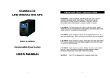
User guide
1 IMPORTANT SAFETY INSTRUCTIONS
Thank you for selecting this uninterruptible power system (UPS) XP PRO series. It will
provide you with better protection for your connected equipment.
Please read this manual!
This manual informs you about safety, installation and operating instructions that will help
you derive the fullest performance from the UPS..
Please save this manual !
It includes important instructions for the safe and good use of this UPS.
Should the UPS fail to function correctly we recommend to contact your local service center.
Please save or recycle the packaging materials!
The UPS shipping materials were designing with great care to provide protection from
transportation related damage. Please keep the original packaging. In case of return to the
after-sales service, it will be required.
Damage sustained during transit is not covered under the warranty.

INFOSEC UPS SYSTEM - 4, rue de la Rigotière - 44700 Orvault - France - www.infosec.fr
Hot Line : tél : +33(0)2 40 76 15 82 - fax : +33 (0)2 40 94 29 51- [email protected] - 10 05 04 205 02
- 2 -
2 CAUTION
¾ The UPS contains voltages that are potentially hazardous. All repairs should be
performed by qualified service personal.
¾ The UPS has its own internal energy source (battery). The output receptacles may be
alive even when the UPS is not connected to an AC supply.
¾ Do not plug laser printer.
¾ The UPS is suitable only to computers and electronic equipment with substantially
rectifier or capacitive loads. It is not suitable to electronic equipment with significant
inductive loads, such as motors & fluorescent lamps.
¾ Be sure to operate within the power rating of the UPS. Below 1/2 or 1/3 of rated
power is recommended for longer backup time & longer battery life.
¾ Do not place the UPS near excessive humidity, under sunshine, or close to heat-emitting
sources.
¾ If the UPS is out of order, please unplug power cord and consult your dealer right away.
Do not remove cover if there is no serviceable part inside.
¾ The unit should be supplied by grounded source. Do not operate the unit without ground
source.
¾ The socket-outlet should be installed near the equipment and be easily accessible.
¾ Do not plug the UPS power cord into itself. That will result in a safety hazard.
¾ Installation should be performed by a qualified technician or electrician in accordance
with local electrical codes.

INFOSEC UPS SYSTEM - 4, rue de la Rigotière - 44700 Orvault - France - www.infosec.fr
Hot Line : tél : +33(0)2 40 76 15 82 - fax : +33 (0)2 40 94 29 51- [email protected] - 10 05 04 205 02
- 3 -
3 INTRODUCTION
3.1 System Description
The XP PRO product is line interactive UPS with the newest technology and powerful
function. The Line Interactive UPS with AVR function allows input voltage range from 75% to
125%, including on line voltage boost-up & buck down. An ideal protection equipment for
critical connected loads.
In addition, this UPS provides advanced single telephone line or modem surge suppression
through the modular connectors on the back panel.
The XP PRO UPS and RUPS 2000 monitoring software make your computer operate
intelligent and provide you with the ability of a perfect protection of your critical devices.
3.2 Features
¾ Line interactive design.
¾ User-friendly LCD display.
¾ Provides boost and buck AVR to stabilize input voltage.
¾ Provides lightning, surge, overload, and short-circuit protection.
¾ Built-in battery charger and battery over drain protection.
¾ No load auto shutdown (Dip switch set up).
¾ Load level and Battery level display.
¾ Buzzer alarm auto-reset (Dip switch set up).
¾ Auto restart when AC recovery.
¾ Cold start function (Dip switch set up).
¾ Tel / Modem / Fax protection against power surge.
¾ Bundle software : Automatically save your valuable files before auto shutdown.

INFOSEC UPS SYSTEM - 4, rue de la Rigotière - 44700 Orvault - France - www.infosec.fr
Hot Line : tél : +33(0)2 40 76 15 82 - fax : +33 (0)2 40 94 29 51- [email protected] - 10 05 04 205 02
- 4 -
4 SYSTEM CONCEPT
The purpose to present this chapter is to give you more precise conception about how UPS
works.
4.1 Block Diagram
AVR.
INV.
CHA.
N.F. N.F.
INPUT
OUTPUT
Fig. 1 shows how UPS works.
4.2 Normal Operation
There are two main loops when AC utility is normal : the AC output loop and the battery
charging loop. The AC output gets power from AC utility input and pass through AVR to
support power to load. In the same time, the AC utility input is converted by AC/DC CHA and
support charging power to charge batteries.
AVR.
INV.
CHA.
N. F. N. F.
INPUT
OUTPUT
Fig. 2 shows how the UPS works when AC Utility normal.
4.3 AC Utility Failure
If AC utility fails, the UPS quickly detects the problem and activates the inverter. The DC/AC
inverter changes DC power from the batteries into AC and provides continuous
uninterruptible power to load.
AVR.
INV.
CHA.
N.F. N.F.
INPUT
OUTPUT
Fig. 3 shows how the UPS works when AC Utility Failure

INFOSEC UPS SYSTEM - 4, rue de la Rigotière - 44700 Orvault - France - www.infosec.fr
Hot Line : tél : +33(0)2 40 76 15 82 - fax : +33 (0)2 40 94 29 51- [email protected] - 10 05 04 205 02
- 5 -
5 OVERVIEW
5.1 Front Panel
1. Master Power Switch: Turn ON/OFF the UPS.
2. Line-On: AC Normal .
3. AVR Protection : When AVR is working under regulation mode, the light will turn on.
4. Backup mode: Battery in backup
5. Over Load: If the UPS is overloaded, this light will turn on and the alarm will beep.
6. UPS Cut-Off: Overload or cut-off
7. Battery Level: A bar graph showing how much of the UPS battery is being used.
8. Load Level: A bar graph showing how much of the UPS power is being used.
5.2 Rear Panel
1. AC line input socket: Connect power cable from the UPS to AC utility.
2. AC input fuse: Contain the fuse to protect the UPS from over current from incoming AC utility.
3. Output receptacles: Connect power cables of computer equipment to these outlets.
4. Computer interface: This socket combines relay contact signals and RS-232
signals(Option) on DB9 connector.
5. Phone / Fax / Modem jack: Telecom transfer ports provide users to extend the
applications.
6. EXT. Battery: no available
7. UPS setup switch:
Dip1.Low load(below 50w) auto-shut OFF.
Low load auto-shut ON.
Dip2. DC-start ON.
DC-start OFF.
Dip3. Buzzer auto-reset OFF.
Buzzer auto-reset ON.
1

INFOSEC UPS SYSTEM - 4, rue de la Rigotière - 44700 Orvault - France - www.infosec.fr
Hot Line : tél : +33(0)2 40 76 15 82 - fax : +33 (0)2 40 94 29 51- [email protected] - 10 05 04 205 02
- 6 -
Rear Panel (2U): XP PRO RM 1000VA
1
2
1
2
3
3
4
4
5
5
6
6
Rear Panel (3U): XP PRO RM 1500 / 2000 / 2500 / 3000 VA
2
1
3
4
5
6
IEC-320:
7
NEMA5-15R:
2
1
3
4
5
6
7
IEC
–
320 :
NEMA5
–
15R
:

INFOSEC UPS SYSTEM - 4, rue de la Rigotière - 44700 Orvault - France - www.infosec.fr
Hot Line : tél : +33(0)2 40 76 15 82 - fax : +33 (0)2 40 94 29 51- [email protected] - 10 05 04 205 02
- 7 -
5.3 Position
XP PRO UPS may be installed either in a horizontal or in a vertical position. It is provided
with one UPS stand to stabilize the UPS in tower position and two angle flat brackets allow
the installation of the UPS as a 19" equipment rack.
Tour Position
Rack Position
Stand to stabilize UPS
Two Angle flat brackets

INFOSEC UPS SYSTEM - 4, rue de la Rigotière - 44700 Orvault - France - www.infosec.fr
Hot Line : tél : +33(0)2 40 76 15 82 - fax : +33 (0)2 40 94 29 51- [email protected] - 10 05 04 205 02
- 8 -
6 INSTALLATION AND OPERATION
Upon receipt of the UPS, inspect the shipping carton for damage. If there is any obvious
damage, immediately report it to the selling dealer or the delivering carrier. If there is no
damage to the shipping carton, unpack the unit and inspect the unit for damage.
The UPS is designed for installation in a protected environment within a temperature range
from 32°F to 104°F and relative humidity of 0∼90% without condensation. Do not block inlets
and outlets. Install the system in a location free from excessive dust and chemical fumes.
Check the identification label to verify the UPS voltage and power rating match the available
line voltage and load requirements.
Installation:
1. Check if the main switch on the UPS front panel is in the off position and insure that the
voltage of the AC utility source corresponds to the nameplate on the UPS rear panel.
2. Plug the power cable into the grounded socket. If indicators of LINE-ON & CUT-OFF
LCD light on, it means AC power is normal, but UPS is under CUT-OFF status and it will
automatically start to charge by itself.
3. Push the main switch, then the Load Level LCD will light on for 2 seconds and CUT-OFF
LCD will light off. The UPS is ready to start working normally.
4. Connect your PCs to the UPS and then turn them on. Be sure to check the Load Level
LCD indicator and do not overload it over 100%. To simulate AC failure (simply by
disconnecting the AC power) may help to insure whether UPS is in good condition or
not. When disconnecting the UPS from AC power, the BACKUP LCD lights on and the
alarm is sounding every 3 seconds. If the CUT-OFF LCD is on, it means UPS fault or
BATTERY fault. Then you have to contact your local service center.
5. When battery approaches low level, alarm will beep every second until auto shut down.
6. The 4 conditions UPS will automatically shut down :
a. Battery low
b. Short circuit
c. Overload
d. UPS fault

INFOSEC UPS SYSTEM - 4, rue de la Rigotière - 44700 Orvault - France - www.infosec.fr
Hot Line : tél : +33(0)2 40 76 15 82 - fax : +33 (0)2 40 94 29 51- [email protected] - 10 05 04 205 02
- 9 -
7 COMPUTER INTERFACE
The computer interface (DB9 port) on the back of the UPS may be connected to a host
computer. This port allows the computer to monitor the status of the UPS and control the
operation of the UPS. The RUPS2000 provides complete On-Screen power management to
the UPS and computer systems. Its major functions normally include some or all the
following:
• Real-time UPS status on screen.
• All history records in memory.
• Auto orderly shutdown for computer & UPS.
• Multi-server support.
• Auto file save even without filename preset.
• Scheduled switch on/off daily or weekly.
Pin out information:
PIN# Description I/O
Input
Output
Output
PIN1
PIN2
PIN3
PIN4
PIN5
PIN6
RS232 DTR, must keep in high state
Line fail, normally open, active close
N.C.
Common for PIN 2,5
Battery low, normally open, active close
Two purposes on this pin
(1)Remote shut down, keep this pin high
(+5~+12V) for 3S will turn off the UPS
(2)RS232 Receiver Rx
Input
PIN7 Ground for PIN 6,9
PIN8 N.C.
PIN9 RS232 Transmitter TX
1234
5
6789
1
2
3
4
5
6
7
8
9
Output

INFOSEC UPS SYSTEM - 4, rue de la Rigotière - 44700 Orvault - France - www.infosec.fr
Hot Line : tél : +33(0)2 40 76 15 82 - fax : +33 (0)2 40 94 29 51- [email protected] - 10 05 04 205 02
- 10 -
8 BATTERY FACTS
The battery is the only periodically serviceable parts in the UPS. An expected life is approx.
3∼5 years. However, frequent long discharges or ambient temperatures above 25°C (80°F)
will shorten battery life. Therefore, it is recommended to replace the batteries every 3 years
after initiating the unit.
Recharge batteries every 3 months is necessary if it is not in use because it may cause
batteries over-drain.
WARNING
Only a qualified technician should replace the battery. Batteries have high short-
circuit current capacity; mistakes in connecting or disconnecting can cause
connections to arc or weld and could cause severe burns.
STORAGE
The UPS should only be stored if the battery is fully charged. Avoid storage temperatures
above 25°C (80°F) as battery life is significantly shortened. Every 90 days remove the unit
from storage and plug it in for 24 hours to recharge the batteries. Batteries may be damaged
if left in storage and not recharge every 90 days.
IMPORTANT NOTICE
Please use same type and same rating of batteries for replacement.
Do not replace it with the battery that exceeds specified rating.

INFOSEC UPS SYSTEM - 4, rue de la Rigotière - 44700 Orvault - France - www.infosec.fr
Hot Line : tél : +33(0)2 40 76 15 82 - fax : +33 (0)2 40 94 29 51- [email protected] - 10 05 04 205 02
- 11 -
9 SPECIFICATIONS
Capacity VA 1000VA 1500VA 2000VA 2500VA 3000VA
Voltage
110VAC, 115VAC, 120VAC, 220VAC,
230VAC or 240VAC ±25%
Input
Frequency 50Hz or 60Hz ±5%
Voltage
(Batt. Mode)
110VAC, 115VAC, 120VAC, 220VAC,
230VAC or 240VAC±5%
Frequency 50Hz or 60Hz ±1Hz
Waveform Modified sine wave
Output
Transfer
Time
Less than 4ms (typical)
Battery
Type
12V / 7AH *2PCS 12V / 7AH *4PCS 12V / 9AH *4PCS
Battery
Recharge
Time
5 hours to 90% of full capacity
Indicator LCD
LCD indicator for line on, battery back-up, AVR protection,
Overload and cut-off, Load and battery level
Battery
Back-up
Sounding every 3 seconds
Battery Low Sounding every 1 second
Alarm
Overload Continue beeping sound
Overload Fuse & current limited
Short Circuit Fuse & current limited & cut-off
Protection
Batt. Low
Cut-off
No battery drain after cut-off
Physical
Dimension,
D*W*H
2U / 280*440*88 mm
3U / 280*440*132 mm
Operating
Temperature
0°C-40°C (32°F-104°F) at full load,
0~90% relative humidity (non-condensing)
Environment
Noise Level Less than 40db (at 1 meter)
Interface
Contact
Closure
DB9 connector for connecting
with Rups-2000 software

INFOSEC UPS SYSTEM - 4, rue de la Rigotière - 44700 Orvault - France - www.infosec.fr
Hot Line : tél : +33(0)2 40 76 15 82 - fax : +33 (0)2 40 94 29 51- [email protected] - 10 05 04 205 02
- 12 -
10 TROUBLE SHOOTING
If the UPS failed to operate properly, please review the following checks firstly. If the problem
remains, please consult sales agent for service.
• Is the Master power switched on?
• Is the UPS plugged into a correctly working outlet?
• Is the line voltage within the rating specified?
• Is the fuse on the rear panel blown?
• Is the UPS over loaded?
• Is battery not fully charged? Dead battery? Charger failure?
Please provide the following information when call for service to +33 2 40 76 15 82.
→ Model number, serial number.
→ Date of the problem occurred, date of purchase.
→ Full description of the problem including load, LCD, and alarm status, installation condition,
working environment, etc.
Trouble-Shooting Chart
Problem Possible Cause Caution To Take
Front panel switch in off
position.
Turn on switch.
Rear panel fuse burnout. Replace fuse restart UPS.
No light, and no alarm
(UPS not on)
Power cord lose Check input power.
Power cord lose Check input power.
No “Line-on LCD” light,
and alarm beeps every few
seconds.
AC Fuse burnout.
Replace fuse, if problem
remains, call for service.
Backup time is less than
the rating.
Battery is not fully
charger failure.
Recharge the battery
for at least 6 hours,
re-test the backup time.
If problem remains,
call for service.

INFOSEC UPS SYSTEM - 4, rue de la Rigotière - 44700 Orvault - France - www.infosec.fr
Hot Line : tél : +33(0)2 40 76 15 82 - fax : +33 (0)2 40 94 29 51- [email protected] - 10 05 04 205 02
- 13 -
Notice d'utilisation
1 IMPORTANT
Merci pour le choix de cet onduleur (UPS) de la gamme XP PRO RM. Il vous fournira la
meilleure protection pour votre matériel.
Prendre connaissance de ce manuel!
Ce manuel vous informe sur la sécurité, ainsi que sur les instructions d’installation et de bon
fonctionnement de ce matériel afin de vous offrir un maximum de performance et de
longévité.
Garder de coté ce manuel !
Il indique les conditions de sécurité pour son utilisation ainsi que des informations pour un
bon fonctionnement.
En cas de problème vous pouvez contacter notre SAV au 02.40.76.15.82
Vérification emballage !
L’emballage de cet appareil a été conçu pour fournir une bonne protection lors de son
transport. Si le matériel arrive endommagé, prendre immédiatement contact avec le
transporteur.
Nous vous conseillons de converser cet emballage, il sera indispensable pour un éventuel
retour de l’onduleur en nos locaux.

INFOSEC UPS SYSTEM - 4, rue de la Rigotière - 44700 Orvault - France - www.infosec.fr
Hot Line : tél : +33(0)2 40 76 15 82 - fax : +33 (0)2 40 94 29 51- [email protected] - 10 05 04 205 02
- 14 -
2 AVERTISSEMENT
¾ L’onduleur délivre des tensions potentiellement dangereuses. Toute intervention doit
être réalisée par un personnel qualifié.
¾ L’onduleur possède sa propre source d’énergie interne (batterie). Les prises de sortie
peuvent délivrer une tension même si l’onduleur n’est pas raccordé au secteur.
¾ Ne pas brancher d’imprimante laser.
¾ L’onduleur est conçu pour l’alimentation d’ordinateurs et d’équipements électroniques
avec alimentation à découpage ou charge capacitive. Il est déconseillé pour les charges
inductives telles que les moteurs et les lampes fluorescentes.
¾ S’assurer que la charge à protéger est en dessous de la puissance nominale de
l’onduleur. Une charge de 1 /2 ou 1/3 de la puissance nominale est recommandée
pour une durée de vie et une autonomie plus grandes de la batterie.
¾ Ne pas placer l’onduleur à proximité d’une source de chaleur, ne pas exposer au soleil ni
à une humidité excessive.
¾ En cas de non fonctionnement de l’onduleur, débrancher le cordon d’alimentation et
appeler votre revendeur. Ne pas démonter l’onduleur.
¾ L’onduleur doit être alimenté impérativement avec une prise de courant possédant une
borne de terre.
¾ Les prises de sortie doivent être facilement accessibles.
¾ Ne pas raccorder l’entrée de l’onduleur sur ses prises de sortie, ceci provoquerait sa
destruction.
¾ L’installation doit être réalisée par un électricien qualifié en conformité avec les normes
en vigueur.

INFOSEC UPS SYSTEM - 4, rue de la Rigotière - 44700 Orvault - France - www.infosec.fr
Hot Line : tél : +33(0)2 40 76 15 82 - fax : +33 (0)2 40 94 29 51- [email protected] - 10 05 04 205 02
- 15 -
3 INTRODUCTION
3.1 Description Générale
L’onduleur fournit une alimentation sans interruption pour protéger vos équipements
électroniques sensibles et ordinateurs contre les coupures de tension et perturbations du
secteur. Un régulateur de tension en mode secteur permet de compenser les baisses de
tension (de 75% à 125%) sans puiser d’énergie dans les batteries.
Une protection Fax/Modem contre les surtensions sur la ligne téléphonique est située à
l’arrière de l’appareil.
Le logiciel RUPS2000 permet la communication avec l’UPS (contacts secs).
3.2 Caractéristiques
¾ Design Line interactive.
¾ Ecran LCD.
¾ Autorégulation (AVR) pour compenser les variations de tensions.
¾ Protection contre surtension transitoire, surcharge et, court-circuit.
¾ Conçu avec un chargeur batterie et une protection d’autodécharge.
¾ Mode éco : arrêt automatique si pas de charge en mode batterie (Réglage par micro-
switch).
¾ Voyants indiquant les niveaux de la batterie et de la charge.
¾ Buzzer alarm auto-reset (Réglage par micro-switch).
¾ Démarrage automatique au retour secteur.
¾ Démarrage sur batterie (Réglage par micro-switch).
¾ Protection Tel / Modem / Fax / Internet contre les variations de tension
¾ Logiciel de fermeture automatique des fichiers et arrêt de l’onduleur.

INFOSEC UPS SYSTEM - 4, rue de la Rigotière - 44700 Orvault - France - www.infosec.fr
Hot Line : tél : +33(0)2 40 76 15 82 - fax : +33 (0)2 40 94 29 51- [email protected] - 10 05 04 205 02
- 16 -
4 PRINCIPE DE FONCTIONNEMENT
L’objectif de ce chapitre est de vous donner une idée du fonctionnement de l’onduleur.
4.1 Diagramme
AVR.
INV.
CHA.
N.F. N.F.
INPUT
OUTPUT
Fig. 1 schématisation de l’UPS.
4.2 Fonctionnement normal : Mode Secteur
La tension du secteur alimente deux circuits, le premier va vers la sortie et le second vers le
chargeur batterie. La tension d’entrée (INPUT) traverse l’AVR et est acheminée vers la sortie
(OUTPUT) pour alimenter la charge. Parallèlement, le circuit AC/DC CHA convertit la tension
d’entrée pour recharger les batteries.
AVR.
INV.
CHA.
N.F. N.F.
INPUT
OUTPUT
Fig. 2 UPS secteur présent.
4.3 Mode Batterie
En cas de panne du secteur, l’onduleur va rapidement le détecter et activer le circuit
INVERTER. L’INVERTER DC/AC converti la tension continue provenant des batteries en
tension 230Vac pseudo sinusoïdale pour alimenter la charge.
AVR.
INV.
CHA.
N.F. N.F.
INPUT
OUTPUT
Fig. 3 Fonctionnement de l’UPS en mode batterie

INFOSEC UPS SYSTEM - 4, rue de la Rigotière - 44700 Orvault - France - www.infosec.fr
Hot Line : tél : +33(0)2 40 76 15 82 - fax : +33 (0)2 40 94 29 51- [email protected] - 10 05 04 205 02
- 17 -
5 DESCRIPTION
5.1 Face Avant :
1. BOUTON ON/OFF: bouton MARCHE / ARRET.
2. SECTEUR PRESENT: Voyant Mode secteur, secteur présent.
3. AVR : voyant mode AVR éclairé quand l’UPS régule la tension.
4. ONDULEUR SUR BATTERIE: Fonctionnement en Mode batterie, secteur absent.
5. SURCHARGE: UPS en surcharge, le voyant s’éclaire et l’alarme sonne en continu.
6. SORTIE UPS COUPEE: Défaut onduleur.
7. NIVEAU BATTERIE: % niveau de décharge des batteries en mode batterie.
8. NIVEAU DE CHARGE: % niveau de charge indique la quantité de matériel connecté.
5.2 Face Arrière:
1. PRISE ALIMENTATION SECTEUR : Prise d’entrée pour le câble d’alimentation.
2. FUSIBLE D’ALIMENTATION : Logement du fusible de protection d’entrée.
3. PRISES DE SORTIE: Prises de sortie pour connecter le matériel à protéger.
4. INTERFACE ORDINATEUR : Port de communication DB9.
5. PROTECTION TEL/FAX/MODEM : connexion RJ téléphone/fax.
6. EXT. Battery: Absent sur ce modèle.
7. MICRO SWITCH REGLAGE UPS:
Dip1. En mode batterie : si charge < 50W pas d’arrêt automatique de l’UPS.
En mode batterie : si charge < 50W arrêt automatique de l’UPS.
Dip2. Possibilité de démarrage sur batteries activée.
Possibilité de démarrage sur batteries désactivée.
Dip3. Alarme sonore auto-reset OFF.
Alarme sonore auto-reset ON.
1

INFOSEC UPS SYSTEM - 4, rue de la Rigotière - 44700 Orvault - France - www.infosec.fr
Hot Line : tél : +33(0)2 40 76 15 82 - fax : +33 (0)2 40 94 29 51- [email protected] - 10 05 04 205 02
- 18 -
Face Arrière 2U : XP PRO RM 1000VA
1
2
1
2
3
3
4
4
5
5
6
6
Face Arrière 3U : XP PRO RM 1500 / 2000 / 2500 / 3000 VA
2
1
3
4
5
6
IEC-320:
7
NEMA5-15R:
2
1
3
4
5
6
7
IEC
–
320 :
NEMA5
–
15R
:
/