Page is loading ...

Serious injury or death can occur from the rack tipping over. To prevent this, the rack
must be secured to a wall, especially in earthquake -prone areas, or where surfaces are uneven, and where
children and/or pets are present.
Different wall materials require different types of fasteners. Use fasteners suitable for your specific type of
wall. If you are uncertain about what type of fastener to use, then please contact your local hardware store.
If you have questions or comments, contact us.
Pour toute question ou tout commentaire, nous contacter.
Si tiene dudas o comentarios, contáctenos.
1-844-377-8451 • www.dewalt.com
INSTRUCTION MANUAL
GUIDE D’UTILISATION
MANUAL DE INSTRUCCIONES
INSTRUCTIVO DE OPERACIÓN, CENTROS DE SERVICIO Y PÓLIZA
DE GARANTÍA. ADVERTENCIA: LÉASE ESTE INSTRUCTIVO ANTES
DE USAR EL PRODUCTO.
DXST10000
Titan Industrial Rack 6-Foot (182.88 cm) Tall / 4-Shelf
Étagère industrielle titan 1,83 m (6 pi) de hauteur / 4 tablettes
Estantería industrial titan 6 pies (182.88 cm) de altura / 4 estantes
Copyright © 2018 DEWALT.
D
EWA LT
®
and the DEWALT Logo are trademarks of the DEWALT Industrial Tool Co., or an affiliate thereof
and are used under license. The yellow/black color scheme is a trademark for D
EWALT
power tools & accessories.
JS PRODUCTS | 6445 MONTESSOURI STREET, LAS VEGAS, NV 89113
SAVE THESE INSTRUCTIONS
READ ALL INSTRUCTIONS
TECHNICAL SPECIFICATIONS
Parts List
IF YOU HAVE ANY QUESTIONS OR COMMENTS ABOUT THIS OR ANY DEWALT TOOL,
CALL US TOLL FREE AT: 1-844-377-8451
WARNING! Read and understand all instructions. This manual contains
important safety and operating instructions. Please read this manual carefully
before assembling this storage rack and save it for reference.
Technical Specifications
Total Capacity 10,000 lb (4,535.9 kg)
*when weight is evenly distributed
Capacity per Shelf 2,500 lb (1,133.9 kg)
*when weight is evenly distributed
Height 72" (182.8 cm)
Width 77" (195 cm)
Depth 24" (61 cm)
No. Description Qty.
1 Vertical Beam 2
2 Pre-Bolted Vertical Assembly 2
3 Vertical Assembly Bolt 4
4 Crossbeam 8
5 Shelf Support Strap 20
6 Safety Strap With Weld Nut 12
7 Safety Strap Bolt 24
8 Wire Grid 3
9 Laminate Deck 1
• Read all instructions thoroughly.
• Remove all components from the box, and lay them on the floor in an orderly fashion.
• Wear eye protection.
• Be cautious of sharp edges.
• Keep this information for further reference.
(MAY18) Part No. 56829 DXST10000 Copyright © 2018, D
EWALT
1
2
4
9
8
WARNING:
WARNING:
Serious or fatal crushing injuries can occur from rack tipping over. To prevent this, the
assembled rack must always be secured to a wall, especially in earthquake-prone environments, where
surfaces are uneven, and where children and/or pets are present.
NOTE: For ease of assembly, two (2) vertical beams feature pre-bolted horizontal and diagonal beams, as
well as pre-attached U-bracket covers.
1. Place one (1) vertical beam and one (1) pre-bolted vertical beam on the floor, parallel to one another
(about 24"/60.9 cm apart). The widest part of the teardrop-shaped hole pattern on each beam should
be facing upward (or away from you). (Fig. 1)
2. There are two versions of the U-bracket covers - an “A” side and a “B” side. Before moving forward,
cover the U-shaped brackets on the vertical beam with the covers by mirroring the covers on the pre-
bolted vertical assembly.
3. Insert the free end of the diagonal beam into the free end of the horizontal beam. Align the holes, and
insert both beams into the U-shaped bracket at the top of the opposing vertical beam. Use the included
hex key or drill bit to thread the vertical assembly bolt through the holes and into the weld nut attached
to the U-shaped bracket. Do not fully tighten the bolt yet. (Fig. 2)
Expandable Upright Frame Instructions (Fig. 1-2)
GENERAL SAFETY
NEVER EXCEED THE FOLLOWING WEIGHT LIMITS
FOR THIS RACK
SPECIFIC SAFETY FOR WALL MOUNT BRACKET
• Keep work area clean and dry.
• Use correct/recommended tools for the job.
• Never leave unattended tools plugged in or running.
• Never force a part into place.
• Wear appropriate safety apparel for the job you are doing.
• Wear safety glasses/goggles.
• Never crawl, sit, stand, or climb on the rack.
• Keep small parts away from children. Never leave a small child unattended while assembling.
• Always use common sense – your personal safety is your responsibility.
• Maximum load for each shelf: Up to 2,500 lb (1,133.9 kg) when weight is evenly distributed.
• It is recommended that the heaviest load be placed on the bottom shelf.
Definitions: Safety Guidelines
The definitions below describe the level of severity for each signal word. Please
read the manual and pay attention to these symbols.
Indicates a potentially hazardous situation which, if not avoided, could
result in death or serious injury.
WARNING:
Indicates a potentially hazardous situation which, if not avoided, may
result in minor or moderate injury.
CAUTION:
(Used without word) Indicates a safety related message.
Indicates a practice not related to personal injury which, if not avoided,
may result in property damage.
NOTICE:
No. Description Qty.
10 Locking Shelf Pin 16
11 Locking Grid Clip 12
12 Carriage Bolt 2
13 10 mm Nut 2
14 10 mm Wrench 1
15 4 mm Hex Key 1
16 4 mm Hex Bit 1
17 Wall Mount Bracket Assembly 1
18 U-Bracket Cover 4
WARNING:
Tools Required for Rack Assembly: 4 mm Hex Key (included) OR 4 mm Hex Bit (included); Rubber
Mallet (not included).
3
5
7
6
10
11
12
17
16
15
14
13
BEFORE YOU BEGIN:
18

ROCK BRACKET UPWARDS
FIG. 3
FIG. 1
FIG. 4
FIG. 2
FIG. 5
One Year Limited Warranty
DEWALT will replace this Industrial Rack due to faulty materials or workmanship for one year from the date
of purchase (please be sure to keep your receipt). This warranty does not cover part failure due to normal
wear or rack abuse. This warranty does not apply to accessories or damage caused where repairs have
been made or attempted. For further detail of warranty coverage, call 1-844-377-8451.
In addition to the warranty, D
EWALT racks are covered by our:
90 Day Money Back Guarantee
If you are not completely satisfied with the performance of your DEWALT Industrial Rack for any reason, you
can return it within 90 days from the date of purchase with a receipt for a full refund – no questions asked.
Latin America
This warranty does not apply to products sold in Latin America. For products sold in Latin America, see
country specific warranty information contained in the packaging, call the local company or see website for
warranty information.
JS PRODUCTS | 6445 MONTESSOURI STREET, LAS VEGAS, NV 89113
CONSERVER CES CONSIGNES
POUR TOUTE QUESTION OU REMARQUE AU SUJET DE CET OUTIL OU DE TOUT AUTRE
OUTIL DEWALT, COMPOSEZ LE NUMÉRO SANS FRAIS: 1-844-377-8451.
Avertissement ! Lire et comprendre toutes les directives.
Ce manuel contient des consignes de sécurité et d’utilisation
importantes. Veuillez lire attentivement ce manuel avant d’assembler
cette étagère de rangement et le conserver à titre de référence.
(MAY18) Part No. 56829 DXST10000 Copyright © 2018, DEWALT
DEWA LT
®
et le logo DEWALT sont des marques de commerce de DEWALT Industrial Tool Co. ou d’une
société affiliée à cette dernière et sont utilisés sous licence. L’agencement de couleurs jaune et noir est une
marque de commerce des outlils électriques et accessorires D
EWALT.
Les définitions ci-dessous décrivent le niveau de danger pour chaque mot indicateur
employé. Lire le mode d’emploi et porter une attention particulière à ces symboles.
indique une situation potentiellement dangereuse qui, si elle n’est
pas évitée, pourrait entraîner la mort ou des blessures graves.
.
indique une situation potentiellement dangereuse qui, si elle n’est pas
évitée, pourrait entraîner des blessures légères ou modérées
(Si utilisé sans aucun terme) Indique un message propre à la sécurité.
indique une pratique ne posant aucun risque de dommages corporels
mais qui par contre, si rien n’est fait pour l’éviter, pourrait poser des risques de
dommages matériels.
AVIS :
Définitions : Règles de sécurité
4. Swing out the bottom horizontal beam, and insert it into the U-shaped bracket at the bottom of the
opposing vertical beam. Thread a vertical Aassembly bolt through the holes and into the weld nut. Do
not fully tighten the bolt. (Fig. 2)
5. Repeat Steps 1-4 to assemble the second upright frame. Once both are assembled, fully tighten the
bolts on all four corners. Be careful not to over-tighten the bolts; there should be no deformation of the
U-shaped brackets and/or horizontal beams.
(61 cm)
2 ft
TOP HORIZONTAL BEAM
BOTTOM HORIZONTAL BEAM
DIAGONAL
BEAM
24"
(61 CM)
LOCKING
PIN HOLE
NOTE: It is recommended for one person to hold the upright frames in place while a second person installs
the crossbeams.
1. There is a set of locking tabs at both ends of every crossbeam. To begin assembly, take one crossbeam
and insert the tabs into two of the holes on the lower portion of one upright frame. Engage the locking
tabs into the holes using a downward motion. The locking pin hole should be at the top. Make sure the
end of the crossbeam is flush against the upright frame. (Fig. 3)
2. Repeat for the opposite side of the upright frame. Tap the ends of the crossbeam closest to the upright
frames with a rubber mallet until fully seated. The crossbeam and locking tabs should easily slip into
place. If they do not, then recheck the alignment of the teardrop-shaped holes and tabs. Too much
force may damage the interlock between the crossbeam and upright frame. (Fig. 4)
3. Using the methods listed above, install another crossbeam to the opposite side of the upright frames,
parallel to the first crossbeam you installed. Make sure both crossbeams are at the same level.
4. Continue by installing the last three sets of crossbeams to the upright frames. Make sure the
crossbeams are attached at the same level on both sides. (Fig. 5)
Crossbeam Instructions (Fig. 3-5)
FIG. 6
FIG. 12
FIG. 9
FIG. 7
FIG. 13
FIG. 10
FIG. 8
FIG. 14
FIG. 11
NOTE: There are three (3) safety straps with weld nuts and five (5) shelf support straps on every set
of crossbeams. (Fig. 6)
1. Starting with the lowest set of crossbeams, place a safety strap with weld nut between the lower ridges
of the crossbeams where two sets of holes have been pre-drilled. Thread a safety strap bolt up through
the bottom of the pre-drilled holes and through the weld nuts, and fully tighten with the included hex key
or drill bit. Repeat for the last two straps on this set of crossbeams, and continue for remaining
nine straps. (Fig. 7)
2. Place a shelf support strap perpendicular to the crossbeams, and insert each end into the slots on each
ridge of the crossbeam. Repeat for the remaining 19 straps. (Fig. 8)
NOTE: Each wire grid consists of two sides - a “short” side and a “long” side. If you plan on sliding objects
on and off of the shelf from the front of the rack, then we recommend having the “short” side of the grid
facing upward. If you plan on sliding objects from the side of the rack, then we recommend having the
“long” side facing upward.
1. Place the laminate deck onto the top ridge of any set of crossbeams. If seated properly, it will “pop” into
place and lay evenly.
2. Place the wire grids onto the top ridge of remaining sets of crossbeams. If seated properly, it will “pop”
into place and lay evenly. (Fig. 12)
3. Place a locking grip clip at the outermost corner of the shelf with a wire grid. Make sure the rolled edge
with the groove is facing upward. (Fig. 13)
4. With one hand, apply pressure to the back of the clip. With your free hand, insert a flat-head screwdriver
(not included) into the small slot in the clip to spread the tine up and over the wire that is underneath.
5. Pull back on the screwdriver. The grooved channel in the clip should now match up with the wire
decking, which will help secure it to the shelf beam.
6. Repeat steps 3-5 for the remaining three corners of the wire grid, and then again for all the
remaining shelves.
7. There is a locking pin hole at both ends of every crossbeam. This is where the locking shelf pins are to
be installed. If a pin does not easily slip into place, then moderately tap the end of the crossbeam to
fully seat the locking tabs. (Fig. 14)
Shelf Support and Safety Strap Instructions (Fig. 6-8)
Wire Grid, Laminate Deck, and Locking Shelf Pin Instructions
(Fig. 12-14)
Wall Mounting Instructions (Fig. 9-11)
SHELF SUPPORT
STRAP (ON TOP)
SAFETY STRAP WITH
WELD NUT
(UNDERNEATH)
SAFETY STRAP WITH
WELD NUT
(UNDERNEATH)
SHELF SUPPORT
STRAP (ON TOP)
Serious injury or death can occur from the rack tipping over. To prevent this, the rack
must be secured to a wall, especially in earthquake -prone areas, or where surfaces are uneven, and where
children and/or pets are present.
Different wall materials require different types of fasteners. Use fasteners suitable for your specific type of
wall. If you are uncertain about what type of fastener to use, then please contact your local hardware store.
Drywall anchors and anchor screws are included with this rack; however, different wall materials require
different types of fasteners. Use fasteners suitable for your specific type of wall. If you are uncertain about
what type of fasteners to use, then please contact your local hardware store.
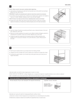
1. Take the U-shaped bracket and rock it up at an angle to attach it to the bottom inner channel of the
crossbeam. Once attached, the back portion will sit flush against the inside of the crossbeam. (Fig. 9)
2. Once attached, the U-shaped bracket can be moved from side to side (in between the two safety
straps). This allows for it to be attached to a 2 x 4 in the wall. (Fig. 10)
3. The L-shaped bracket has two sets of four square holes that allow you to adjust the distance of the
rack to the wall. Use two carriage bolts and two 10 mm nuts to attach the L-shaped bracket to the
bottom of the U-shaped bracket. (Fig. 11)
4. Position the rack so the flat end of the L-shaped bracket is touching the wall. Use a pencil to mark
the location of the four holes on the wall. Use the included drywall anchors, anchor screws, and the
appropriate tools if you’re securing the rack to drywall only. Be sure to follow standard instructions for
installing anchor screws. (Fig. 11)
WARNING:
Maximize your DEWALT Storage Options
NOTE:
• Connect multiple racks together to create the ultimate storage solution.
• Additional racks are sold separately.
/
