Page is loading ...

TrueDRY™ DH150
Dehumidification System
PROFESSIONAL INSTALLATION GUIDE
1
Assemble
2
Duct
3
Plumb
4
Wire
69-2271EFS-01
Must be installed by a trained, experienced technician
Read these instructions carefully. Failure to follow these instructions can
damage the product or cause a hazardous condition.

Installation Guide
69-2271EFS—01 ii
Read and save these instructions.
Need Help?
For assistance with this product please visit http://yourhome.honeywell.com
or call Honeywell Customer Care toll-free at 1-800-468-1502
® U.S. Registered Trademark.
Copyright © 2008 Honeywell International Inc. All rights reserved.
• DonotinstallTrueDRYDH150'sexhaustendwithoutducting.
• TrueDRYDH150isdesignedtobeinstalledindoorsinaspacethatisprotectedfromrainand
flooding.
• Installtheunitwithspacetoaccessthebackorsidepanelsformaintenanceandservice.Donot
installwithservicepanelsinaccessible.
• Avoiddirectingthedischargeairatpeople,oroverthewaterinpoolareas.
• Ifusednearapoolorspa,becertainthereisnochancetheunitcouldfallintothewaterorbe
splashed,andthatitispluggedintoagroundfaultinterrupt(GFI)outlet.
• Donotusethedeviceasabenchortable.
• Toensurequietoperation,donotplacethedevicedirectlyonthestructuralsupportsofthehome.
Providevibrationisolationtominimizenoise.
• Adrainpanmustbeplacedundertheunitifinstalledabovealivingareaoraboveanareawhere
waterleakagecouldcausedamage.
Table of Contents
About your new dehumidifier
Maintaining ideal humidity .................................................................................. 1
Controls ................................................................................................................ 2
Specifications ....................................................................................................... 3
Installation
InstallationChecklist ........................................................................................... 4
IntendedApplication ...........................................................................................4
Ducting:InstalltoFitYourApplication.............................................................. 6
Plumbing ...............................................................................................................7
TerminalDescriptions .......................................................................................... 7
Wiring .................................................................................................................... 8
Checkout ............................................................................................................ 10
Maintenance
Cleaning .............................................................................................................. 11
Troubleshooting ................................................................................................. 12
Parts List ............................................................................................................ 16
Warranty ............................................................................................................. 17

TrueDRY DH150
1 69-2271EFS—01
TheHoneywell TrueDRYDH150ensuresthe homeis maintainedat properhumiditylevels throughitshigh perfor-
mance and efficiency.
Benefits
• Removesupto150pintsofwaterfromtheindoorair.
• Canbeductedforwhole-househumiditycontrol,oroperate
unductedtoaddressmoistureproblemareassuchasanatticor
crawl space.
• Easyaccesspanelsmakesservicequickandsimple.
Maintaining Ideal Humidity
Dewpointsandrelativehumidity(RH)affectthewayyourbodysenses
heat. Higher humidity levels cause the air to feel much hotter than the
actualtemperature.WhenTrueDRYisinstalledproperly,yourcooling
equipmentmaynotrunasmuchbecausedehumidifiedairfeelscooler
than humid air.
About the TrueDRY DH150 Dehumidifier
Idealhumidityisdefinedbyindustry
experts*asbeingbetween40-60%on
anaverageannualbasis.Whenindoor
humidityexceeds60%,thehomeismore
susceptibletomoldandmildewgrowth.
TrueDRYDH150safeguardsagainstexces-
sive humidity in the home year-round.
*American Society of Heating, Refrigerating and Air
Conditioning Engineers (ASHRAE).
MCR24780
0102030405060708090100
OPTIMUM
ZONE
BACTERIA
VIRUSES
FUNGI
MITES
RESPIRATORY
INFECTIONS
ALLERGIC RHINITIS
AND ASTHMA
CHEMICAL
INTERACTIONS
OZONE
PRODUCTION
ASHRAE RECOMMENDED WINTER DESIGN LEVEL
00159095808570756065505540453035202510150
001 4418312316210215110117014011019979593919
59 631031421811411
0117014011018969493919098878
09 221711311901601201001896959391909887868584838
58 801501201997959391909988
878685848382818089787
08 199888786868583828181808979787777767574737
57 0897978787777767675757474737372727
17079696
07 271717171717070707969686867676666656564646
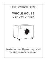
WHAT THE AIR FEELS LIKE
HOW HOT THE HEAT-HUMIDITY COMBINATION MAKES IT FEEL.
EXAMPLE: AIR AT 90ºF WITH 50% RH FEELS LIKE 96ºF TO THE HUMAN BODY!
RELATIVE HUMIDITY (PERCENTAGE)
EXTREME DANGER
EXTREME CAUTION
CAUTION
M27328
DANGER
AIR TEMPERATURE
(DEGREES FAHRENHEIT)
SOURCE: TEMPERATURE - HUMIDIY INDEX WAS DERIVED BY R.G. STEADMAN, JOURNAL OF APPLIED METEOROLOGY, JULY 1979.

Installation Guide
69-2271EFS—01 2
VisionPRO IAQ Total Comfort System (YTH9421C1010)
•Controlsbothheating/coolinganddehumidification.
•Sensorincludedfordisplayingoutdoortemperature.
•Intuitiveuserinterfaceforeasy7-daytemperatureprogramming
•Easy-to-readbacklitdigitaldisplay.
•Maintenanceandservicereminders.
•Controlsotherindoorairqualityequipmentwhenyou’reready.
TheTrueDRYDH150maybeusedwithoneofthefollowingexternalcontrols:
TrueIAQ Digital Control (DG115EZIAQ)
•Automaticadjustmentsmaintainidealhumidity.
•Sensorfordisplayingoutdoortemperatureandhumidity.
•Showsactualanddesiredhumiditysettings.
•Advancedventilationprogrammingincludeseconomizingandextreme
condition shutdown.
•Maintenanceandservicereminders
•Controlsotherindoorairqualityequipmentwhenyou’reready.
Control Options
Manual Dehumidistat (H8908DSPST) and Automatic Ventilation
Controls (W8150A1001)
•Manualhumiditycontrolwithintuitivecomfortsettings.
•Integratedhumiditychartforaccuratecontrolinchangingoutdoorconditions.
•AutomaticW8150ventilationcontroltoASHRAEindustrycode,orfor
continuous operation.

TrueDRY DH150
3 69-2271EFS—01
InstallTrueDRYDH150accordingtoNationalElectricCodes.
Dimensions:
Specifications
Product weight:134lbs
Shipping weight:164lbs
Shipping dimensions:281/4in.Hx42in.Wx24in.D
Media Filter:MERV11,16in.Hx16in.Wx2in.D
Drain connection:3/4-in.threadedfemaleNPT
connection,withattached3/4-in.maleconnection.
Duct connections:Round10in.and6in.inlets.Oval
10in.x4in.outlet.
Cabinet:20gaugegalvanizedsteelpowder-coat
painted.
Input ratings
•Electricalinputvoltage:120VAC—1Phase—60Hz
nominal
•Inputcurrent:6.9amps
Output ratings
•Power transformer to R/C terminals:24VAC,
0.85A
•Energy Performance:3.6pintsperkilowatthour
(KWH).
Standards and approval body requirements
ETLtestedperULstandard474(ducteddehumidifier.)
Dry-Bulb
Temp
Wet-Bulb
Temp
Intake
Humidity
Capacity
(Pints/Day)
80°F 70°F 60%RH 150
70°F 61°F 60%RH 116
60°F 52°F 60%RH 88
Home Size
(square ft)
Dehumidifier Capacity Required to Maintain Desired Indoor RH*
60% RH Indoor (pints/day) 50% RH Indoor (pints/day) 40% RH Indoor (pints/day)
2080 49–54 55–58 71–78
2600 61–68 65–72 90–97
3120 75–82 79–86 95–110
*Basedonextremeclimateswhereoutdoorhumidityis70-90%RH.Forlessextremeclimates,largerhomescanbe
adequatelyservedwithlesscapacity.Actualrequirementsmayvary.
Airflow versus external static pressure
(0–1 in. water pressure) with collars attached
0in.WG 415CFM
0.4inWG. 365CFM
FRONT VIEW
6 DIAMETER
REAR VIEW
SIDE VIEW
37-1/2 (953) WITHOUT COLLARS
39-1/2 (1003) WITH COLLARS
19-15/16
(506)
20-5/8 (524)
10 DIAMETER
M27792
Insulation:Rvalue1
Compressor: Rotary-style
Refrigerant:2lb.,R-410.A
Operating Temp Range (outside cabinet):
56ºF-95ºF(13ºC-35ºC)
Operating Humidity Range: 0-99%RH

Installation Guide
69-2271EFS—01 4
Tools Required
- 3/8-in.hexdrive
- Drillorduct-cuttingtool
- Wirestripper/cutter
- Standard screwdriver
- Ducttape
- 8-in. round duct and starter collar
- 18–22gauge,5-bandthermostatwire
- 1/2-in.diameterdrainline(8ft)
- 1/2-in.drainclamps(quantity2)
Materials Provided
- Sheetmetalscrews(quantity9)
- 6-in. plastic duct collar
- 10-in.plasticductcollar
- 10-in.ovalx4in.plasticductcollar
Options:
- 1/2-in.drainp-trap(mayberequiredbylocalcode)
- Externalhumiditycontrol
•Manualdehumidistat(H8908DSPST),Auto
Ventilation(W8150A1001)
•TrueIAQ(DG115EZIAQ)
•VisionPROIAQ(YTH9421C1010)
Installation Checklist
WARNING:Installationmustbeperformedbyaqualifiedservicetechnicianandmustcomplywithlocal
codes.Removepowertothedevicebeforeinstallingorservicingthedevice.Failuretoconnectthe
device according to these instructions may result in damage to the device or the controls.
Intended Application
Fortheidealinstallation,drawairfromthecentralpartofthehomeandreturnittoisolatedareasofthehomelike
thebedrooms,den,utilityroom,orfamilyroom.Theductworkoftheexistingsystemcanbeusedtosupplyairto
the home.

TrueDRY DH150
5 69-2271EFS—01
M27793
M27794
Door and Collar Assembly
Door Install
Inserttabonthebottomofthedoorbetweenthefoam
installation and the metal side.
Push down on the plastic door latch and swing door shut.
Oncethedoorisshutreleasethedoorlatch.
Collar Install
Removethe2roundducts,1ovalduct,3sealsandsmall
bagofmountinghardwarefrominsidetherectangle
opening.
Adheresealsontothebackofeachductandmountthe
ducts to the front of the dehumidifier using screws pro-
vided.

Installation Guide
69-2271EFS—01 6
FlexductisrecommendedinconnectingtotheTrueDRYDH150collarstoreducevibrationnoise.
M24745
Electrical requirements:
115VACoutlet.Groundfault
interrupter(GFI)recommended.
Duct Sizing:Fortotalductlengths,useroundorrectangularductsizedaccordingly:
- 10-inchforlessthan25-ft
- 12-inchformorethan25-ft
Fortheoptionalfreshairventilationport,useroundinsulatedductsizedaccordingly:
- 6-inchroundforlengthsoflessthan50-ft.
- 8-inchroundforlengthsgreaterthan50-ft,orifmorethan100-cfmisrequired
Ducting: Install to Fit Your Application
Idealwhen…
• RunningTrueDRYDH150withA/Coperation.
• Minimizingdischargeairtemperature(DAT)
increase is preferred.
• Spacedictates.
Idealwhen…
• RunningTrueDRYDH150oppositeA/C
operation.RunningwithA/Coperationrequires
damperontheexhaustporttominimize
backdraftwhenTrueDRYDH150isnotonbut
A/Cis.
• MinimizingDATincreaseispreferred.
• Spacedictates.
Idealwhen…
• Dryingaspecificareaofthehouse.
• RunningwithA/Coperationrequiresbackdraft
damperontheexhaustporttominimize
backdraftwhenTrueDRYDH150isnotonbut
A/Cis.
• MinimizingDATincreaseispreferred.
Idealwhen…
• RunningTrueDRYDH150withA/Coperation.
• Dryingaspecificareaofthehouse.
• MinimizingDATincreaseispreferred.
TrueDRYDH150canbeductedintothecentralforcedairsys-
tem,oroperateasastand-aloneindesignated,high-humidity
zoneswithinthehome,suchasabasementorcrawlspace.
A
Main Return to Main Return
SUPPLY
RETURN
AIR HANDLER
M27965
TrueDRY
B
Main Return to Main Supply
SUPPLY
RETURN
AIR HANDLER
TrueDRY
M27966
BACKDRAFT
DAMPER
C
Dedicated Return to Main Supply
SUPPLY
RETURN
AIR HANDLER
TrueDRY
M27967
BACKDRAFT
DAMPER
SEPERATE
RETURN
D
Dedicated Return to Main Return
SUPPLY
RETURN
AIR HANDLER
M27968
TrueDRY
SEPERATE
RETURN

TrueDRY DH150
7 69-2271EFS—01
Connect1/2-in.draintubetomaleconnectiondrain
outlet.Securedraintubetoconnectorwithhoseclamp.
Run drain hose continuously downhill to an approved
drain or condensate pump. Route to drain with a trap if
possible.
PlaceTrueDRYDH150onsupportsthatraisethebase
abovethetopflangesonthedrainpanbeneathit.
Raisingitwilloptimizedrainflowbygravity.
Plumbing
Terminal Descriptions
CAUTION: Low-voltage Hazard.
Cancauseequipmentdamage.
DisconnectHVACequipmentbeforebeginning
installation.
Afour-blockwiringterminalislocatedonthesloped
endofTrueDRYDH150.
* Note:OuterscrewssecureblocktoTrueDRY
DH150.Notforwiring.
DHUM: Compressorandfanoperationfordehumidification.
R: 24Vhot
FAN: Fanactivationonlyforventilation.
C: 24Vcommon
Bend10in.roundflexducttofitovertheDH150ovaloutlet.
Ducting to Oval Outlet

Installation Guide
69-2271EFS—01 8
Wiring
M27941
FAN
C
R
DHUM
M27795
1
2
3
4
DHUM
(COMPRESSOR
AND FAN)
R
FAN
C
1
3
2
GRN
GRN

TrueDRY DH150
9 69-2271EFS—01
Wire the TrueDRY DH150 according to the diagram that applies to your desired operation.
Followthisdiagramforductedoperationwithanexternalhumiditycontrol.
Wiring
TrueDRY
HVAC
MECHANICAL
DEHUMIDISTAT
THERMOSTAT
GYWRRc
GYWR C
M27797
DRY
CONTACTS
+
+
FAN
C
DPDT RELAY,
2.6A
DHUM
R
TrueDRY
HVAC
MECHANICAL
DEHUMIDISTAT
THERMOSTAT
GY
W
R
Rc
GYWR C
M27798
DRY
CONTACTS
DHUM
+
+
R
FAN
C
DPDT
RELAY,
2.6A
EARD-6
AT120
R
C
DAMPER
AUX
REMOTE
W8150A
G
R
C
C
W
G
Forductedoperationwithexternalhumidityandventilationcontrol,followthisdiagram.

Installation Guide
69-2271EFS—01 10
FollowthisdiagramifusingTrueDRYDH150withVisionPROIAQ.
FollowthisdiagramifusingTrueDRYDH150withapowereddehumidistatsuchasTrueIAQ(DG115EZIAQ).
Wiring
HVAC
THERMOSTAT
GYWRRc
M27799
IF A THERMOSTAT OTHER THAN A TH5110, TH5220, TH5320, TH6110, TH6220, TH6320, TH8110,
TH8320, OR TH8321 IS USED, A RELAY MAY BE REQUIRED TO ISOLATE THE G WIRE.
PROGRAM ISU SETTING 60 TO Ø TO FORCE SYSTEM FAN ON WITH DEHUMIDIFICATION CALL.
DHUM
R
FAN
C
+
+
C
68
40
55
1215
:
76
%
%
In
Out
PM
R
C
W
Y
G
R
C
SENSOR
SENSOR
SWITCH
W
G
VENT
VENT
DEHUM
DEHUM
HUM
HUM
OUTDOOR
SENSOR
(PROVIDED)
EARD-6
TrueIAQ
1
1
2
2
TrueDRY
M27800
FAN
FURNACE BOARD
EQUIPMENT INTERFACE MODULE (EIM)
G
C
CONV.HP
1
2
3
C
R
RC
RH
W1
W2
W3
Y
Y2
G
O/B
AUX
AUX2
Y
Y2
G
H1
U
M2
D1
H
M2
V1
N
T2
HEAT 1 RELAY
HEAT 2 RELAY
HEAT 3 RELAY
COOL 1 RELAY
COOL 2 RELAY
FAN RELAY
VISIONPRO IAQ
D-1
R-2
C-3
DHUM
R
FAN
C
+
+
OR
TrueDRY
EARD-6
ApplypowertoTrueDRYDH150.TurnthehumiditycontroltoalowRH%leveltoinitiateahumiditycall.Confirm
thattheTrueDRYDH150compressorandfanturnon.Thefurnaceblowerwillalsoturnontocirculateair.Thiswill
takeuptotwominutes.Besuretoturnthisbackdown(oroff)whencheckoutiscomplete.Turningthehumidity
controltoOffwillturnTrueDRYDH150off.
Checkout

TrueDRY DH150
11 69-2271EFS—01
Onanannualbasis,maintenanceisrequiredtoensureTrueDRYrunsatpeakefficiency.
Cleaning
1 2
3 4
UnplugTrueDRYDH150beforebeginning
service. Push down the door release and
pull.Thefiltercanberemovedfromeither
side.
Gripfiltertabatbottomtoremove.
Replace with new filter.
Usinga1/2-in.hexdriveorstandardscrew-
driver,removetheeightscrewsoneither
sideoftheTrueDRYDH150.Thesideand
toppanelscanthenberemoved.Usinga
dampcloth,wipeexcessdustanddebris
fromblower,refrigerantcoils,andcompres-
sor coils. Reattach panels and collars when
finished.
5
Whenserviceiscomplete,initiateacallfor
dehumidificationandcheckthatthecom-
pressorandfanactivate.Ifusingthedigital
VisionPROIAQorTrueIAQcontrols,reset
maintenance reminders.
Checkthedrainconnectionanddrainline
toensureitisclearofdebrisandsludge.
Ensureallhoseconnectionsaresecureonce
maintenance of the drain lines is complete.

Installation Guide
69-2271EFS—01 12
Problem Recommended Troublshooting Steps
Nodehumidification,neither
impeller fan nor compressor run
with fan switch and ventilation
timerOFF.
1. Unitunpluggedornopowertooutlet.
2. Humidity control set too high or defective.
3. Loose connection in internal or control wiring.
4. DefectiveCompressorrelay.
5. Defectivecontroltransformer.
6. Low pressure Control open.
7. OptionalCondensatePumpSafetySwitchopen.
Nodehumidification,compressor
doesnotrunbutimpellerfanruns
with fan switch and ventilation
timerOFFandhumiditycontrol
turnedtoON.
1. Defectivecompressorruncapacitor.
2. Badconnectionincompressorcircuit.
3. Defectivecompressoroverload.
4. Defectivecompressor.
5. Defrostthermostatopen.
Impellerfanrunswithfanswitch
andventilationtimerOFF,but
compressor cycles on & off.
1. Lowambienttemperatureand/orhumiditycausingunittocyclethrough
defrost mode.
2. Defectivecompressoroverload.
3. Defectivecompressor.
4. Defrostthermostatdefective
5. Dirtyairfilter(s)orairflowrestricted.
6. Lowrefrigerantcharge,causingdefrostcontroltocycle.
7. Badconnectionincompressorcircuit.
CAUTION:ServicingtheTrueDRYDH150withitshighpressurerefrigerantsystemandhighvoltagecir-
cuitrypresentsahealthhazardwhichcouldresultindeath,seriousbodilyinjury,and/orpropertydamage.
Serviceshouldonlybeperformedbyaqualifiedservicetechnician.
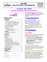
Technical Description
Troubleshooting
TrueDRYDH150usesarefrigerationsystemsimilartoanaircondi-
tioner to remove heat and moisture from incoming air and add heat
totheairthatisdischarged.Hot,high-pressurerefrigerantgasis
routedfromthecompressortothecondensercoil.Therefrigerantis
cooledandcondensedbygivingupitsheattotheairthatisabout
tobedischargedfromtheunit.Therefrigerantliquidthenpasses
throughastrainerandcapillarytubingwhichcausestherefrigerant
pressureandtemperaturetodrop.Itnextenterstheevaporatorcoil
whereitabsorbsheatfromtheincomingairandevaporates.The
evaporatoroperatesinafloodedcondition,whichmeansthatallthe
evaporatortubescontainliquidrefrigerantduringnormaloperation.
Afloodedevaporatorshouldmaintainnearlyconstantpressureand
temperatureacrosstheentirecoil,frominlettooutlet.
Themixtureofgasandliquidrefrigerantentertheaccumulatorafter
leavingtheevaporatorcoil.Theaccumulatorpreventsanyliquid
refrigerantfromreachingthecompressor.Thecompressorevacuatesthecoolrefrigerantgasfromtheaccumulator
and compresses it to a high pressure and temperature to repeat the process.
CONDENSER
EVAPORATOR
CAPILLARY
TUBES
ACCUMULATOR
COMPRESSOR
STRAINER/FILTER
DRIER
M27404

TrueDRY DH150
13 69-2271EFS—01
Problem Recommended Troublshooting Steps
Impellerfandoesnotrunwithfan
switchineitherposition.Impeller
fan does not run with ventilation
timer activated. Compressor runs
brieflybutcycleson&offwith
humiditycontrolturnedtoON.
1. Looseconnectioninimpellerfancircuit.
2. Obstructionpreventsimpellerfanrotation.
3. Defectiveimpellerfan.
4. Defectiveimpellerfanrelay.
5. Defectiveimpellerfancapacitor.
Impellerfanrunswithfanswitch
ON.Impellerfandoesnotrunwith
ventilation timer activated.
1. Defectiveventilationtimer.
2. Timenotcorrectonventilationtimer.
3. Ventilationtimersettomanual&switchedOFF.
4. Defectivefanswitch.
Evaporatorcoilfrostedcontinu-
ously,lowdehumidifyingcapacity.
1. Defrostthermostatlooseordefective.
2. Low refrigerant charge.
3. Dirtyairfilter(s)orairflowrestricted.
4. Excessivelyrestrictiveductingconnectedtounit.
Unitnotprovidingventilation.
Ventilationtimernotoperating
correctly.
1. Iftimerisnotfunctioningcorrectlyresettimerandreprogram.
2. Checkcontrolwireconnections(checkconnectionsatfreshairdamper
also).
3. Defectivefreshairdamper.
4. Defectivefanswitch.
Unitremovessomewater,butnot
asmuchasexpected.
1. Airtemperatureand/orhumidityhavedropped.
2. Humiditymeterandorthermometerusedareoutofcalibration.
3. Unithasentereddefrostcycle.
4. Airfilterdirty.
5. Defectivedefrostthermostat.
6. Low refrigerant charge.
7. Airleaksuchasloosecoverorductingleaks.
8. Defectivecompressor.
9. Restrictiveducting.
10.OptionalCondensatePumpSafetySwitchopen.
Troubleshooting

Installation Guide
69-2271EFS—01 14
Refrigerant Charging
Iftherefrigerantchargeislostduetoserviceoraleak,anewchargemustbeaccuratelyweighedin.Ifanyofthe
oldchargeisleftinthesystem,itmustberecoveredbeforeweighinginthenewcharge.Refertotheunitnameplate
for the correct charge weight and refrigerant type.
Impeller Fan Replacement
Themotorizedimpellerfanisaunitaryassemblyconsistingofthemotorandimpellerfan.Ifdefective,thecomplete
assemblymustbereplaced.
1. Unplugthepowercord.
2. Removethecabinetaccesspanel.
3. Removethescrewattachingtheimpellerfansupportbrackettothebase.
4. Disconnecttheimpellerfanleadsinsidetheelectricbox.
5. Removefan/bracketassemblybyremoving3screwsfromthebracketandinletringassembly.
6. Removethedefectiveimpellerfanfromthebracketandreplacewithitwiththenewimpellerfan.
7. Reassemblethenewimpellerfanbyreversingtheaboveprocedure.Note:Therearetwopinsonthebacksideof
thecabinetthatmustalignwiththetwoholesintheimpellerfansupportbracket.
Compressor/Capacitor Replacement
Thiscompressorisequippedwithatwoterminalexternaloverloadandaruncapacitor,butnostartcapacitoror
relay
Checking Compressor Motor Circuits
Performthefollowingtestsiftheimpellerfanrunsbutthecompressordoesnotwiththefanswitchandventilation
timerOFFandthehumiditycontrolON.
1. Unplugtheunit;removethecabinetsideandtheelectricalconnectioncoveronthecompressortop.
2. PlugintheunitandturnthehumiditycontroltoON.Checkfor110voltsfromcompressorterminalRto
overloadterminal3usinganACvoltmeter.Ifvoltageispresent,gotostep3.Ifnovoltage,theremaybealoose
connectioninthecompressorcircuit.Testeachcomponentforcontinuity.Seetheappropriatesectionifadefect
is suspected.
3. Unplugtheunit,andthendisconnecttheredandyellowwiresfromcompressorterminalsR&S.Usingan
ohmmetercheckcontinuitybetweenthepointslistedbelow.
4. CompressorterminalsCandS:Nocontinuityindicatesanopenstartwinding.Thecompressormustbe
replaced.Normalstartwindingresistanceis3to7ohms.
5. CompressorterminalsCandR:Nocontinuityindicatesanopenrunwinding.Thecompressormustbereplaced.
Normalrunwindingresistanceis.5to2ohms.
6. CompressorterminalCandoverloadterminal1:Nocontinuityindicatesadefectiveoverloadlead.
7. Overloadterminals1and3:Ifthereisnocontinuity,theoverloadmaybetripped.Wait10minutesandtryagain.
Ifthereisstillnocontinuity,itisdefectiveandmustbereplaced.
8. CompressorterminalCandcompressorcase:Continuityindicatesagroundedmotor.Thecompressormustbe
replaced.
9. Disconnectthewiresfromtheruncapacitor.SettheohmmetertotheRx1scale.Thecapacitorisshortedand
mustbereplacedifcontinuityexistsacrossitsterminals.Ifthereisnoneedlemovementwiththemeterseton
theRx100000scale,thecapacitorisopenandmustbereplaced.
10.Reconnectthewirestothecompressorandcapacitor.Pluginandturnontheunit.Ifthecompressorfailsto
start,replacetheruncapacitor.
11.Iftheunitstilldoesnotstart,addingahard-startkit(relay&capacitor)willprovidegreaterstartingtorque.Ifthis
doesn'twork,thecompressorhasaninternalmechanicaldefectandmustbereplaced.
Troubleshooting

TrueDRY DH150
15 69-2271EFS—01
Replacing a Burned Out Compressor
Therefrigerantandoilmixtureinacompressorischemicallyverystableundernormaloperatingconditions.
However,whenanelectricalshortoccursinthecompressormotor,theresultinghightemperaturearccausesapor-
tionoftherefrigerantoilmixturetobreakdownintocarbonaceoussludge,averycorrosiveacid,andwater.These
contaminantsmustbecarefullyremovedotherwiseevensmallresidueswillattackreplacementcompressormotors
and cause failures.
Thefollowingprocedureiseffectiveonlyifthesystemismonitoredafterreplacingthecompressortoinsurethatthe
clean up was complete.
1. Thisprocedureassumesthatthepreviouslylistedcompressormotorcircuittestsrevealedashortedoropen
winding.
2. Removeandproperlydisposeofthesystemcharge.DONOTventtherefrigerantorallowittocontactyoureyes
orskin.
3. Removetheburnedoutcompressor.Userubberglovesifthereisanypossibilityofcontactingtheoilorsludge.
4. Tofacilitatesubsequentsteps,determinethetypeofburnoutthatoccurred.Ifthedischargelineshowsno
evidenceofsludgeandthesuctionlineisalsocleanorperhapshassomelightcarbondeposits,theburnout
occurred while the compressor was not rotating. Contaminants are therefore largely confined to the compressor
housing.Asingleinstallationofliquidandsuctionlinefilter/drierswillprobablycleanupthesystem.
Ifsludgeisevidentinthedischargeline,itwilllikelybefoundinthesuctionline.Thisindicatesthecompressor
burnedoutwillrunning.Sludgeandacidhavebeenpumpedthroughoutthesystem.Severalchangesoftheliquid
andsuctionfilter/drierswillprobablybenecessarytocleansethesystem.
5. Correctthesystemfaultthatcausedtheburnout.Consultthefactoryforadvice.
6. Installthereplacementcompressorwithanewcapacitorandanoversizedliquidlinefilter.
Inarunningburnout,installanoversizedsuctionlinefilter/drierbetweentheaccumulatorandcompressor.
Thoroughlyflushtheaccumulatorwithrefrigeranttoremovealltrappedsludgeandtopreventtheoilholefrom
becomingplugged.Astandingburnoutdoesnotrequireasuctionlinefilter/drier.
7. Evacuatethesystemwithagoodvacuumpumpandaccuratevacuumgauge.Leavethepumponthesystem
for at least an hour.
8. Operatethesystemforashortperiodoftime,monitoringthesuctionpressuretodeterminethatthesuction
filterisnotbecomingplugged.Replacethesuctionfilter/drierifpressuredropoccurs.Ifasevererunningburn
outhasoccurred,severalfilter/driersmayhavetobereplacedtoremovealloftheacidandmoisture.
NOTE:NEVERusethecompressortoevacuatethesystemoranypartofit.
Replacing a Compressor, Non-Burnout
Removetherefrigerantfromthesystem.Replacethecompressorandliquidlinefilter/drier.Chargethesystemto50
PSIGandcheckforleaks.Removethechargeandweighintherefrigerantquantitylistedonthenameplate.Operate
the system to verify performance.
Defrost Thermostat
Thedefrostthermostatisattachedtotherefrigerantsuctiontubebetweentheaccumulatorandthecompressor.It
willautomaticallyshutthecompressoroffifthelowsiderefrigeranttemperaturedropsduetoexcessivefrostfor-
mationontheevaporatorcoil.Theimpellerfanwillcontinuetorun,causingairtoflowthroughtheevaporatorcoil
andmelttheice.Whentheicehasmelted,theevaporatortemperaturewillriseandthethermostatwillrestartthe
compressor.
Troubleshooting

Installation Guide
69-2271EFS—01 16
Parts List
Description Part Number
HeatExchanger 50035445-001
Evaporator 50035445-002
CapillaryTubes.050in.x.124in.x59.00in. 50035445-003
Compressor—Toshiba8.1 50035445-004
Accumulator 50035445-005
Filter/Drier 50035445-006
Tube—Cond.toFilter 50035445-007
Tube—DischargeLine 50035445-008
Condensor 50035445-009
Impeller 50035445-010
Relay/Blower 50035445-011
45mFdCapacitor—Compressor 50035445-012
Transformer 50035445-013
Relay/Compressor 50035445-014
15mFdCapacitor—Impeller 50035445-015
Collar—10in. 50035445-016
Collar—Oval10in.x4in. 50035445-017
Collar 6 in. with damper 50035445-018
Leveling Foot 50035445-019
FilterMERVII 50035445-020
TRANSFORMER
RELAY
COMPRESSOR
HEAT
EXCHANGER
CONDENSOR
EVAPORATOR
CAPACITOR
COMPRESSOR
FILTER DRIER
DISCHARGE
TUBE
ACCUMULATOR
CAPILLARY
TUBES
M27801
TUBE COND.
TO FILTER
TUBE
DISCHARGE
LINE
COLLAR OVAL
10 INCH
LEVELING
FOOT
IMPELLER
RELAY/
BLOWER
CAPACITOR
IMPELLER

TrueDRY DH150
17 69-2271EFS—01
Honeywellwarrantsthisproducttobefreefromdefectsintheworkmanshipormaterials,undernormaluseand
service,foraperiodoffive(5)yearsfromthedateofpurchasebytheconsumer.Ifatanytimeduringthewarranty
periodtheproductisdeterminedtobedefectiveormalfunctions,Honeywellshallrepairorreplaceit(atHoneywell’s
option).
Iftheproductisdefective,
(i)returnit,withabillofsaleorotherdatedproofofpurchase,totheplacefromwhichyoupurchasedit;or
(ii)callHoneywellCustomerCareat1-800-468-1502.CustomerCarewillmakethedeterminationwhethertheprod-
uctshouldbereturnedtothefollowingaddress:HoneywellReturnGoods,Dock4MN10-3860,1885DouglasDr.N.,
GoldenValley,MN55422,orwhetherareplacementproductcanbesenttoyou.
Thiswarrantydoesnotcoverremovalorreinstallationcosts.Thiswarrantyshallnotapplyifitisshownby
Honeywellthatthedefectormalfunctionwascausedbydamagewhichoccurredwhiletheproductwasinthepos-
session of a consumer.
Honeywell’ssoleresponsibilityshallbetorepairorreplacetheproductwithinthetermsstatedabove.HONEYWELL
SHALLNOTBELIABLEFORANYLOSSORDAMAGEOFANYKIND,INCLUDINGANYINCIDENTALOR
CONSEQUENTIALDAMAGESRESULTING,DIRECTLYORINDIRECTLY,FROMANYBREACHOFANYWARRANTY,
EXPRESSORIMPLIED,ORANYOTHERFAILUREOFTHISPRODUCT.Somestatesdonotallowtheexclusionor
limitationofincidentalorconsequentialdamages,sothislimitationmaynotapplytoyou.
THISWARRANTYISTHEONLYEXPRESSWARRANTYHONEYWELLMAKESONTHISPRODUCT.THEDURATION
OFANYIMPLIEDWARRANTIES,INCLUDINGTHEWARRANTIESOFMERCHANTABILITYANDFITNESSFORA
PARTICULARPURPOSE,ISHEREBYLIMITEDTOTHEFIVE-YEARDURATIONOFTHISWARRANTY.Somestates
donotallowlimitationsonhowlonganimpliedwarrantylasts,sotheabovelimitationmaynotapplytoyou.
Thiswarrantygivesyouspecificlegalrights,andyoumayhaveotherrightswhichvaryfromstatetostate.
Ifyouhaveanyquestionsconcerningthiswarranty,pleasewriteHoneywellCustomerRelations,1985DouglasDr,
GoldenValley,MN55422orcall1-800-468-1502.InCanada,writeRetailProductsON15-02H,HoneywellLimited/
HoneywellLimitée,35DynamicDrive,Toronto,OntarioM1V4Z9.
5-Year Limited Warranty

HoneywellInternationalInc.
1985DouglasDriveNorth
GoldenValley,MN55422
http://yourhome.honeywell.com
Automation and Control Solutions
®U.S.RegisteredTrademark.
©2008HoneywellInternationalInc.
69-2271EFS—01M.S.12-08
Honeywell Limited-Honeywell Limitée
35DynamicDrive
Toronto,OntarioM1V4Z9
PrintedinU.S.A.onrecycled
papercontainingatleast10%
post-consumerpaperfibers.
/