
www.EmersonProcess.com
Instruction Manual
AK Protocol
Communication Option for
MLT 1, MLT 2, MLT 3, MLT 4, MLT 5 and CAT 200
3
rd
Edition 11/2003
Instruction Manual
90003752
11/2003

AK Protocol for MLT 1, 2, 3, 4, 5 & CAT 200 Instruction Manual
90003752
11/2003
Emerson Process Management
GmbH & Co. OHG
Industriestrasse 1
D-63594 Hasselroth
Germany
T +49 (0) 6055 884-0
F +49 (0) 6055 884-209
Internet: www.EmersonProcess.com
ESSENTIAL INSTRUCTIONS
READ THIS PAGE BEFORE PROCEEDING!
Emerson Process Management (Rosemount Analytical) designs, manufactures and tests
its products to meet many national and international standards. Because these instruments
are sophisticated technical products, you MUST properly install, use, and maintain
them to ensure they continue to operate within their normal specifications. The following
instructions MUST be adhered to and integrated into your safety program when installing,
using and maintaining Emerson Process Management (Rosemount Analytical) products.
Failure to follow the proper instructions may cause any one of the following situations to
occur: Loss of life; personal injury; property damage; damage to this instrument; and warranty
invalidation.
• Read all instructions prior to installing, operating, and servicing the product.
• If you do not understand any of the instructions, contact your Emerson Process
Management (Rosemount Analytical) representative for clarification.
• Follow all warnings, cautions, and instructions marked on and supplied with the product.
• Inform and educate your personnel in the proper installation, operation, and
maintenance of the product.
• Install your equipment as specified in the Installation Instructions of the appropriate
Instruction Manual and per applicable local and national codes. Connect all products
to the proper electrical and pressure sources.
• To ensure proper performance, use qualified personnel to install, operate, update, program,
and maintain the product.
• When replacement parts are required, ensure that qualified people use replacement parts
specified by Emerson Process Management (Rosemount Analytical). Unauthorized parts
and procedures can affect the product’s performance, place the safe operation of your
process at risk, and VOID YOUR WARRANTY. Look-alike substitutions may result in fire,
electrical hazards, or improper operation.
• Ensure that all equipment doors are closed and protective covers are in place, except
when maintenance is being performed by qualified persons, to prevent electrical
shock and personal injury.
The information contained in this document is subject to change without notice. Misprints
reserved.
1
st
Edition 10/1998 2
nd
Edition 11/2001
3
rd
Edition 11/2003
©
2003 by Emerson Process Management

90003752(2) [AK-Commands] 11/01
AK
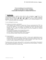
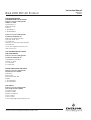
Contents
I)
V24/RS232/485 Interface – Basics 1 - 1
1 Introduction.................................................................................................1 - 1
2 Hardware....................................................................................................1 - 2
3 Protocol settings.........................................................................................1 - 3
3.1 Command telegram .............................................................................1 - 3
3.2 Response telegram..............................................................................1 - 4
3.3 Command telegram for RS485 BUS operating....................................1 - 5
3.4 Response telegram for RS485 BUS operating.....................................1 - 6
4 Specifications of data settings ....................................................................1 - 7
4.1 Head telegram (Header) ......................................................................1 - 7
4.2 Data block and error status byte..........................................................1 - 8
4.3 End of telegram....................................................................................1 - 9
4.4 Command and response telegram timing............................................1 - 10
4.5 Handling of malfunctions......................................................................1 - 10
5 Examples for potential responses to control or write commands resp.
to command telegrams with data (format) errors........................................1 - 11
6 Function sequence and error status after the receipt of the
"SRES" or "STBY" commands....................................................................1 - 19
II) V24/RS232/485 Interface – Single Analyzers and Systems 2 - 1
1 Basic Informations......................................................................................2 - 2
2 List of all Codes [Commands - Overview including page numbers]......2 - 5
2.1 Control commands...............................................................................2 - 5
2.2 Read commands..................................................................................2 - 6
2.3 Write commands..................................................................................2 - 7
3 Description of all Control Commands .........................................................2 - 8
4 Description of all Read Commands ............................................................2 - 39
5 Description of all Write Commands.............................................................2 - 85
Supplement
1 Overview about working AK commands in NGA devices ..........Supplement - 1
2 AK Service Commands..............................................................Supplement - 3

AK
90003752(1) [AK-Commands] 10/98

I) V24/RS232/485-Interface - Basics
90003752(2) [AK-Commands] 11/01
AK
1 - 1
Protocol settings of a serial interface
between a test bench control computer
and peripheral analyzers on exhaust test benches
1. Introduction
The serial interface is made for slow point to point connections (f ≤ 10 Hz). The
communication between the test bench control computer (TBCC) and the peripheral
analyzers works according to the master slave principle. That means that the peripheral
analyzers will only answer with a response telegram to the command telegram of the
TBCC. They will not send an own message.
You can distinguish two cases:
(1) Analyzers in a function unit (system)
Some analyzers are combined to a logical unit. They are connected to the TBCC via
an front-end computer. In that case the communication will not take place directly
between the TBCC and the analyzers, but between the TBCC and the front-end
computer. Each analyzer or the whole system unit will be identified by a defined
channel number:
K0 is the channel number for the whole defined system.
("Assembling command resp. assembling report")
Kn (n=1, nmax) is the channel number for each analyzer.
KV is the channel number for the front-end computer.
(2) Single analyzers
Each analyzer is connected directly to the TBCC. In that case the identification of each
analyzer will be done by the hardware connections and not by a software control. That
is why the two channel number bytes (Kn) could be deleted. But in spite of that the
channel number is generally 0 (K0) to get a uniform protocol.
The data transfer will only be done by ASCII code to get an easy handling of the protocol
with a terminal for simulation of the TBCC, the system unit and the analyzers. Therefore,
no parity check will be done as data saving.

1 - 2
AK
90003752(2) [AK-Commands] 10/01
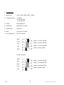
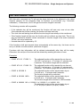
2. Hardware
1. Baud rate: 1200, 2400, 4800, 9600, 19200
2. Length of signs: 1 start bit
7 or 8 data bits
1 or 2 stop bits
3. Parity: even/odd/none
4. Operating: full duplex, no echo
5. Handshake: Xon/Xoff
6. Plug: 9 pin sub d, socket
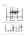
7. Pin assignment: RS 232 module
RS 485 module
GND
Rxd
TxD
NC
GND
GND
RxD-
RxD+
TxD+
TxD-
Relay 1 contact NC/NO
Relay 2 contact NC/NO
Relay 3 contact NC/NO
Relay common node
Relay 1 contact NC/NO
Relay 2 contact NC/NO
Relay 3 contact NC/NO
Relay common node

I) V24/RS232/485-Interface - Basics
90003752(2) [AK-Commands] 11/01
AK
1 - 3
3. Protocol settings
The data and command transfer protocol has the following structure:
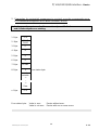
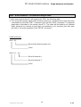
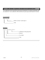
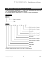
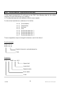
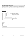
3.1. Command telegram
1. Byte STX
2. Byte DON'T CARE
3. Byte FUNCT. CODE 1
4. Byte FUNCT. CODE 2 HEAD
5. Byte FUNCT. CODE 3
6. Byte FUNCT. CODE 4
7. Byte BLANK
8. Byte "K" VARIABLE DATA
9. Byte NUMBER
(number with several
digits possible)
D
A (other data
T can also disappear,
A depending on the
function code)
n. Byte ETX END

1 - 4
AK
90003752(2) [AK-Commands] 10/01
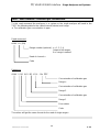
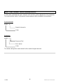
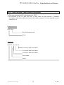
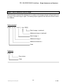
3.2. Response telegram
1. Byte STX
2. Byte DON'T CARE
3. Byte FUNCT. CODE 1
4. Byte FUNCT. CODE 2 HEAD
5. Byte FUNCT. CODE 3
6. Byte FUNCT. CODE 4
7. Byte BLANK
8. Byte ERROR STATUS
FIXED
DATA
D
A VARIABLE DATA
T (can also disappear,
A depending on the
function code)
n. Byte ETX END

I) V24/RS232/485-Interface - Basics
90003752(2) [AK-Commands] 11/01
AK
1 - 5
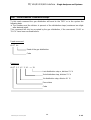
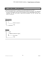
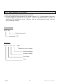
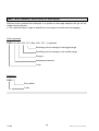
3.3. Command telegram for RS485 BUS operating
1. Byte STX
2. Byte BUS ADDRESS
3. Byte FUNCT. CODE 1
4. Byte FUNCT. CODE 2 HEAD
5. Byte FUNCT. CODE 3
6. Byte FUNCT. CODE 4
7. Byte BLANK
8. Byte "K" VARIABLE DATA
9. Byte NUMBER
(Number with several
digits possible)
D
A (other data
T can also disappear,
A depending on the
function code)
n. Byte ETX END

1 - 6
AK
90003752(2) [AK-Commands] 10/01
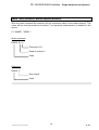
3.4. Response telegram for RS485 BUS operating
1. Byte STX
2. Byte BUS ADDRESS
3. Byte FUNCT. CODE 1
4. Byte FUNCT. CODE 2 HEAD
5. Byte FUNCT. CODE 3
6. Byte FUNCT. CODE 4
7. Byte BLANK
8. Byte ERROR STATUS
FIXED
DATA
D
A VARIABLE DATA
T (can also disappear,
A depending on the
function code)
n. Byte ETX END

I) V24/RS232/485-Interface - Basics
90003752(2) [AK-Commands] 11/01
AK
1 - 7
4. Specifications of data settings
4.1. Head telegram (Header)
The begin of each transfer is a "STX" in the first byte. Each "STX" will start a new transfer.
Previous transfers will be deleted, if they are not finished by "ETX". That means, only
completed telegrams may be interpreted and answered.
You can take any content for the "DON'T CARE" byte, excluding control signs or signs
reserved by the AK commands.
For the RS485 BUS operating an address byte will be used instead of the "DON'T CARE"
byte. The analyzers will only answer to this command if the bus address setup will concur
with this byte.
In the command telegram a function code will be sent to the system unit or the analyzer
with the four function bytes.
In the response telegram this function code will be sent back as an echo if the transfer is
successful. The echo will be four question marks (????), if
• the command telegram has not minimum the number of bytes of the head telegram, the
channel number in the data part and the end telegram (number of bytes = 10; using a
channel number with two digits = 11 bytes) or
• the function code has errors or is unknown.
The function code may not contain blanks.
There are three groups of function codes:
(1) Control commands
(2) Read commands
(3) Write commands

1 - 8
AK
90003752(2) [AK-Commands] 10/01
4.2. Data block and error status byte
The data presentation is variable. A fixed format will not be used. A blank or a <CR> with
<LF> will be used as separating characters of data. The separation with <CR><LF> will
only be done, if the following complete date will have more than 60 digits. Each data set
will begin normally with a blank.
The data block of the command telegram has only variable data. These data depend on
the function code. They can disappear for some function codes excluding the channel
number. The channel number can have more than two bytes.
The data block of the response telegram is divided in fixed and variable data. The first digit
of the fixed data is a blank followed by an error status byte. The error status number will be
zero for an error free running analyzer or system unit. The error status number will be
counted up from 1 to 9 with each change in the error status. The error status number will
be zero again after the errors will be removed. Changing the status of the system will not
change the error status number. The variable data depend on the function code. They can
disappear for some function codes.
The long and variable floating point format or the E- Format are allowed to display the
digits of numbers. You can find in each analyzer protocol which of these formats may be
used. The decimal point can disappear for integers. The "+/-" sign may only be used for
negative numbers. Digits without physical meaning have to be vanished.
You can distinguish the following cases if a date with an error exists for a reading:
(1) The transfer of the date is not possible, e.g. an analyzer in a system is missing or it
cannot send a signal.
→ The date will be replaced by a "#".
(2) The date is only valid with restrictions, e.g. FID temperature too low.
→ The date will begin with a "#".
Range overflow and range underflow will be displayed in the same way. "Valid" means
that no criterions of plausibility will be considered.
Example:
You ask for a concentration value and the analyzer is in the "stand-by" mode. The date
must not be marked with "#" as "valid with restrictions", if the analyzer would work
normally in the operation mode.

I) V24/RS232/485-Interface - Basics
90003752(2) [AK-Commands] 11/01
AK
1 - 9
If an analyzer or a system is not in the "REMOTE" status, the control and write commands
have to report "OF" ("Offline") in the data set to the. In system units the channel number
has to be reported, too.
If one analyzer is missing, a system unit has to send the channel number and "NA" ("Not
Available") to the test bench control computer with control and write commands.
A response telegram is not possible, if the test bench control computer has a direct contact
to the analyzers and one analyzer is missing or the whole system is missing. So the test
bench control computer has to realize the missing of devices by "Time Out".
If the system or the analyzer is occupied by executing a function, the new start of a control
command will lead to the response "BS" (Busy) in the data block of the response telegram.
The running function will not be disturbed. Exception: The order was a software reset.
If the data or parameters transfer is not complete (i.e. not expected format) in the
command telegram to the system or the analyzer, the test bench control computer will get
a "SE" (Syntax Error) in the data block of the following response telegram.
If the system or the analyzers cannot work with the data or the parameters of the
command telegram (data error, parameter error), the test bench control computer will get a
"DF" (data error) in the data block of the following response telegram.
4.3. End of telegram
Each transfer will end with "ETX" in the last byte.

1 - 10
AK
90003752(2) [AK-Commands] 10/01
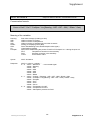
4.4. Command and response telegram timing
For each command telegram of the TBCC the peripheral analyzer sends a response
telegram.
It is not allowed for the TBCC to send new command telegrams before this response
telegram is received.
For most of the command telegrams this response might be sent after some milliseconds.
But for some commands the response telegram might be started to sent 2-3 seconds after
receiving the command telegram. The time starts the moment the peripheral analyzer
receives the ETX character of the command telegram.
It is not assured that the response telegram is sent without any delay between the single
characters but it might be that there are up to 2-3 seconds in between.
4.5. Handling of malfunctions
For the case of a malfunction it might be that the ETX-character of the command telegram
is not received by the peripheral analyzer. Then it will not evaluate the command telegram
and so will not send a response telegram.
In this case it is in the responsibility of the TBCC not to run into an endless loop. It has to
have a timeout of 4-5 seconds to react on this communication failure.
The TBCC may repeat the last command telegram or doing some other exception
handling.

I) V24/RS232/485-Interface - Basics
90003752(2) [AK-Commands] 11/01
AK
1 - 11
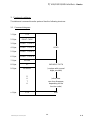
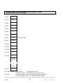
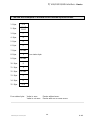
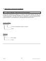
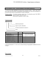
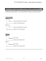
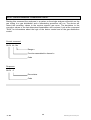
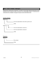
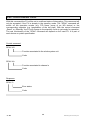
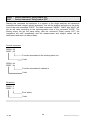
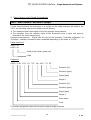
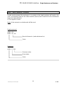
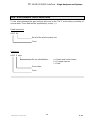
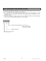
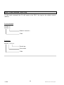
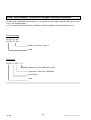
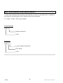
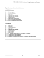
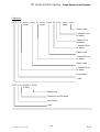
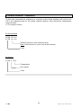
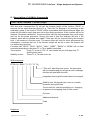
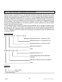
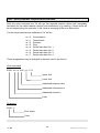
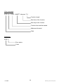
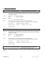
5. Examples for potential responses to control or write commands resp.
to command telegrams with data (format) errors:
1. Analyzer and/or system unit with several analyzers "Online"
and called analyzers are existing.
1. Byte STX
2. Byte
DON'T
CARE
3. Byte C
4. Byte O
5. Byte D
6. Byte E
7. Byte BLANK
8. Byte x Error status byte
evtl.
variable
...
.
...
Data
n. Byte ETX
Error status byte: Value is zero: Device without error.
Value is not zero: Device with one or more errors.

1 - 12
AK
90003752(2) [AK-Commands] 10/01
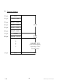
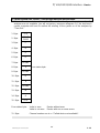
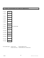
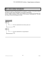
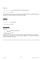
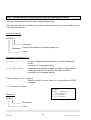
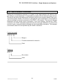
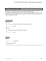
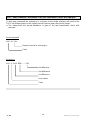
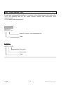
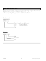
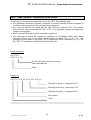
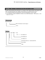
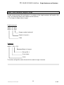
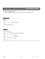
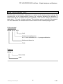
2. Analyzer and/or system unit with several analyzers "Offline"
and called analyzers are existing.
1. Byte STX
2. Byte
DON'T
CARE
3. Byte C
4. Byte O
5. Byte D
6. Byte E
7. Byte BLANK
8. Byte x Error status byte
9. Byte BLANK
10. Byte K
11. Byte n
12. Byte BLANK
13. Byte O
14. Byte F
evtl.
variable
...
.
...
Data
n. Byte ETX
Error status byte: Value is zero: Device without error.
Value is not zero: Device with one or more errors.
11. Byte: Channel number is zero: "The whole system unit offline".
Channel number is one to n: "Single analyzer offline".

I) V24/RS232/485-Interface - Basics
90003752(2) [AK-Commands] 11/01
AK
1 - 13
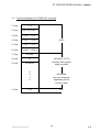
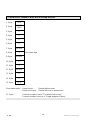
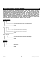
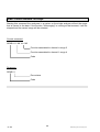
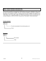
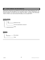
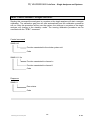
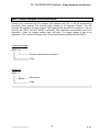
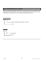
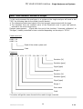
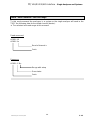
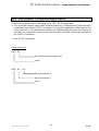
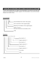
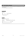
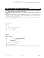
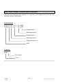
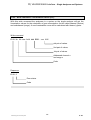
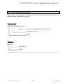
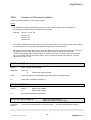
3. Called system unit "online", called single analyzer not available.
If the test bench control computer will call the devices directly and the system unit or the
analyzer are not available, you will not get any response telegram. So, the test bench
control computer will have to realize the missing of the system or of the analyzer by
"Time Out".
1. Byte STX
2. Byte
DON'T
CARE
3. Byte C
4. Byte O
5. Byte D
6. Byte E
7. Byte BLANK
8. Byte x Error status byte
9. Byte BLANK
10. Byte K
11. Byte n
12. Byte BLANK
13. Byte N
14. Byte A
15. Byte ETX
Error status byte: Value is zero: Device without error
Value is not zero: Device with one or more errors
11. Byte: Channel number one to n: "Called device not available".

1 - 14
AK
90003752(2) [AK-Commands] 10/01
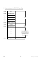
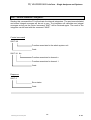
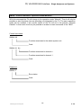
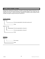
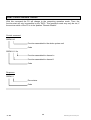
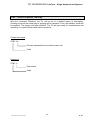
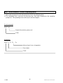
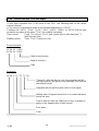
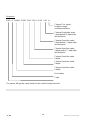
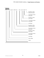
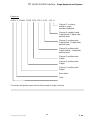
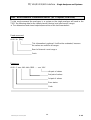
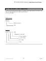
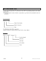
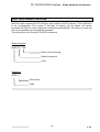
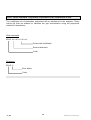
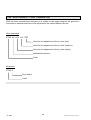
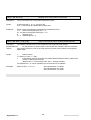
4. Called system unit "offline", called single analyzer not available.
If the test bench control computer will call the devices directly and the system unit or the
analyzer are not available, you will not get any response telegram. So, the test bench
control computer will have to realize the missing of the system or of the analyzer by
"Time Out".
1. Byte STX
2. Byte
DON'T
CARE
3. Byte C
4. Byte O
5. Byte D
6. Byte E
7. Byte BLANK
8. Byte x Error status byte
9. Byte BLANK
10. Byte K
11. Byte 0
12. Byte BLANK
13. Byte O
14. Byte F
15. Byte BLANK
16. Byte K
17. Byte n
18. Byte BLANK
19. Byte N
20. Byte A
21. Byte ETX

I) V24/RS232/485-Interface - Basics
90003752(2) [AK-Commands] 11/01
AK
1 - 15
Error status byte: Value is zero: Device without error.
Value is not zero: Device with one or more errors.
11. Byte: Channel number zero: "System unit offline"
17. Byte: Channel number one to n: "Called device not available.

1 - 16
AK
90003752(2) [AK-Commands] 10/01
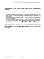
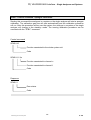
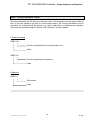
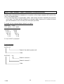
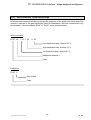
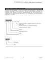
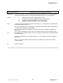
5. Called unit or channel is busy with a running function.
1. Byte STX
2. Byte
DON'T
CARE
3. Byte C
4. Byte O
5. Byte D
6. Byte E
7. Byte BLANK
8. Byte x Error status byte
9. Byte BLANK
10. Byte K
11. Byte n
12. Byte BLANK
13. Byte B
14. Byte S
15. Byte ETX
Error status byte: Value is zero: Device without error.
Value is not zero: Device with one or more errors.
11. Byte: Channel number is zero: "The whole unit is busy".
Channel number is one to n: "Single analyzer is busy".
Page is loading ...
Page is loading ...
Page is loading ...
Page is loading ...
Page is loading ...
Page is loading ...
Page is loading ...
Page is loading ...
Page is loading ...
Page is loading ...
Page is loading ...
Page is loading ...
Page is loading ...
Page is loading ...
Page is loading ...
Page is loading ...
Page is loading ...
Page is loading ...
Page is loading ...
Page is loading ...
Page is loading ...
Page is loading ...
Page is loading ...
Page is loading ...
Page is loading ...
Page is loading ...
Page is loading ...
Page is loading ...
Page is loading ...
Page is loading ...
Page is loading ...
Page is loading ...
Page is loading ...
Page is loading ...
Page is loading ...
Page is loading ...
Page is loading ...
Page is loading ...
Page is loading ...
Page is loading ...
Page is loading ...
Page is loading ...
Page is loading ...
Page is loading ...
Page is loading ...
Page is loading ...
Page is loading ...
Page is loading ...
Page is loading ...
Page is loading ...
Page is loading ...
Page is loading ...
Page is loading ...
Page is loading ...
Page is loading ...
Page is loading ...
Page is loading ...
Page is loading ...
Page is loading ...
Page is loading ...
Page is loading ...
Page is loading ...
Page is loading ...
Page is loading ...
Page is loading ...
Page is loading ...
Page is loading ...
Page is loading ...
Page is loading ...
Page is loading ...
Page is loading ...
Page is loading ...
Page is loading ...
Page is loading ...
Page is loading ...
Page is loading ...
Page is loading ...
Page is loading ...
Page is loading ...
Page is loading ...
Page is loading ...
Page is loading ...
Page is loading ...
Page is loading ...
Page is loading ...
Page is loading ...
Page is loading ...
Page is loading ...
Page is loading ...
Page is loading ...
Page is loading ...
Page is loading ...
Page is loading ...
Page is loading ...
Page is loading ...
Page is loading ...
Page is loading ...
Page is loading ...
Page is loading ...
Page is loading ...
Page is loading ...
Page is loading ...
Page is loading ...
Page is loading ...
Page is loading ...
Page is loading ...
Page is loading ...
Page is loading ...
Page is loading ...
Page is loading ...
Page is loading ...
Page is loading ...
Page is loading ...
Page is loading ...
Page is loading ...
Page is loading ...
Page is loading ...
Page is loading ...
Page is loading ...
Page is loading ...
-
 1
1
-
 2
2
-
 3
3
-
 4
4
-
 5
5
-
 6
6
-
 7
7
-
 8
8
-
 9
9
-
 10
10
-
 11
11
-
 12
12
-
 13
13
-
 14
14
-
 15
15
-
 16
16
-
 17
17
-
 18
18
-
 19
19
-
 20
20
-
 21
21
-
 22
22
-
 23
23
-
 24
24
-
 25
25
-
 26
26
-
 27
27
-
 28
28
-
 29
29
-
 30
30
-
 31
31
-
 32
32
-
 33
33
-
 34
34
-
 35
35
-
 36
36
-
 37
37
-
 38
38
-
 39
39
-
 40
40
-
 41
41
-
 42
42
-
 43
43
-
 44
44
-
 45
45
-
 46
46
-
 47
47
-
 48
48
-
 49
49
-
 50
50
-
 51
51
-
 52
52
-
 53
53
-
 54
54
-
 55
55
-
 56
56
-
 57
57
-
 58
58
-
 59
59
-
 60
60
-
 61
61
-
 62
62
-
 63
63
-
 64
64
-
 65
65
-
 66
66
-
 67
67
-
 68
68
-
 69
69
-
 70
70
-
 71
71
-
 72
72
-
 73
73
-
 74
74
-
 75
75
-
 76
76
-
 77
77
-
 78
78
-
 79
79
-
 80
80
-
 81
81
-
 82
82
-
 83
83
-
 84
84
-
 85
85
-
 86
86
-
 87
87
-
 88
88
-
 89
89
-
 90
90
-
 91
91
-
 92
92
-
 93
93
-
 94
94
-
 95
95
-
 96
96
-
 97
97
-
 98
98
-
 99
99
-
 100
100
-
 101
101
-
 102
102
-
 103
103
-
 104
104
-
 105
105
-
 106
106
-
 107
107
-
 108
108
-
 109
109
-
 110
110
-
 111
111
-
 112
112
-
 113
113
-
 114
114
-
 115
115
-
 116
116
-
 117
117
-
 118
118
-
 119
119
-
 120
120
-
 121
121
-
 122
122
-
 123
123
-
 124
124
-
 125
125
-
 126
126
-
 127
127
-
 128
128
-
 129
129
-
 130
130
-
 131
131
-
 132
132
-
 133
133
-
 134
134
-
 135
135
-
 136
136
-
 137
137
-
 138
138
-
 139
139
-
 140
140


Emerson Process Management MLT 1 User manual
- Type
- User manual
- This manual is also suitable for
Ask a question and I''ll find the answer in the document
Finding information in a document is now easier with AI
Related papers
Other documents
-
Emerson NGA 2000 User manual
-
-
Geovision GV-NETCARD3.1 Datasheet
-
Rosemount MLT 2 LON Owner's manual
-
Niles SSVC-2 User manual
-
-
Kyosho KFB003 KF01 T90-TYPE3 BodySet User manual
-
-
-