Broan DF6SF Installation guide

Category
Stoves
Type
Installation guide

This manual is also suitable for

Installation Instructions
Do not store or use gasoline or other
ammable vapors and liquids in the
vicinity of this or any other appliance.
Do not use this furnace if any part has
been under water. A fl ood-damaged fur-
nace is extremely dangerous. Attempts
to use the furnace can result in fi re or
explosion. A qualifi ed service agency
should be contacted to inspect the
furnace and to replace all gas controls,
control system parts, electrical parts
that have been wet or the furnace if
deemed necessary.
DO NOT DESTROY. PLEASE READ CAREFULLY AND KEEP IN A SAFE PLACE FOR FUTURE REFERENCE.
Improper installation,
adjustment, alteration,
service, or maintenance
can cause injury or prop-
erty damage. Refer to this
manual, for assistance
or additional information
consult a qualifi ed installer,
service agency, or the gas
supplier.
These instructions are primarily intended to assist qualifi ed individuals experienced in the proper installation of this
appliance. Some local codes require licensed installation/service personnel for this type of equipment. Read all instruc-
tions carefully before starting the installation.
FOR YOUR SAFETY
WHAT TO DO
IF YOU SMELL GAS
Do not try to light any
appliance.
Do not touch any elec-
trical switch; do not
use any phone in your
building.
Immediately call your
gas supplier from a
neighbor’s phone. Fol-
low the gas supplier’s
instructions.
If you cannot reach your
gas supplier, call the fi re
department.
Extinguish any open
ame.
FOR YOUR SAFETY
WARNING:
!
14/15 SEER Dual Fuel Heating and Cooling Packaged System
2
TABLE OF CONTENTS
Table of Contents
Section 1. Owner Information ..................................................................................................3
Operating Instructions .............................................................................................................4
Specifi cations ...........................................................................................................................4
Safety Considerations ..............................................................................................................5
Installation Requirements ........................................................................................................5
Unit Installation .........................................................................................................................9
Air Supply for Combustion and Ventilation ..........................................................................10
Circulating Air Supply ............................................................................................................10
Air Ducts ..................................................................................................................................10
Gas Supply and Piping ..........................................................................................................11
Gas and High Altitude Conversions .....................................................................................13
Electrical Wiring ......................................................................................................................13
Low Voltage Wiring .................................................................................................................14
Variable Speed Blower ...........................................................................................................15
Optional Humidistat ...............................................................................................................16
Start Up and System Check ...................................................................................................17
Component Functions ...........................................................................................................21
Unit Maintenance ....................................................................................................................22
Sequence of Operation ..........................................................................................................24
Wiring Diagrams ................................................................................................................26-29
Charging Charts ................................................................................................................30-31
Installation/Performance Check List .....................................................................................32
3
It is the sole responsibility of the homeowner to make
certain that heat pump has been correctly set up and
adjusted to operate properly.
The Manufacturer warranty on the heat pump covers
defects in material or workmanship for the warranty pe-
riod. The manufacturer is not responsible for any costs
resulting from problems due to improper setup, improper
installation, adjustments, improper operating procedure
on the part of the user, etc.
Some specifi c examples of service calls which are not
included in the limited warranty are:
1. Correcting wiring problems in the electrical circuit
supplying the heat pump.
SECTION 1. OWNER INFORMATION
WINTER HEATING
1. Outdoor air enters the heat pump.
2. The cold, heat-transfer section (outdoor coil) extracts
the heat from the air as the refrigerant evaporates from
a liquid to a cold gas.
3. The refrigerant, compressed to a hot gas by the heat
pump, carries the heat to the heat-transfer section
(indoor coil).
4. The hot, heat-transfer section (indoor coil) releases
the heat as the refrigerant condenses from a gas to a
liquid.
5. The blower circulates the heat throughout the home
via the supply duct.
6. The refrigerant returns to the outdoor coil and evaporates
once again to absorb more heat.
SUMMER COOLING
1. Indoor air enters the return air duct.
2. The cold, heat-transfer section (indoor coil) extracts the
heat from the air as the refrigerant evaporates from a
liquid to a cold gas.
3. The refrigerant, drawn to the heat pump and compressed
to a hot gas, carries the heat outdoors.
4. The hot, heat-transfer section (outdoor coil) releases
the heat as the refrigerant condenses from a gas to a
liquid.
5. The heat pump (outdoor fan) discharges the heat to
the outside air.
6. The refrigerant returns to the indoor coil and evaporates
once again to absorb more heat.
2. Resetting circuit breakers or other switches.
3. Adjusting or calibrating of thermostat.
To avoid misunderstandings at a later date, carefully
review these responsibilities with your dealer or service
company.
The heat pump system will heat and cool your home and
save your energy dollars.
During the summer, a heat pump cools a house by
absorbing heat from within the house and exhausting it
outdoors. During the winter, a heat pump heats a house
by absorbing heat outdoors and exhausting it indoors.
This is an effi cient heating means because you pay for
“moving” heat from outdoors to indoors, but do not pay
to generate the heat.
5
4
1
2
3
6
2
1
5
3
6
4
Heat Pump Operation
4
OPERATING INSTRUCTIONS
NOTE: A thermostat with fossil fuel back-up heat
capability is required to operate the Dual Fuel
iHybrid™ heat pump system.
To Operate Your Heat Pump For Cooling —
1. Set the thermostat system mode to COOL and the
thermostat fan mode to AUTO. See Figure 1.
2. Set the thermostat temperature selector to the desired
cooling temperature. The outdoor unit fan, the indoor
blower, and the compressor will all cycle on and off to
maintain the indoor temperature at the desired cooling
level.
To Operate Your Heat Pump For Heating —
1. Set the thermostat system mode for HEAT and the
thermostat fan mode to AUTO. See Figure 1.
2. Set the thermostat temperature selector to the desired
heating temperature. The outdoor unit fan, the indoor
blower, and the compressor will all cycle on and off to
maintain the indoor temperature at the desired heating
level.
Emergency Heat — Your thermostat will include a sys-
tem switch position termed EM HT or AUX HT, etc. With
the system mode set to EM HT, etc., the compressor
and outdoor fan will be locked off and the secondary
gas furnace will be used as a source of heat. Sustained
use of gas heat in place of the heat pump will result in
an increase in electric utility costs.
Defrost — During cold weather heating operation, the
outdoor until will develop a coating of snow and ice on
the heat transfer coil. This is normal and the unit will
periodically defrost itself. During the defrost cycle, the
outdoor fan will stop, while the compressor continues to
run and heat the outdoor coil, causing the snow and ice to
melt. During defrost, there may be some steam rise from
the outdoor unit as the warm coil causes some melted
frost to evaporate.
SPECIFICATIONS
Single Package Dual Fuel iHybrid™ Heating and Cooling
Systems are designed for outdoor rooftop or ground level
slab installations. The units are shipped ready for horizontal
duct connections and are easily converted for down fl ow
applications.
All models are shipped from the factory with the
following:
1. Variable speed direct-drive blower.
2. 2-Stage compressor.
3. Demand defrost board.
4. Horizontal or Down fl ow duct connections.
The unit dimensions are shown in Figure 2.
The Dual Fuel iHybrid™ package heat pump comes
with a factory installed gas furnace for secondary heat.
A thermostat with fossil fuel back-up heat capability is
required with this system. This feature insures that the
compressor is off before the secondary heat is initiated.
Figure 1. Typical Thermostat
System
Mode
Fan
Mode
Temperature
Selector
5
SAFETY CONSIDERATIONS
It is the responsibility of the installer to ensure that the
installation is made in accordance with all applicable local
and national codes.
WARNING:
Improper installation, service, adjustment,
or maintenance may cause explosion, re,
electrical shock or other hazardous conditions
which may result in personal injury or property
damage. Unless otherwise noted in these
instructions, only factory authorized kits or
accessories may be used with this product.
Noncompliance may void the unit’s warranty.
Labels, Tags When working with this equipment, follow
all precautions in the literature, on tags, and on labels
provided with the unit and/or approved fi eld installed kits.
The type of hazard and severity are described on each
label or tag.
Pressures Within The System — This equipment
contains liquid and gaseous refrigerant under high
pressure. Installation or servicing should only be performed
by qualifi ed trained personnel thoroughly familiar with this
type equipment.
CAUTION:
This unit uses refrigerant R-410A. DO NOT under
any circumstances use any other refrigerant
besides R-410A in this unit. Use of another
refrigerant will damage this unit.
INSTALLATION REQUIREMENTS
Equipment Check — Before beginning the installation,
verify that the unit model is correct for the job. The unit
model number is printed on the data label. This furnace
is NOT to be used for temporary heating of buildings or
structures under construction. All units have been securely
packaged at the point of shipment. After unpacking the unit,
carefully inspect it for apparent and concealed damage.
Claims for damage should be fi led with the carrier by the
consignee.
Requirements and Codes — The installer must comply
with all local codes and regulations which govern this type of
equipment. Local codes and regulations take precedence
over any recommendations contained in these instructions.
In the absence of local codes, the installation must conform
with the National Fuel Gas Code (ANSI 2223.1, NFPA-54),
or Canadian installations must conform with CAN/CGA-
B149 installation codes. All electrical wiring must be made
in accordance with codes and regulations and with the
National Electric Code (ANSI/NFPA 70) or in Canada the
Canadian Electric Code Part 1 CSA C.22.1. Air Ducts
must be installed in accordance with the standards of
the National Fire Protection Association “Standards for
Installation of Air Conditioning and Ventilation Systems”
(NFPA 90A), “Standard for Installation of Residence
Type Warm Air Heating and Air Conditioning Systems”
(NFPA 90B), these instructions, and all applicable local
codes.
The National Fuel Gas Code is available by writing:
American National Standards Institute, Inc.
1430 Broadway
New York, NY 10018
NFPA publications are available by writing:
National Fire Protection Association
Batterymarch Park
Quincy, ME 02269
Unit Location — This Dual Fuel iHybrid™ heat pump
is designed only for outdoor installations. Choosing the
location of the unit should be based on minimizing the
length of the supply and return ducts. Consideration
should also be given to availability of electric power,
service access, noise, and shade. Suffi cient clearance
for unobstructed airfl ow through the outdoor coil must be
maintained in order to achieve rated performance See
Figure 4 for minimum clearances to obstructions.
Venting Requirements — This unit has been equipped
with an integral venting system and designed to operate
only with this venting system.
No additional venting shall
be used. This unit must be vented to the outdoors.
WARNING:
Do not vent furnace through a conventional
venting system.
A vent cover assembly has been supplied with the unit.
It can be found secured to the gas controls within the
control area of this unit. Figure 3 shows the proper
installation of the vent cover assembly over the vent outlet
on the exterior of the corner panel. The fasteners used
to secure the vent cover assembly have been included
in the homeowner’s package.
WARNING:
The vent cover assembly must be installed to
assure proper operation of the unit.
6
Top View
Side View
Back View
24 9/10
13 1/2
16
12
13 3/10
13 1/2
16
12
CG
A
47 1/2
3/4" NPT Female
Drain Connector
B
DOWNFLOW
SUPPLY DUCT
OPENING
DOWNFLOW
RETURN DUCT
OPENING
23 1/2
Figure 2. Dimensions
47.5
Electric
Supply Entry
Low Voltage Entry
Gas Supply
Entry
15.75
23.75
29.75
2.9
1.8
4.0
12.45
12.45
4.0
55.8
8.75
Horizontal
Supply Duct
Opening
Horizontal
Return Duct
Opening
4.0
1.75
9.75 24.75
16.0
Condensing
Coil
13.5
13.5
16.0
16.0
C
Model Number
Unit Weight
Center of Gravity
Height (in inches)
C
AB
with base rails without base rails
DF6SF-X24
480 26.0 27.0 39.0 35.3
DF6SF-X36
599 27.0 26.5 43.0 39.3
DF6SF-X48
618 27.0 26.5 47.0 43.3
DF6SE-X60
580 27.0 26.5 43.0 39.3
7
The following list is a summary of the requirements for the
location of the termination of the venting system:
1. The location of the vent termination must be consistent
with the National Fuel Gas Code (ANSI Z223.1) or
CAN/CGA-B149 Installation Codes.
2. The vent termination must be located at least four (4)
feet horizontally from any electric meters, gas meters,
regulators, and relief equipment.
3. The vent termination must be located at least three
(3) feet above any forced air inlet located within ten
(10) feet.
4. The vent termination must be located at least four (4)
feet below, four (4) feet horizontally from, or one (1)
foot above any door, window, or gravity air inlet into
any building.
5. The vent termination must be located at least one (1)
foot above grade.
6. The unit should be installed in such a manner as to
prevent snow accumulation from obstructing the vent
termination.
Figure 4. Minimum Clearances
36”
36”
36”
36”
1”
Corner Panel
of Unit
Vent Cover
Assembly
Figure 3. Vent Assembly
Fastener
Exhaust Duct
Opening
7. The unit installation shall avoid areas where
condensate drainage may cause problems by dropping
on planters or patios, etc. Furthermore, ensure that
the exhaust gases will not impinge on windows or
building surfaces, which may be compromised or
damaged by condensation. Do not install the unit such
that exhaust from the vent termination is directed into
window wells, stairwells, under decks, or in alcoves or
similarly recessed areas. The vent termination must
not be located above any public walkways.
Clearances to Combustible Materials — See Figure 4
for required clearances to combustible materials. Refer to
the unit data label for the model number. The Dual Fuel
iHybrid™ unit is suitable for installation on combustible
ooring or class A, B, or C roofi ng materials. A clearance
of at least 36 inches from the blower access panel and
from the louvered control access panel is recommended to
allow for servicing and maintenance. Where accessibility
to combustibles clearances are greater than minimum
clearances, accessibility clearances must take
preference. Suffi cient clearance for unobstructed airfl ow
through the louvered control access panel and through
the outdoor coil must be maintained in order to achieve
rated performance. See Figure 4 for minimum clearances
to obstructions.
Thermostat — The 14/15 SEER Dual Fuel iHybrid™ Heat
Pump unit uses a special two speed compressor to achieve
a high level of effi ciency in a compact frame. A two stage
cooling/two stage heating 24VAC thermostat can be used
with these units. For the highest effi ciency the use of a
two-stage cooling thermostat is recommended.
8
4. Feed the sensor through the star bushing. Use the
star bushing to secure the mounting bracket to the
unit. (see fi gure 5)
5. Secure the ambient sensor inside the plastic clip and
secure it to the mounting bracket with the screw and
nut provided NOTE: Install one spacer next between
the plastic clip and mounting bracket as shown in
gure 5.
6. Bend the mounting bracket into position. Install the
vent cover screw to the mounting bracket as shown
in fi gure 6.
NOTE: A thermostat with fossil fuel back-up heat
capability is required with this unit.
Air Filter Requirements — A suitable air fi lter system must
be installed in the unit or in the return air system upstream
of the evaporator coil. Refer to Table 1 for recommended
lter sizes. Air fi lter pressure drop must not exceed 0.08
inches WC. This unit is not supplied with air fi lter(s) and
WARNING:
Never operate unit without a fi lter. Failure
to follow this warning could result in a fi re,
personal injury, or death.
has no factory equipped means for accommodating
internal air fi lter(s). For downfl ow installations only, an
internal fi lter accessory kit can be ordered. For horizontal
installations, the air fi lter system must be installed in the
return air ductwork. All return air to this unit must pass
through the fi lter(s) before entering the evaporator coil.
Ambient Sensor Mounting — For optimum performance
of your Dual Fuel iHybrid™ heat pump package system,
the ambient sensor must be mounted outside of the unit.
To mount the ambient sensor:
1. Remove the mounting bracket wire tied to the gas
manifold pipe and all hardware included in the
homeowners packet.
2. Remove star bushing from 7/8” hole in corner panel
of the unit.
3. Feed the ambient sensor through the 7/8” hole in the
corner panel of the unit, and then through the 7/8”
hole in the mounting bracket.
IMPORTANT NOTICE TO INSTALLER: After installing
or replacing the fi ltration system for this unit, add the
following marking on the fi lter service panel or reasonably
adjacent thereto: “Replace fi lter(s) installed in your
system only with the same dimensional size fi lters
that are being replaced.
Table 1. Air Filter Requirements
Nominal
Cooling
Tonnage (Ton)
Approximate
Air Flow Range
(CFM)
Approximate
Filter Area (Sq. In.)*
Recommended
Filter Size (In. x In.)
Disposable High Velocity Disposable High Velocity
2.0 700-900 450 280 18 x 25 14 x 20
3.0 1000-1300 625 400 25 x 25 20 x 20
4.0 1400-1800 900 550 18 x 25 (2 required) 22 x 25
5.0 1700-2150 1100 625 22 x 25 (2 required) 25 x 25
Star Bushing
Bolt
Nut
Ambient Sensor
Plastic Clip
Nut
Figure 5. Ambient Sensor Mounting
Figure 6. Ambient Sensor Mounting
* Based on velocity of 300 ft/min for disposable fi lters and 500 ft/min for high velocity (cleanable) Filters.
9
Condensate Drain — Condensate is removed from the
unit through the 3/4” female pipe fi tting located on the front
side of the unit. See Figure 7. Install a 2 inch condensate
trap in the drain line of the same size and prime with water.
When connecting rigid drain line, hold the female fi tting
with a wrench to prevent twisting. Do not over tighten!
Refer to local codes and restrictions for proper condensate
disposal requirements.
UNIT INSTALLATION
Ground Level When installing the unit at ground
level, provide a concrete mounting pad separate from
the building foundation. The pad must be level to insure
proper condensate disposal and strong enough to support
the unit’s weight. See Figure 2. Make sure the slab is a
minimum of 2” above the grade and in an area that drains
well. See Figure 8.
Rigging and HoistingThe unit should be lifted using
slings and spreader bars. The spreader bars are necessary
to prevent damaging the top of the unit’s cabinet. Make
sure that the lifting equipment is adequate for the load.
Refer to Figure 2 for unit weights. Keep the unit in an
upright position at all times. For rooftop installations,
remove and discard the two supports attached beneath
the unit.
WARNING:
To avoid the risk of property damage or personal
injury; it is the rigger’s responsibility to insure
that whatever means are used to hoist the unit
are safe and adequate.
CAUTION:
All panels must be securely in place when
rigging and hoisting.
The rigging must be located outside the unit’s center of
gravity. Refer to Figure 3 for center of gravity locations.
Rooftop — For rooftop installations use the appropriate
accessory roof curb and follow all instructions included
with it. Make sure the two supports beneath the unit
have been removed. Locate the unit according to local
building codes and ordinances. The curb must be level
to insure proper condensate drainage. See Figure 9.
The roof must be capable of handling the weight of the
unit. See Figure 2 for unit weights. Reinforce the roof if
required.
Figure 8. Ground Level Installation
2"
Figure 9. Roof Top Installation
Condensate Drain
Figure 7. Condensate Drain
10
WARNING:
Do not place combustible material on or against
the unit cabinet. Do not place combustible
materials, including gasoline and any other
ammable vapors and liquids, in the vicinity
of the unit.
AIR SUPPLY FOR COMBUSTION AND
VENTILATION
Provisions must be made in the installation of this unit
to provide an adequate supply of air for combustion.
Detailed instructions for determining the adequacy of
an installation can be found in the current revision of the
National Fuel Gas Code (ANSI Z223.1) and NFPA 54, or
in Canadian installation codes (CAN/CGA-B149), or in
applicable local building codes. Consult local codes for
special requirements.
WARNING:
Installation using methods other than those
described in the following sections must
comply with the National Fuel Gas Code and
all applicable local codes to provide suffi cient
combustion air for the furnace.
If the unit is operated with inadequate combustion air supply
the fl ame roll-out control located above the burners will
open, turning off the gas supply to the burners. The fl ame
roll-out control is a manually re-setable device. DO NOT
install a jumper wire across this control to defeat its function.
DO NOT reset the control without identifying and correcting
the fault condition which caused the control to trip. If this
control must be replaced, use only the replacement part
specifi ed in the Replacement Parts List.
Air Openings in the door of the unit, warm air registers,
and return air grilles must not be restricted.
To maximize heat exchanger life, the combustion air
must be free of chemical contaminants which form
corrosive acidic compounds when combusted. Some
examples of these chemical contaminants are chlorine,
uorine, and sulphur. Some common sources of these
chemical contaminants are detergents, bleaches,
aerosol sprays, cleaning solvents, and a wide variety
of commercial and household products.
WARNING:
Combustible air must not be drawn from a
contaminated atmosphere. Excessive exposure
to contaminated combustion air will result in
safety and performance related problems.
CIRCULATING AIR SUPPLY
WARNING:
Products of combustion must not be allowed to
enter the return air ductwork or the circulating
air supply. Failure to prevent products of
combustion from being circulated into the
living space can create potentially hazardous
conditions including carbon monoxide
poisoning that could result in personal injury
or death.
All return ductwork must be adequately sealed,
all joints must be taped, and the ductwork must
be secured to the unit with sheet metal screws.
When return air is provided through the bottom
of the unit, the joint between the unit and the
return air plenum must be air tight.
The roof curb or cement pad on which the unit is
mounted must provide sound physical support
of the unit with no gaps, cracks, or sagging
between the unit and the curb or pad.
Return air and circulating air ductwork must
not be connected to any other heat producing
device such as a fi replace insert, stove, etc.
Doing so may result in fi re, explosion, carbon
monoxide poisoning, personal injury, or
property damage.
AIR DUCTS
This unit is designed only for use with a supply and return
duct. Air ducts should be installed in accordance with the
standards of the National Fire Protection Association
“Standard for Installation of Air Conditioning Systems”
(NFPA 90A), “Standard for Installation of Residence Type
Warm Air Heating and Air Conditioning Systems” (NFPA
90B), and all applicable local codes.
Design the duct work according to methods described
by the Air Conditioning Contractors of America (ACCA).
The ducts must be properly sized not to exceed .2” w.c.
pressure drop at 400 scfm per nominal ton of cooling
capacity.
Duct work should be attached directly to the unit fl anges for
horizontal applications. On roof curb installations the ducts
must be attached to the curb hangers, not the unit.
11
It is recommended that the outlet duct be provided with
a removable access panel. This opening should be
accessible when the unit is installed in service and shall
be of a size such that the smoke or refl ected light may
be observed inside the casing to indicate the presence
of leaks in the heat exchanger. The cover for the opening
shall be attached in such a manner as to prevent leaks.
If outside air is utilized as return air to the unit for ventilation
or to improve indoor air quality, the system must be
designed so that the return air to the unit is not less than
50°F (10°C) during heating operation. If a combination
of indoor and outdoor air is used, the ducts and damper
system must be designed so that the return air supply to
the furnace is equal to the return air supply under normal,
indoor return air applications.
Unconditioned Spaces — All duct work passing through
unconditioned space must be properly insulated to
minimize duct losses and prevent condensation. Use
insulation with an outer vapor barrier. Refer to local codes
for insulation material requirements.
Acoustical Duct Work — Certain installations may re-
quire the use of acoustical lining inside the supply duct
work. Acoustical insulation must be in accordance with the
current revision of the Sheet Metal and Air Conditioning
Contractors National Association (SMACNA) application
standard for duct liners. Duct lining must be UL classifi ed
batts or blankets with a fi re hazard classifi cation of FHC-
25/50 or less. Fiber duct work may be used in place of
internal duct liners if the fi ber duct work is in accordance
with the current revision of the SMACNA construction
standard on fi brous glass ducts. Fibrous duct work and
internal acoustical lining must be NFPA Class 1 air ducts
when tested per UL Standard 181 for Class 1 ducts.
Horizontal to Down fl ow ConversionThe unit is
shipped ready for horizontal duct connections. If down fl ow
ducts are required, the unit must be converted following
the steps below for both the supply and return ducts.
1) Remove the horizontal duct cap.
2) Locate the duct cap inside the duct openings and
remove the screw holding it in place.
3) Lift the cap out of the unit. (The cap can be pushed up
from the bottom by reaching through the fork slot).
4) Cover the horizontal duct opening with the horizontal
duct cap. The insulation will be on the indoor side.
5) Fasten the cover with screws to seal.
GAS SUPPLY AND PIPING
This unit has right side gas entry. A typical gas service
hookup is shown in Figure 10. When making the gas
connection, provide clearance between the gas supply line
and the entry hole in the unit’s casing to avoid unwanted
noise and/or damage to the unit.
All gas piping must be installed in compliance with local
codes and utility regulations. Some local regulations
require the installation of a manual main shut-off valve
Figure 10. Typical Right Side Entry
Gas Service Connection.
Ground Joint
Union
Dripleg
Shut-Off Valve
with
1
/8 NPT
plugged tap
Burner
Assembly
Manifold
Some utilities
require Shut-Off
Valve to be
4 to 5 feet
above floor
Automatic Gas
Valve (with manual
shut-off)
Table 2. Capacity of Black Iron Gas Pipe (cubic feet
per hour) for Natural Gas (specifi c gravity = .60).
NOMINAL LENGTH OF PIPE RUN
BLACK IRON (feet)
PIPE DIAMETER
(in.) 1020304050607080
1/2 130 90 75 65 55 50 45 40
3/4 280 190 150 130 115 105 95 90
1 520 350 285 245 215 195 180 170
1 1/4 1050 730 590 500 440 400 370 350
1 1/2 1600 1100 890 760 670 610 560 530
The cubic feet per hour listed in the table above must be greater than the
cubic feet per hour of gas flow required by the unit.
To determine the cubic feet per hour of gas flow required by the unit, divide
the input rate of the unit by the heating value of the gas:
Cubic Feet Per Hour Required =
Input To Unit (Btu/hr)
Heating Value of Gas (Btu/Cu. Ft.)
CAPACITY OF BLACK IRON GAS PIPE (CU. FT. PER HOUR)
FOR NATURAL GAS (SPECIFIC GRAVITY - 0.60)
12
and ground joint union external to the unit. The shut-off
valve should be readily accessible for service and/or
emergency use. Consult the local utility or gas supplier
for additional requirements regarding placement of the
manual main gas shut-off. In the absence of local codes
the gas line installation must comply with the latest edition
of the National Fuel Gas Code ANSI Z223.1 or CAN/CGA
B149 Installation Codes.
CAUTION:
Do not use matches, lighters, candles or other
sources of open fl ame to check for gas leaks.
A 1/8 inch NPT plugged tap must be installed in the gas
line immediately upstream of the gas supply connection
to the furnace for use when measuring the gas supply
pressure. The plug should be readily accessible for service
use. A drip leg should be installed in the pipe run to the
unit. Table 2 lists gas fl ow capacities for standard pipe
sizes as a function of length in typical applications based
on nominal pressure drop in the line.
IMPORTANT NOTES:
1. Gas piping must not be run in or through air ducts,
chimneys, gas vents, elevator shafts, etc.
2. Compounds used on threaded joints of gas piping
must be resistant to the actions of liquefi ed petroleum
gases.
3. The main manual gas valve and main power disconnect
to the furnace must be properly labeled by the installer
in case emergency shutdown is required.
Leak Check — After the gas piping to the unit is complete,
all connections must be tested for gas leaks. To check for
leaks in gas piping systems, use only a soap and water
solution or other approved method.
IMPORTANT NOTE: When pressure testing the gas
supply lines at pressures greater than 1/2 psig (14
inches WC), the unit must be disconnected from the
gas supply piping system to prevent damage to the
gas control valve.
If the test pressure is less than or equal to 1/2 psig
(14 inches WC), the unit must be isolated from the gas
supply line by closing the manual shut-off valve.
Table 4. Manifold Pressure (in WC) for LP/Propane Gas at Various Altitudes
Table 3. Manifold Pressure (in WC) for Natural Gas at Various Altitudes and Heating Values
For a Natural Gas Sea Level Heating Value of 800 to 899 Btu/cu.ft.
Elevation (feet above sea level)
zero to
1999
2000 to
4999
5000 to
5999
6000 to
7999
8000 to
10000
Manifold Pressure Setting (in WC) 3.5 3.5 3.5 3.5 3.0
For a Natural Gas Sea Level Heating Value of 900 to 999 Btu/cu.ft.
Elevation (feet above sea level)
zero to
1999
2000 to
4999
5000 to
5999
6000 to
7999
8000 to
10000
Manifold Pressure Setting (in WC) 3.5 3.5 3.5 3.2 2.8
For a Natural Gas Sea Level Heating Value of 1,000 to 1,100 Btu/cu.ft.
Elevation (feet above sea level)
zero to
1999
2000 to
4999
5000 to
5999
6000 to
7999
8000 to
10000
Manifold Pressure Setting (in WC) 3.5 3.5 3.0 2.8 2.5
Elevation, (feet above sea level)
0 to
1,999
2,000 to
4,999
5,000 to
5,999
6,000 to
7,999
8,000 to
10,000
Manifold Pressure in (WC)
Based on Sea Level LP
Heating Value of 2,500 Btu/ft.
3
10.0 8.5 10.0 9.0 8.5
Orifi ce Size 54 54 55 55 55
13
Table 5. Electrical Data.
Notes: FLA = Full Load Amps; LRA = Lock Rotor amps; RLA = Rated Load Amps.
WARNING:
This unit was equipped at the factory for use
with natural gas only. A special kit, supplied
by the manufacturer, is required to convert the
unit to operate on LP/propane gas. Failure to
use the proper conversion kit can cause fi re,
explosion, property damage, carbon monoxide
poisoning, personal injury, or death.
GAS AND HIGH ALTITUDE CONVERSIONS
Conversion: conversion of this unit must be performed by
qualifi ed service personnel, using only approved parts.
High Altitude Application
High altitude application with this furnace can be fi eld
performed by a simple adjustment of manifold pressure
and if necessary, a change of the orifi ces. The changes
required depend on the installation altitude and the heating
value of the gas. The gas heating value based on sea level
can be obtained from your local gas utility. The heating
value of gas at high altitude is always lower than the sea
level heating value. The heating values used in the Tables
3 & 4 are based on sea level values.
Natural Gas High Altitude Conversion
All factory shipped furnaces are ready to operate between
zero and 4999 ft. above sea level. For higher altitudes
(between 5000 and 10,000 ft. above sea level), conversion
can be achieved simply by adjusting the furnace manifold
pressure as shown in Table 3.
LP/Propane Gas Conversion
Conversion of this furnace to utilize LP/Propane gas
must be made by qualifi ed service personnel, using
approved parts. Conversion for the LP/Propane gas can
be accomplished by adjusting the manifold pressure, after
replacing the natural gas orifi ces with the appropriate
LP/Propane orifi ces shown in Table 4. Note: that for
installations between zero and 5000 ft. above sea level,
a #54 drill size orifi ce should be used. However for
installations above 5000 ft. over sea level, a # 55 drill size
orifi ce should be used. Then use Table 4 to determine the
appropriate manifold pressure for your altitude installation.
Conversion to LP/Propane (sea level and high altitude) is
detailed in the installation instructions provided with the
conversion kit. Approved conversion kits are:
United States LP/Propane Gas Sea Level and High Altitude
Conversion Kit - P/N 904404
This kit is for LP/propane conversion in the United States
at altitudes between zero and 10,000 ft. above sea level.
Follow the installation instructions supplied with the kit
for proper installation.
Canadian LP/Propane Gas Sea Level and High Altitude
Conversion Kit - P/N 904405
This kit is for LP/propane conversions in Canada at
altitudes between zero and 4500 ft. above sea level.
Follow the installation instructions supplied with the kit
for proper installation.
ELECTRICAL WIRING
General — Electrical power wiring must be made in
accordance with all applicable local codes and ordinances,
and with the current revision of the National Electric Code
NFPA 70 or in Canada CSA C.22.1 - Canadian Electrical
Code Part 1. If any of the original wire as supplied with the
unit must be replaced, it must be replaced with material
of the same gage and temperature rating.
WARNING:
To avoid the risk of electrical shock, personal
injury, or death, disconnect all electrical power
to the unit before performing any maintenance
or service. The unit may have more than
one electrical power supply. When Servicing
controls, label all wires prior to disconnecting
and reconnect wires correctly. Verify proper
operations after any servicing.
ELECTRICAL DATA
Model Number
Max. Heating
Input
Nominal
Electrical Supply
Voltage Range Compressor
Fan Motor
FLA
Indoor
Blower FLA
Single Circuit
Min Max RLA LRA MCA MOP
DF6SF-X24K072C 72,000 208-230/60/1 187 253 11.4 52.0 0.91 4.3 20.8 30.0
DF6SF-X36K100C 100,000 208-230/60/1 187 253 19.0 82.0 2.8 6.8 34.7 50.0
DF6SF-X48K120C 120,000 208-230/60/1 187 253 24.0 96.0 2.8 9.1 43.3 60.0
DF6SE-X60K096C 96,000 208-230/60/1 187 253 26.0 118.0 1.5 9.1 44.5 60.0
DF6SE-X60K120C 120,000 208-230/60/1 187 253 26.0 118.0 1.5 9.1 44.5 60.0
14
Line Voltage Before proceeding with the electrical
connections, make certain that the voltage, frequency,
and phase of the supply source are the same as those
specifi ed on the unit rating plate. Also verify that the service
provided by the utility is suffi cient to handle the additional
load imposed by this equipment.
WARNING:
The unit cabinet must have an uninterrupted
or unbroken electrical ground to minimize
personal injury if an electrical fault should occur.
This ground may consist of electrical wire or
approved conduit when installed in accordance
with existing national or local codes.
See the unit wiring label for proper high and low voltage
wiring. Make all electrical connections in accordance with
all applicable codes and ordinances.
This unit must be electrically grounded in accordance
with local codes or, in the absence of local codes, with
the National Electrical Code (ANSI/NFPA 70) or the CSA
C22.1 Electrical Code.
Use a separate branch electrical circuit for this unit. A
means of electrical disconnect must be located within
sight of and readily accessibility to the unit. Internally
mounted circuit breakers are available as fi eld installed
options. These circuit breakers can be used as an electrical
disconnect.
The unit is shipped from the factory wired for 240 volt
transformer operation. For 208 volt operation, remove
the lead from the transformer terminal marked 240V and
connect it to the terminal marked 208V. For maximum
ampacity and over current protection, see the unit rating
plate or Table 5.
Provide power supply (or supplies) for the unit in
accordance with the unit wiring diagram, and the unit rating
plate. Connect the line-voltage leads to the corresponding
terminals on the contactor (or the circuit breaker when
the fi eld installed circuit breaker kits are used) inside the
control compartment. Use only copper wire for the line
voltage power supply to this unit. Use proper code agency
listed conduit and a conduit connector for connecting
the supply wires to the unit and for obtaining proper
grounding. Grounding may also be accomplished by using
the grounding lug provided in the control box.
LOW VOLTAGE WIRING
Heating Confi gurations
The back-up furnace in this heat pump is factory confi gured
to operate on high fi re only, but can be fi eld converted to
operate as two-stage furnaces.
1. Two stage heating thermostat confi guration – For this
installation a two stage heat pump thermostat is used.
NOTE: To confi gure this unit for two stage gas heating.
Remove the jumper wire between W1 and W2 on the
terminal block and move the brown wire on the low
side of the gas valve to W2 on the terminal block. Con-
nect W1 and W2 to the thermostat. On a call for fi rst
stage heat, the furnace will operate at low fi re and the
blower will run at a lower speed. On a call for second
stage heat, the furnace will operate at high fi re and
the blower will run at a higher speed. The furnace will
stage between low fi re, high fi re, and off depending
on the thermostat signal.
2. High fi re only confi guration – As shipped from the
factory, the W1 and W2 terminals on the terminal
block jumpered together. This defeats the staging
feature and the furnace operates on high fi re only.
All of the burners will operate on a call for heat
and the variable speed blower will operate at a higher
speed.
3. Timed staging confi guration – For this installation, re-
move the jumper between W1 and W2 on the terminal
block and replace with a delay on make timer (two wire
style). Move the brown wire from the low side of the gas
valve to W2 on the terminal block. CAUTION: DO NOT
CONNECT W2 from thermostat to the furnace wiring
when using timed stage confi guration. When the low
re on the gas valve is energized, the furnace operates
in the low fi re mode at a lower blower speed and the
timer begins its delay function. If the room thermostat
is not satisfi ed before the timer activates, the furnace
will stage to high fi re and the blower will operate at a
higher speed until the room thermostat is satisfi ed.
4. Two Stage Cooling – Connect Y2 from the thermostat
to Y2 on the terminal block.
Install the thermostat per the manufacturer’s instructions.
The low voltage (24 volt) connections from the thermostat
are made at the terminal block in the gas furnace side
of the unit.
The thermostat must not be installed on an outside wall or
any other location where its operation may be adversely
affected. Adverse affects include radiant loading from fi re-
places, sunlight, or lighting fi xtures, and convective loading
from warm air registers or electrical appliances.
15
To check the heat anticipator setting either:
1. Add the current draw of the system components; or
2. Measure the current fl ow on the thermostat R-W
circuit after the circulating blower motor has started.
Set the heat anticipator according to the thermostat
manufacturer’s instructions for heat anticipator set-
tings.
CAUTION:
To avoid personal injury or property damage,
make certain that the motor leads cannot
come into contact with any uninsulated metal
components of the unit.
WARNING:
The unit cabinet must have an uninterrupted
or unbroken electrical ground to minimize
personal injury if an electrical fault should occur.
This ground may consist of electrical wire or
approved conduit when installed in accordance
with existing national or local codes.
VARIABLE SPEED BLOWER
Confi guring the Blower—The variable speed blower
is equipped with a microprocessor-controlled variable
speed motor that is pre-programmed to deliver optimum
airfl ow in a variety of conditions and system confi gura-
tions. Before operation, the variable speed blower must
be confi gured to match the unit with the system, system
options, and climatic conditions. With the variable speed
blower installed and confi gured properly, the furnace will
respond directly to gradually change speed in response
to changes in system variables such as the thermostat
settings, duct static, fi lter, etc. The variable speed blower
is confi gured by setting the 6 switches located on the
motor control board as described below.
IMPORTANT:
The variable speed blower has been designed
to give the installer maximum fl exibility to
optimize system performance, effi ciency, and
comfort. Because there are so many ways to
confi gure, it is important to read and follow
these instructions carefully.
Selecting the Basic Cooling/Heat Pump Airfl owThe
basic cooling/heat-pump airfl ow is selected by setting
switches 1 through 4 on the variable speed input board. All
airfl ows for other modes of operation (except secondary
gas heat) are determined by this basic setting.
Table 6 shows the basic airfl ow values versus the airfl ow
selector switch settings. Table 6 also shows the range of
basic air fl ow settings recommended for each nominal
system capacity.
SWITCH NUMBER
RECOMMENDED
A/C AIRFLOW
RATE (CFM)
SWITCH NUMBER
RECOMMENDED
A/C AIRFLOW
RATE (CFM)
1234 3 TON 1234 4-5 TON
0001
720
0001
1440
0000 800
1001
4
1575
1 0 0 1 855 0 0 0 0 1600
0010 880 0101
T
1620
1000 950 1000
O
1750
0101 990 1101
N
1755
1 0 1 0 1045 0 0 1 0
5
1760
0100
3
1100 0 1 0 0 1800
1101
T
1170
1010
T
1925
0110
O
1210 1 1 0 0
O
1950
1100
N
1300
0110
N
1980
1110
1430
1110
2145
Table 6. Air Flow Selection for Variable Speed Motors
NOTE: 0=OFF; 1=ON
*Factory settings are in bold.
SWITCH NUMBER
RECOMMENDED
A/C AIRFLOW
RATE (CFM)
1234 2 TON
0 0 0 1 630
00 00
2
700
0 0 1 0 770
1 0 0 1 783
1000
T
870
0101
O
918
1010
N
957
0 1 0 0 1020
1 1 0 1 1053
0 1 1 0 1122
1 1 0 0 1170
1 1 1 0 1287
16
NOTE: The CFM values listed in the tables are not
dependent on duct static pressure. The motor automatically
compensates for changes in duct static pressure (within
the limits of the motor).
NOTE: If coil icing is observed, the basic cooling/heat-
pump airfl ow selected may be too low. Double-check to
be sure the setting selected is within the range shown
in Table 6. Also check to be sure the system is properly
charged. If icing continues to occur, raise the selected
airfl ow one or two steps.
Selecting the Basic Gas Heating The gas heating
airfl ow is selected by setting switches 5 and 6, refer to
Table 7 and select a nominal rise based on the furnace
nominal effi ciency and input. Follow the table column up
to fi nd the switch setting and nominal air-fl ow. Be sure that
the selected rise is within the specifi cation of the furnace
as shown on the furnace rating label.
The Dual Fuel iHybrid™ heat pump is equipped with a
two stage furnace. The units are shipped from the factory
confi gured for high fi re only. If confi gured for two-stage
operation, the furnace will run at low fi re fi rst during a call
for emergency heat.
Delay Profi le The delay profi le controls the start-up and
shut-down characteristics of the packaged heat pump unit.
By varying the start-up and shut-down characteristics of
the packaged heat pump unit the system can be optimized
for energy effi ciency, humidity control, and comfort.
The delay profi le has a two-step “on” delay. The blower
will begin operation at 31% airfl ow for 30 seconds. The
second step operation is 75% airfl ow for 30 seconds.
After the two-step “on” delay has been completed, the
blower operation will be 100% until the thermostat has
been satisfi ed. There is also a 60 second “off” delay at
50% airfl ow.
OPTIONAL HUMIDISTAT
The optional humidistat may be installed in the return air
duct to provide excellent humidity control when needed
and maximum system capacity and energy effi ciency
when humidity levels are normal. The humidistat senses
when humidity in the return air stream is above a preset
level (fi eld adjustable) and sends a signal to the motor to
reduce the airfl ow so that more moisture may be removed
until the humidity level drops. The packaged heat pump
unit is pre-programmed for humidistat operation. Remove
jumper connector installed between the two terminals
marked “HUM” on the variable speed board.
Table 7. Heating Airfl ow Settings
NOTE: 0 = OFF 1 = ON
# Switch is not used — Can be 0 or 1
1. Recommended temperature rises are highlighted in bold. Use of any other setting may result in nuisance trips.
2. Temperature rises in the table are approximate. Actual temperature rises may vary.
Nominal Airfl ow Rates (CFM) and Temperature Rises (
o
F)
Switches
2 Ton - DF6SF & PDF2SF
Low Fire Input High Fire Input
5 6 7 8 9 46,800 72,000
00###
550 63 732 73
1 0 # # # 650 53 865 62
0 1 # # # 750 46 998 53
1 1 # # # 900 39 1062 50
Nominal Airfl ow Rates (CFM) and Temperature Rises (
o
F)
Switches
3 Ton - DF6SF & PDF2SF
Low Fire Input High Fire Input
5 6 7 8 9 65,000 100,000
0 0 # # # 700 59 1170 63
10
###
800 60 1240 60
0 1 # # # 1000 48 1640 45
1 1 # # # 1200 40 2005 37
Nominal Airfl ow Rates (CFM) and Temperature Rises (
o
F)
Switches
4 & 5 Ton - DF6S(E,F) & PDF2S(E,F)
Low Fire Input High Fire Input Low Fire Input High Fire Input
5 6 7 8 9 62,400 96,000 78,000 120,000
0 0 # # # 750 62 1253 57
750 77 1255 71
1 0 # # # 900 51 1395 51 900 64 1395 64
0 1 # # # 1050 44 1720 41 1050 55 1720 52
11###
1200 39 2005 36
1200 48 2005 44
17
Installation— Install the humidistat in the return air duct
as directed in the installation instructions included with
the kit. Wire the humidistat through the low-voltage wire
entrance in the packaged heat pump unit to the quick-
connect terminals marked “HUM”. Wire the humidistat to
open on rise in humidity..
CAUTION:
To avoid personal injury or property damage,
make certain that the motor leads cannot
come into contact with any uninsulated metal
components of the unit.
Check all factory wiring per the unit wiring diagram and
inspect the factory wiring connections to be sure none
loosened during shipping or installation.
Low Voltage Connections
Room Thermostat Several options are available for a
room thermostat depending on the application. Back-up
fossil fuel heat capability is required with the Dual Fuel
iHybrid™ heat pump packaged system. This system is
capable of providing two stages of cooling, two stages of
heating in heat pump mode, and an additional two stages
of secondary gas heating. Select a thermostat which
operates in conjunction with the desired operation of the
system. The thermostat should be mounted about fi ve
feet above the ground on an inside wall. The thermostat
should be kept away from drafts, slamming doors, lamps,
direct sunlight, or in line with the supply air fl ow.
To install the thermostat:
1. Position the sub base on an inside wall and mark the
mounting holes and thermostat cable openings.
2. Cut out the cable opening and route the thermostat
cable from the unit’s low voltage compartment to the
thermostat location. The thermostat cable is supplied
by the installer.
3. Connect the cable leads to the sub base or thermostat
terminals and to the unit’s low voltage terminal block.
A system wiring diagram is also provided on the inside
of the control panel cover.
4. Secure sub base or thermostat to the wall using
screws provided with the thermostat.
5. If sub base is used, install the correct thermostat
housing to sub base.
6. Refer to thermostat instruction sheet for complete
detailed mounting and set-up information.
Demand Defrost Control — The demand defrost
board controls the defrost cycle in response to ambient
temperature, outdoor coil temperature and accumulated
compressor run time. The heat pump is allowed to operate
in the heating mode until the combination of outdoor
ambient and outdoor coil temperatures indicate that
defrosting is necessary, based on the programmed defrost
curve. There are three preprogrammed defrost curves
on the board. A jumper pin is used to switch between the
different curves. The factory default setting is program
two. This is the recommended setting for most standard
applications.
The standard defrost cycle will terminate after 13 minutes
and 39 seconds or when the coil temperature reaches its
terminate temperature, whichever comes fi rst. The defrost
board is equipped with a 5 minute Anti-Short Cycle Delay
(ASCD). The compressor will not turn on until the minimum
5 minute off time is reached.
The control contains a forced - defrost feature, which
puts the system into defrost mode every 6 hours and 4
minutes, unless the coil temperature is above 40° F. The
system can be manually put into a forced defrost mode at
any time by shorting the “TEST” terminals on the demand
defrost board together for more than 9 seconds. The coil
temperature sensor does not need to be cold when the unit
is forced into defrost. After the “TEST” input is removed,
the defrost mode will terminate in 13.7 minutes or when
the coil temperature is above the terminate set-point or
when the “Y” input is removed, whichever occurs fi rst.
START UP AND SYSTEM CHECK
Pre-Start Check List
Verify that the unit is level to allow proper condensate
drainage.
Verify that there is free airfl ow to and from the outdoor
coil and that all clearance requirements are met.
Verify that the duct work is sealed to prevent air
leakage.
Verify that the line voltage power leads are securely
connected and the unit is properly grounded.
Verify that the low voltage wires are securely
connected to the correct leads on the low voltage
terminal strip.
Verify that the gas line service pressure does not
exceed 10.0 inches WC (0.36 psig), and is not less
than 4.5 inches WC (0.16 psig) for natural gas. For
LP gas the line service pressure must not exceed
14 inches WC (0.51 psig) and must not be less than
11.0 inches WC (0.40 psig).
• Verify that the fl ame roll-out control is closed. If
necessary, press the red button to reset the control.
DO NOT install a jumper wire across the control to
defeat its function. If the control reopens upon start-
18
up, DO NOT reset the control without identifying
and correcting the fault condition which caused the
control to trip.
Verify that the gas line has been purged and all
connections are leak tight.
Verify that all exterior panels are replaced and securely
fastened.
Verify that the outdoor fan turns freely.
Verify that the power supply branch circuit overcurrent
protection is sized properly.
Verify that the thermostat is wired correctly. The
thermostat function switch should be set to “Off and
the thermostat fan switch should be set to “Auto.
Start-Up Procedure
Close all electrical disconnects to energize the system.
Air Circulation — Leave the thermostat system switch
set to “Off” and set the thermostat fan switch to “On.The
blower motor should run continuously. Check for air delivery
at the register(s). Ensure that there are no obstructions
at the registers or in the duct work. Set thermostat fan
switch to “Auto.
Short Cycle Protection — With the system operating
in cooling mode, note the temperature setting of the
thermostat and gradually raise the set-point temperature
until the unit de-energizes. Immediately lower the set
point temperature of the thermostat to its original setting
and verify that the indoor blower is energized. Verify that
after approximately 5 minutes the compressor and fan
energize and that the temperature of the discharge air is
cooler than the room temperature. This is available only
for the single phase models.
System Cooling
1. Set the thermostat system switch to “Cool” and the
thermostat fan switch to “Auto”. Gradually lower
the thermostat temperature switch below room
temperature and observe that the blower, compressor,
and fan energize. Check that air cooler than room
temperature is being discharged at the register. Listen
for any unusual noises.
2. After allowing the unit to run for several minutes, set
the temperature selector above room temperature.
- The fan and compressor cycles off with the
thermostat.
- The blower should also stop unless fan switch is
set to “ON” position.
Secondary Heating
1. Switch the thermostat setting to emergency heat.
2. Verify that the compressor and fan de-energize. The
indoor fan will continue to run and the inducer motor
will energize. The furnace will run at high fi re as wired
from the factory. If the furnace has been wired for
two-stage operation, the furnace will run at low fi re.
3. Verify that the furnace is operating and that warm air
is coming out of the registers.
4. Follow the procedures given on the operating
instruction label, in this installation instructions or
attached inside the louvered control access panel.
5. After the unit has run for approximately fi ve minutes, set
the thermostat below room temperature and verify the
shutdown sequence. (See Operating Sequence)
Verifying and Adjusting Firing Rate — The fi ring rate
must be verifi ed for each installation to prevent over-fi ring
of the furnace.
CAUTION:
Do not re-drill the burner orifi ces. If the orifi ce
size must be changed, use only new orifi ces.
IMPORTANT NOTE: The fi ring rate must not exceed the
rate shown on the unit data label. At altitudes above
2,000 ft. it must not exceed that on the data label less
4% for each 1,000 ft.
Follow the procedure below to determine the fi ring rate:
1. Shut off all other gas fi red appliances.
2 Start the unit in heating mode and allow it to run for
at least three minutes.
3. Measure the time (in seconds) required for the gas
meter to complete one revolution.
4. Convert the time per revolution to cubic feet of gas
per hour using Table 8.
5. Multiply the gas fl ow rate in cubic feet per hour by
the heating value of the gas in Btu per cubic foot to
obtain the fi ring rate in Btu per hour. Example:
a. Time for one revolution of a gas meter with a one
cubic foot dial = 40 seconds.
b. From Table 8 read 90 cubic feet per hour of
gas.
c. Heating value of the gas (obtained from gas
supplier) = 1040 Btu per cubic foot.
d. Firing rate = 1040 x 90 = 93,600 Btuh.
6. Adjustments to the fi ring rate can be made by adjusting
the gas manifold pressure. See the High Altitude
Application section for additional information of fi ring
rate at elevations above 2000 ft.
19
(See Figure 11)
9. Replace the control access door/panel
(upper door if two-door model).
10. Turn on all electrical power to
the appliance.
11. Turn the thermostat to a desired
setting.
12. If the appliance will not
operate, follow the instructions
“To Turn Off Gas To Appliance”
and call your service technician or gas supplier.
1. STOP! Read the safety information above on this label.
2. Set the thermostat to the lowest setting.
3. Turn off all electrical power to the appliance.
4. The appliance’s ignition device automatically lights the burner. Do
not try to light burner by hand.
5. Remove the control access door/panel (upper door if two-door
model).
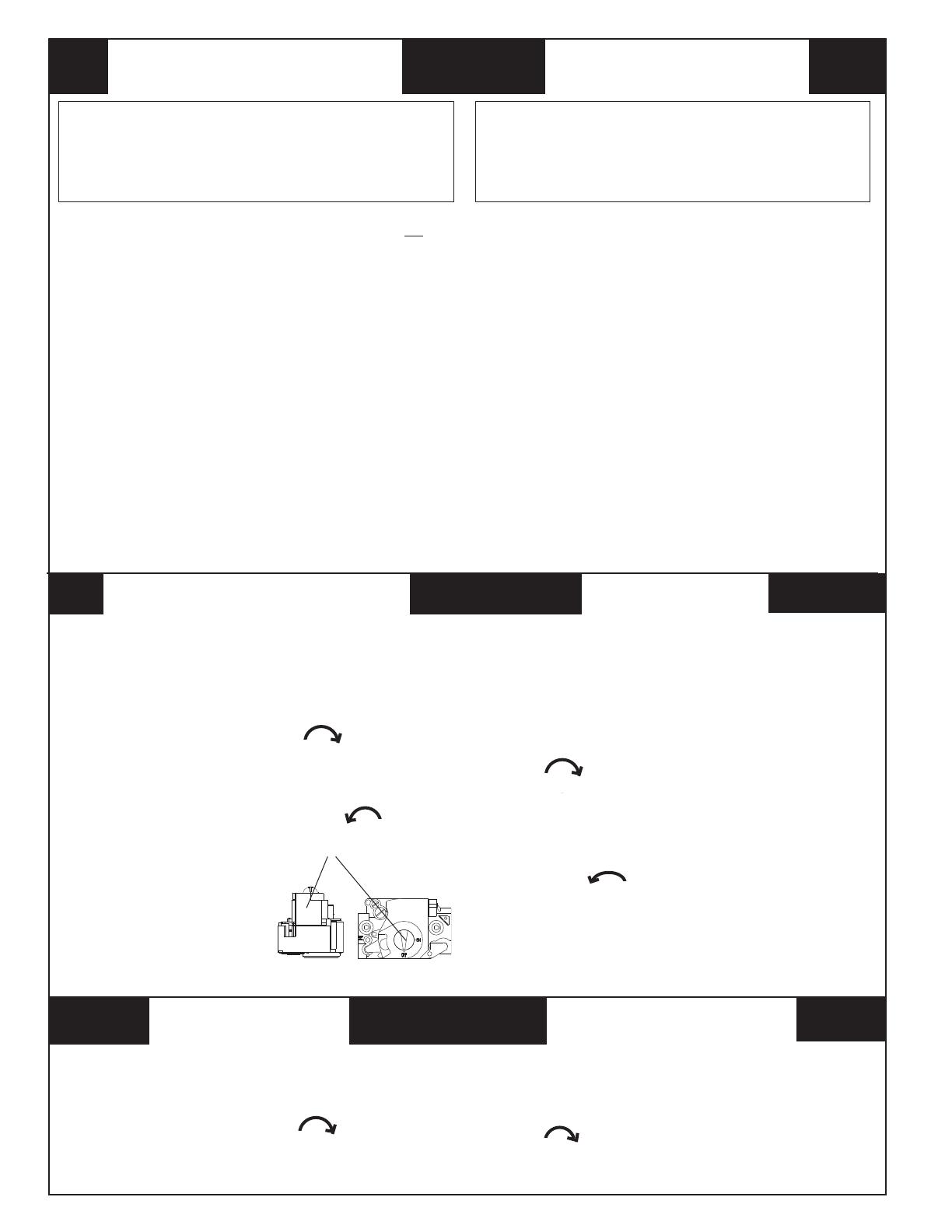
6. Move the gas control knob clockwise to “OFF”.
(See Figure 11)
7. Wait fi ve (5) minutes to clear out any gas. Then smell for
gas, including near the fl oor. If you smell gas, STOP! Follow “B” in
above information. If you don’t smell gas, go to the next step.
8. Move the gas control knob counterclockwise to “ON”.
WARNING: If you do not follow these
instructions exactly, a fi re or explosion may
result causing property damage, personal
injury, or loss of life.
MODE D’EMPLOI
DIRECTIVES D’ARRÊT
A. This appliance does not have a pilot. It is equipped with an
ignition device which automatically lights the burner. Do not try
to light the burner by hand.
B. BEFORE OPERATING smell all around the appliance area for
gas. Be sure to smell next to the fl oor because some gas is
heavier than air and will settle on the fl oor.
WHAT TO DO IF YOU SMELL GAS
Do not try to light any appliance.
Do not touch any electrical switch; do not use any phone in
your building.
Immediately call your gas supplier from a neighbor’s phone.
Follow the gas supplier’s instructions.
If you cannot reach your gas supplier, call the fi re department.
C. Use only your hand to push in or turn the gas control knob.
Never use tools. If the knob will not push in or move by hand,
do not try to repair it, call a qualifi ed service technician. Force
or attempted repair may result in a fi re or explosion.
D. Do not use this appliance if any part has been under water.
Immediately call a qualifi ed service technician to inspect the
appliance and to replace any part of the control system and
any gas control which has been under water.
OPERATING INSTRUCTIONS
A. Cet appareil ménager n’a pas de veilleuse. II est doté d’un
système d’allumage automatique. Ne pas essayer d’allumer le
brûleur manuellement.
B. AVANT L’USAGE. Attention à une possible odeur de gaz
surtout au niveau du plancher où les gaz les plus lourds ont la
tendance de se concentrer.
EN CAS D’ODEUR DE GAZ.
Ne mettre en marche aucun appareil électrique.
Ne toucher à aucun commutateur électrique, ne pas employer le
téléphone.
Quitter le bâtiment immédiatement et avertir la compagnie du
gaz en utili sant le téléphone d’un voisin.
A défaut de la compagnie du gaz, avertir le service des
pompiers.
C. Enfoncer ou faire tourner le robinet à gaz à la main seulement. Ne
jamais utiliser d’outils. S’il n’est pas possible de faire tourner ou
d’enfoncer le robinet à la main, ne pas essayer de le réparer. Faire
appel à un spécialiste. Forcer ou tenter de réparer le robinet
pourrait être à l’origine d’une explosion ou d’un incendie.
D. II est déconseillé d’utiliser cet appareil en contact prolongé avec
l’eau. Faire inspecter ou remplacer toute commande par un
technicien qualifi é si un des systèmes de contrôle du gaz s’est
trouvé sous l’eau.
ATTENTION! L’inobservation de ces
instructions peut entraîner un incendie ou une
explosion pouvant causer des dam mages à
votre propriété à votre personne, ou la mort.
POUR VOTRE SÉCURITÉ.
À LIRE AVANT L’EMPLOI
FOR YOUR SAFETY
READ BEFORE OPERATING
TO TURN OFF
GAS TO APPLIANCE
Figure 11
KNOB
(ROBINET)
1. ATTENTION! Lire d’abord la liste des mesures de sécurité ci-
dessus.
2. Mettre le thermostat à la position minimale.
3. Couper le courant électrique qui mène à l’appareil.
4. Cet appareil ménager étant doté d’un système d’allumage
automatique, ne pas essayer d’allumer le brûleur manuellement.
5. Retirer le panneau/volet d’accès de commande (panneau
supérieur s’il s’agit d’un modèle à deux panneaux).
6. Faire tourner le robinet à gaz dans le sens des aiguilles d’une
montre pour l’amener sur la position OFF (Arrêt) (Voir
Figure 11).
7. Attendre cinq (5) minutes pour s’assurer de la dissipation du gaz
En cas d’odeur, ARRÊTER LE PROCÉDÉ. Suivre les instruc-
tions ci-dessus (Section B). En l’absence de toute odeur de
gaz, avancer à l’étape suivante.
8.
Faire tourner le robinet à gaz dans le sens inverse des aiguilles
d’une montre pour l’amener sur la position ON (Marche)
(Voir Figure 11).
9. Remettre le panneau/volet d’accès de commande en place
(panneau supérieur s’il s’agit d’un modèle à deux panneaux).
10. Rebrancher l’appareil sur le réseau électrique.
11. Ajuster le thermostat à la position désirée.
12. Si l’appareil ne fonctionne pas, suivre les “Directives d’arrêt”
cidessous et appeler le technicien de service.
1. Set the thermostat to the lowest setting.
2. Turn off all electrical power to the appliance if service is to
be performed.
3. Remove the control access door/panel (upper door if two-
door model).
4. Move the gas control knob clockwise to “OFF”. Do
not use force. (See Figure 11)
5. Replace the control access door/panel (upper door if two-
door model).
1. Mettre le thermostat à la position minimale.
2. Débrancher l’appareil en prévision de la réparation.
3. Retirer le panneau/volet d’accès de commande (panneau
supérieur s’il s’agit d’un modèle à deux panneaux).
4. Faire tourner le robinet à gaz dans le sens des aiguilles d’une
montre pour l’amener sur la position OFF (Arrêt) Ne
pas forcer (Voir Figure 11).
5. Remettre le panneau/volet d’accès de commande en place
(panneau supérieur s’il s’agit d’un modèle à deux panneaux).
20
The manifold pressure for high fi re must be set to the ap-
propriate value for your installation. Refer to either Table
3 for natural gas or Table 4 for LP/propane gas to verify
the manifold pressure setting required for your particular
installation. To adjust the manifold pressure, remove the
regulator cap and turn the high fi re adjusting screw clock-
wise to increase pressure or counterclockwise to reduce
pressure. Replace the regulator cap after adjustments
are complete.
Verifying and Adjusting Temperature Rise — Verify
that the temperature rise through the unit is within the
range specifi ed on the unit data label. Temperature rises
outside the specifi ed range could result in premature heat
exchanger failure.
Place thermometers in the return and supply air stream
as close to the duct connections as possible. The
thermometer on the supply air side must be shielded from
direct radiation from the heat exchanger to avoid false
readings. Adjust all registers and duct dampers to the
desired position and run the unit for ten to fi fteen minutes
before taking any temperature readings. The temperature
rise is the difference between the supply and return air
temperatures.
For typical duct systems, the temperature rise will fall within
the range specifi ed on the data label with the blower speed
at the factory recommended setting (see Table 7). If the
temperature rise measured is outside the range specifi ed,
it may be necessary to change the blower speed. Lower
blower speeds will increase the temperature rise and higher
blower speeds will decrease the temperature rise.
The unit is equipped with a variable speed motor. Heating
and cooling speed selection is made by changing the
switch settings on the integrated control located in the unit
control box. Refer to the Variable Speed Blower Section
of this installation instruction for more details.
The VSB is designed with built in delay profi les for start
up and shut down of the system. See the Sequence of
Operation section on page 24 for more details.
TIME FOR TIME FOR
ONE REVOLUTION ONE REVOLUTION
(SECONDS) 1 5 10 (SECONDS) 1 5 10
10 360 1800 3600 66 55 273 545
12 300 1500 3000 68 53 265 529
14 257 1286 2571 70 51 257 514
16 225 1125 2250 72 50 250 500
18 200 1000 2000 74 49 243 486
20 180 900 1800 76 47 237 474
22 164 818 1636 78 46 231 462
24 150 750 1500 80 45 225 450
26 138 692 1385 82 44 220 439
28 129 643 1286 84 43 214 429
30 120 600 1200 86 42 209 419
32 113 563 1125 88 41 205 409
34 106 529 1059 90 40 200 400
36 100 500 1000 92 39 196 391
38 95 474 947 94 38 191 383
40 90 450 900 96 38 188 375
42 86 429 857 98 37 184 367
44 82 409 818 100 36 180 360
46 78 391 783 102 35 176 353
48 75 375 750 104 35 173 346
50 72 360 720 106 34 170 340
52 69 346 692 108 33 167 333
54 67 333 667 110 33 164 327
56 64 321 643 112 32 161 321
58 62 310 621 114 32 158 316
60 60 300 600 116 31 155 310
62 58 290 581 118 31 153 305
64 56 281 563 120 30 150 300
GAS FLOW RATE (CUBIC FEET PER HOUR)
CUBIC FEET PER REVOLUTION OF METER
Table 8. Gas Flow Rate (Cubic Feet Per Hour).
1 / 1

Broan DF6SF Installation guide

Category
Stoves
Type
Installation guide
This manual is also suitable for

Ask a question and I''ll find the answer in the document

Finding information in a document is now easier with AI

Ask the document