Kenmore 229960081 Owner's manual
- Category
- Water heaters & boilers
- Type
- Owner's manual

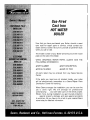
Gas-Fired
CastIron
HOTWATER
BOILER
• Installation
• Operation
• RepairParts
WARNING: Improper installation, adjustment, alteration, service or
maintenance can cause injury or property damage. Refer to this
manual. For assistance or additional information consult a qualified
installer, service agency or the gas supplier.
PRINTED IN U,S,A. FORM 608-500-1/01-56519

KENNMORE CAST IRON BOILERS
FULLONEYEARWARRANTYONHOTWATERANDGASSTEAMCASTIRONBOILERS
For one (1) year from the date of installation, when this boiler is installed and maintained in accordance
with our instructions. Sears will repair defects in material or workmanship in the boiler,free of charge.
LIMITED 12 YEAR WARRANTY ON STEAM CAST IRON BOILERS
After one (1}year and through twelve (12) years from the date of installation,Sears willfurnish a replacement
heat exchanger, ifthe heatexchanger inthe boiler isdefective. YOU PAY FOR LABOR.
LIMITED 20 YEAR WARRANTY ON HOT WATER CAST IRON BOILERS
After one (1)year and through twenty (20) yearsfrom the date of installation,Searswillfurnish a replacement
heat exchanger ifthe heatexchanger inthe boiler is defective. YOU PAYFOR LABOR.
SEARS INSTALLATION WARRANTY
In addition to any warranty extended to you on the Sears merchandise involved,which warranty becomes
effective the date the merchandise is installed,should the workmanship of any Sears arranged installation
prove faulty within one year, Sears will, upon notice from you, cause such faults to be corrected at
no additional cost to you.
FOR WARRANTY SERVICE, SIMPLY CONTACT THE NEAREST SEARS STORE OR SERVICE
CENTER THROUGHOUT THE UNITED STATES. This warranty gives you specific legal rights, and
you may also have other rights which vary from stateto state.
IMPORTANT
The following are the responsibilities of the user and are not
covered by the Warranty
1. Filter clearing or replacement.
2. Damage to unit or unsatisfactory operation due to improper
cleaning or use of unit in corrosive atmosphere.
3. Damage to unit or unsatisfactory operation due to blown fuses
or inadequate or interrupted electrical protective devices.
4. Damage to unit caused by the use of components or other
accessories not compatible with the unit.
5. ifthe unit is removedfrom the place it was originally installed,
this Warranty becomes void.
6. Damage to the unit caused by accident, abuse, negligence,
misuse, riot,fire, flood, or acts of God.
SEARSROEBUCKAND COMPANY
D/817WA
Hoffman Estates,IL60179
1. Read the Owner's Manual for Safe Operation carefully Failure
to follow the rules for safe operation and the instructions can
cause a malfunction of the boiler and result in death, serious
bodily injury,and/or property damage.
2. Check your local codes and utility requirements before
installation. The installation must be in acordance with their
directives.
3. Before servicing, allow boiler to cool. Always shut off any
electricity and gas to boiler when working on it.This will prevent
any electrical shocks or burns.
4. Never test for gas leaks with an open flame. Use soap and
check all connections. This will avoid any possibility of fire
or explosion.
5. Be certain your new boiler will be using the correct gas.
Overfiring will result in premature failure of the boiler sections
and cause dangerous operation.
6. Never vent this boiler into an enclosed space. Always vent
to the outside. Never vent to another room or inside a building.
7. Be sure there isadequate air supply for complete combustion.
8. Followa regular service and maintenance schedule forefficient
and safe operation.
2

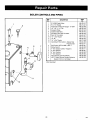
T
231/4
ASME
RELIEF VENT DAMPER
VALVE
_I ['--
-- -- --]-._._
I rV/NPT I \\ CH"
L____
d
I__
DRAIN VALVE
LEFT SIDE
TEMR/PRESS.GAUGE
!/
,_ A _, I7," SUPP_
_ -I /
iL
ROLLOLIT GAS 1
SWITCH VALVE
FRONT
AQUASTAT
1'/4" RETURN
IN]_ PILOT CONTROL
RIGHT SIDE
®
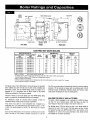
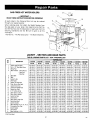
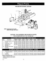
GAS-FIRED HOT WATER BOILERS
BASICBOILER UNIT N(_ NATURALGAS
NQ OF AGA HEATING
Electronic Ignition
With
Vent Damper
229.960021
229.960031
229960041
229.960051
229.960061
229,960071
229.960081
229.960091
Continuous Pilot
With
Vent Damper
229.960121
229.960131
229.960141
229.960151
229.960161
229,960171
229.960181
229.960191
SECTIONS
2
3
4
5
6
7
8
9
INPUT
*MBH
37.5
7O
105
140
175
210
245
280
CAPACITY
"MBH
3O
57
85
113
142
170
198
226
I=B=R
RATING FLUE
*MBN DIAMETER
26 4_
50 5
74 6
98 6
123 7
148 7
172 7
197 7
DIMENSIONS
NET (Inches)
,,A-
WIDTH
8
11%
14'/2
173/4
21
2474
271/2
303_
* MBH - 1,000 Stuh Btuh - British Thermal Unit Per Hour
t For aJtitudes above 2,000 ft ratings should be reduced at the rate of 4% for each 1,000 ft above sea level
Heating Capacity is based on DOE {Debarirnent of Energy) test procedure
**Add 5½" to height for Vent Damper
:_2 Section boilers are equipped with a 3" diameter flue collar on the draft diverter, and use a furnished 3'x4" increaser
fitting to install the furnished 4" vent damper
TheRatingsmarked"NetI=B=RRatings"indicatetheamountof equivalent
directradiationeachboilerwill takecareof undernormalconditionsand
thermostaticcontrol.The Net I=B=R Ratingsshownare basedon an
allowanceof 1.15 in accordancewith the factorsshownon the I=B=R
Standardaspublishedby TheHydronicsInstitute.
Selectionof boilersizeshouldbe basedupon"Net I=B=RRating"being
equaltoor greaterthanthecalculatedheatlossof thebuilding.
The manufacturershould be consultedbefore selectinga boiler for
installationshavingunusualpipingandpickuprequirements.
Theseboilersmusl standon a non-combustiblefloor•If installedon a
combustiblefloor,useCombustibleFloorBaseNumber42135-1 or 146-
14-031 (2-6 sectionboilers)or 42135-2 or 146-14-032 (7-9 section
boilers)•
TheseGas-FiredWaterBoilersarelowpressure,sectionalcastironboilers
DesignCerritifedby CSA(CanadianStandardsAssociation)for usewith
Gas.Theyareconstructedandhydrostaticallytestedfora maximumworking
pressureof 50 psi(poundspersquareinch)in accordancewithA.SM.E.
(AmericanSocietyof MechanicalEngineers)Boilerand PressureVessel
CodeSectionIVStandardsforcastironheatingboilers.
BOILERS FOR USE AT HIGH ALTITUDES
This boileris factoryequippedfor useat altitudesof 0-2,000 feetabove
sea level. For use at altitudesabove2,000 feet abovesea level, the
inputratingsarereducedbya changein mainburnerorificesize.
Foraltitudesabove2,000feet abovesea level,inputratingsshouldbe
reducedatthe rateof 4% for each1,000feet abovesealevel.Consult
the NationalFuelGasCode(NFPA54/ANS!Z223.1-1atestedition),orthe
manufacturerfor correctorifice sizing information.Highaltitudeorifices
areavailablefromtheboilermanufacturer.
3

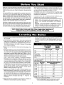
Checkto besureyouhavetherightsizeboilerbeforestartingtheinstallation.
Seeratingandcapacitytableonpreviouspage.Alsobesurethenewboileris
forthetypeofgasyouareusing.Checktheratingplateontherightsideofthe
boiler.
Youmuslseethattheboilerissuppliedwiththecorrecttypeofgas,freshair
forcombustion,andasuitableelectricalsupply.Also,theboilermustbecon-
nectedtoasuitableventingsystemandanadequatepipingsystem.Finaily,a
thermostat,properlylocated,isneededforcontroloftheheatingsystem.Ifyou
haveanydoubtsastothevariousrequirements,checkwith localauthorities
andobtainprofessionalhelpwhereneeded.Takethetimetocompleteall of
thestepsforSAFEandPROPERoperationoftheheatingsystem.
Ifthisboilerisinstalledinabuildingunderconstruction,specialcaremustbe
takentoinsureacleancombustionairsupplyduringtheconstructionprocess.
Airborneparticulatessuchasfromdrywalldustandfromfiberglassinsulation
canclogtheburnerportsandcauseincompletecombustionandsootfng.
Whererequiredbytheauthorityhavingjurisdiction,theinstallationmustcon-
formtoAmericanSocietyofMechanicalEngineersSafetyCodeforControls
andSafetyDevicesforAutomaticallyFiredBoilers,No.CSD-1.
Theinstallationmustconformto therequirementsof theauthorityhaving
jurisdictionor,intheabsenceofsuchrequirements,totheNationalFuelGas
Code,ANSIZ223.1-1atestrevision.
In Canada,theboilershallbe installedaccordingto CSA-B149.1and.2,
InstallationCodeforGasBurningAppliancesandEquipment.
Installers- Followlocalregulationswith respectto installationofCO
detectors.Followmaintenancerecommendationsin this instruction
manual.
Techniciens- Veuillezvousconformer_ lardgiementationenvigueur
concernantI" installationdesdetecteursd'oxydedecarbone.Suivrelos
consignesd'entretienfigurantdenslemanueldinstructioncijeint.
KEEP BOILER AREA CLEAN AND FREE FROM COMBUSTIBLE MATERIALS,
GASOLINE AND OTHER FLAMMABLE VAPORS AND LIQUIDS
1. Selectlevellocationascentralizedwithpipingsystem,andasnearchim-
ney,aspossible.
2. Placecratedboiler at selectedlocation,removecratebypulling crate
sidesfromtopandbottomboards.Combustiblefloors:Whenboileristo
beinstalledonacombustiblefloor,a SpecialBasePlatemustbeused-
146-14-031(2-6Section)or 146-14-032(7-9 Section).Thisboilermust
notbeinstalledon carpeting.
3. Boileris tobe level.Metalshimsmaybeusedunderbaselegsforfinal
leveling.
4. Additionalclearancesforservicemayexceedclearancesforfireprotec-
tion.Alwayscomplywiththeminimumfireprotectionclearancesshown
onthe boiler,An 18 inchclearanceshouldbe maintainedonanyside
wherepassageisrequiredtoaccessanothersideforcleaning,servicing,
inspectionorreplacementofanypartthatmayneedattention.An18inch
clearanceis recommendedonthecontrolsideforservicing.
Figure2 shows minimum clearancesto combustibleconstruction.
Roomsthatarelargein comparisonwiththesizeoftheboileraredefined
asroomshavinga volumeequalto or greaterthan16timesthevolume
oftheboiler.Wheretheactualceilingheightofa roomisgreaterthat8',
thevolumeofaroomshallbefiguredonthebasisofaceilingheightof
8'.Determinationofroomsizeshouldbebasedonthetotalvolumeofall
gasfiredequipmentinstalledin theroom.Consultsection6.3.1ofthe
NationalFuelGas Codefor further information,includingapproved
methodsfor reducingclearancesin largerooms.
5. Equipmentshallbeinstalledina locationin whichthefacilitiesforven-
tilationpermitsatisfactorycombustionofgas,properventing,andmain-
tenanceofambienttemperatureatsafelimitsundernormalconditionsof
use.Equipmentshallbelocatedsoasnottointerferewithpropercircu-
lationofair.Whennormalinfiltrationdoesnotprovidethenecessaryair,
outside air shall be introduced (See Page 4 - "Fresh Air for
Combustion"),
6. Adviseownerto keepair passagesfreeofobstructions.Ventilatingand
combustionair mustenterboilerroomwithoutrestrictions.
7. Theboilershallbeinstalledsuchthattheautomaticgasignitionsystem
componentsareprotectedfromwater(dripping,spraying,rain,etc.)dur-
ing applianceoperationandservice(condensatetrap,controlreplace-
ment,etc.).
Top
Rear
Control Side
Opposite Side
Front
Flue/Vent Connector
Near Boiler Piping
Alcove,orRoomNot
LargeInComparison
WithBoiler
2-5 SECT` 6-9 SECT,
6' 6'
6' 6"
8" 24"
6" 24"
18" 18'
6" 6"
1" 1'
BoilerVolume
BoilerSize (Cu.Ft,)
2 sect. 3.8
3 sect, 54
4 sect, 7.0
5 sect. 85
6 sect. 10.1
7 sect. 11.7
8 sect, !3.2
9 sect. 14.8
* FOR ROOMWITHSINGLEBOILERONLY
RoomLarge
InCompedsoo
WithBoiler
2-9 SECT,
6'
6'
6'
6'
18'
6'
1'
MinimumRoomVolumeRequiredToBe
LargeRoom(Cu.Ft.)*
61.6
86.6
111.6
136.6
161.7
186.7
211.7
2367
THIS UNIT MUST BE SET ON A CONCRETE OR OTHER
NON-COMBUSTIBLE MATERIAL BASE OR FLOOR.
4 70{)032

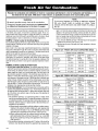
Provisionfor combustionand ventilation air must be in accordance with Section 5.3, Air for Combustionand Ventilation, of
the National Fuel Gas Code, ANSI Z223.1-1atest revision, or applicable provisionsof the local building codes.
WARNING
Be sure to provide enough fresh air for combustion.
Enough air insures proper combustion and assures that
no hazard will develop due to the lack of oxygen.
NOTE
If you use a fireplace or a kitchen or bathroom exhaust
fan, you should install an outside air intake. These
devices will rob the boiler and water heater of combus-
tion air.
Youmustprovideforenoughfreshairtoassurepropercombustion.Thefire
in theboilerusesoxygen,it musthavea continuoussupply.Theair in a
housecontainsonlyenoughoxygentosupplytheburnerfora shorttime.
Outsideair mustenterthehouseto replacethatusedbytheburner.Study
followingexamples1and2 todetermineyourfreshair requirements.
EXAMPLE1: BoilerLocatedin UnconfinedSpace
An unconfinedspaceis definedasa spacewhosevolumeis notlessthan
50cubicfeetper!,000 Btuperhourofthetotalinputratingofall appliances
installedinthatspace.
Ifyourboileris inan openarea(unpartitionedbasement)inaconventional
house,theairthatleaksthroughthecracksarounddoorsandwindowswill
usuallybeadequateto provideairforcombustion.Thedoorsshouldnotfit
tightly.Donotcaulkthecracksaroundthewindows.
Equipmentlocatedinbuildingsofunusuallytightconstructionshallbepro-
videdwithair forcombustion,ventilation,anddiMion offluegasesusing
themethodsdescribedin example2Bor shallbespeciallyengineered.The
authorityhavingjurisdictionmustapprovespeciallyengineeredinstalla-
tions.
EXAMPLE2: BoilerLocatedin ConfinedSpace
A.All Air from Inside the Building:Theconfinedspaceshallbepro-
videdwithtwopermanentopeningscommunicatingdirectlywithanaddi-
tionalroom(s)of sufficientvolumeso thatthecombinedvolumeofall
spacesmeetsthecriteriafor anunconfinedspace.Thetotalinputofall
gasutilizationequipmentinstalledin thecombinedspaceshallbecon-
sideredin makingthis determination.Eachopeningshallhavea mini-
mumfreeareaofonesquareinchper1,000Btuperhourofthetotalinput
ratingol all gasutilizationequipmentin theconfinedspace,butnotless
that100squareinches.Oneopeningshallbewithin12inchesofthetop
andonewithin12 inchesof thebottomoftheenclosure.Theminimum
dimensionofairopeningsshallnotbelessthan3 inches.
B,All Airfrom Outdoors:Theconfinedspaceshallcommunicatewiththe
outdoorsin accordancewithmethods1or 2.Theminimumdimensionof
air openingsshallnotbelessthan3 in.Whereductsareused,theyshall
beofthesamecross-sectionalareaasthefreeareaof theopeningsto
whichtheyconnect.
1.Twopermanentopenings,one commencingwithin 12 inchesofthe
top,andonecommencingwithin12inchesolthebottom,oftheenclo-
sureshallbeprovided.Theopeningsshallcommunicatedirectly,or by
theducts,withtheoutdoorsor spaces(crawlor attic)thatfreelycom-
municatewith theoutdoors,
a)Wheredirectlycommunicatingwiththeoutdoorsor wherecommu-
nicatingto theoutdoorsthroughverticalducts,eachopeningshall
haveaminimumfreeareaof1 sq.in.per4000Btuperhouroftotal
inputratingofagequipmentin theenclosure.(SeeFigure3A.)
b)Wherecommunicatingwiththeoutdoorsthroughhorizontalducts,
eachopeningshallhavea minimumfreeareaof1 sq, in.per2000
Btuperhouroftotalinputratingol all equipmentin theenclosure.
(SeeFigure3B.)
2. Onepermanentopeningcommencingwith 12inchesofthetopof the
enclosure,shallbepermittedwheretheequipmenthasclearanceofat
least1 inchfromthesidesandbackand6 inchesfromthefrontofthe
appliance,Theopeningshaddirectlycommunicatewith theoutdoors
or shallcommunicatethrougha verticalor horizontalducttotheout-
doorsorspaces(crawlor attic)thatfreelycommunicatewiththeout-
doors,andshallhaveaminimumfreeareaof:
a)1 sq,inchper3000Btuperhourofthetotalinpulol all equipment
locatedintheenclosure(SeeFigure4),and
b)Notlessthanthesumoftheareasofall venlconnectorsin thecon-
finedspace.
I Figure 3A - FRESH AIR DUCT CAPACITIES (Btuh)
1 Square Inch per 4,000 Btuh
100% Free 75% Free 25% Free
Area Area Area
Fresh Air 1/4"Wire Metal Wood
Duct Size Mesh Louvers Louvers
3" x 12" 144,000 108,000 36,000
8" x 8" 256,000 192,000 64,000
8" x 12" 384,000 288,000 96,000
81/2"x 16" 512,000 384,000 128,000
I Figure 3B - FRESH AIR DUCT CAPACITIES (Btuh)
1 Square Inchper 2,000 Btuh
100% Free 75% Free 25% Free
Area Area Area
Fresh Air 1/4"Wire Metal Wood
Duct Size Mesh Louvers Louvers
3" x 12" 72,000 54,000 18,000
8" x 8" 128,000 96,000 32,000
8" x 12" 192,000 144,000 48,000
81/2"x 16" 256,000 192,000 64,000
I Figure 4 - FRESH AiR DUCT CAPACITIES (Btuh)
1 Square Inch per 3,000 6tuh
100% Free 75% Free 25% Free
Area Area Area
Fresh Air %" Wire Metal Wood
Duct Size Mesh Louvers Louvers
3" x !2" 108,000 81,000 27,000
8" x 8" 192,000 144,000 48,000
8" x 12" 288,000 216,000 72,000
81/2"x 16" 384,000 288,000 96,000
7,_4 5

1.Placeboilerinlhe selectedlocation(asnearchimneyaspossible.)Your
boilerisshippedassembled.YouneedonlytoinstallIheBeliefValveand
a drainlinetocarryanywateror steamtoadrain.
2. InstallRebelValveintothe3/+,,pipeonthetopoftheboiler.SeeFigure5.
Use3/4"Pipeandanelbow(notfurnished)tocarrythewaterorsteamto
a nearbydrain.Donotconnectdirectlytoadrainbutleaveanairgap.No
shutoffofanydescriptionshallbeplacedbetweenthesafetyreliefvalve
andtheboiler,or ondischargepipesbetweensuchsafetyvalvesandthe
atmosphere.Installationol thesafetyreliefvalveshallconformto lhe
requirementsof the ANSI/ASMEBoiler and PressureVesselCode,
SectionIV.Themanufactureris notresponsibleforanywaterdamage.
InstallDrainValvein lowerleftsideof boilerasmarked.
3.ConnectSupplyandReturnLinestoboiler.Theconnectionsmayrequire
certainadditionalfittingsandparts,asshownondiagram(Figs.5and6).
4.Thisboilerisequippedwith 11/4"supplyandreturnconnectionsonboth
theleltandrightsidesoftheboiler.
Inconnectingthecoldwatersupplytothewaterinlelvalve,makesurethat
a cleanwatersupplyisavailable.Whenthewatersupplyisfroma wellor
pump,a sandstrainershouldbeinstalledatthepump.
A hotwaterboilerinstalledaboveradiationlevelmustbeequippedwitha
lowwatercutoffdevice.A periodicinspectionisnecessary,asisflushingof
floatlypedevices,permanufacturersspecificinstruction.
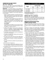
FOR USE WITH COOLING UNITS
A.Thisboiler,whenusedinconnectionwithchilledwatersystems,mustbe
installedsothatthechilledwateris pipedin parallelwiththeheating
boiler.Appropriatevalvesmustbeusedtoprevenlthechilledwaterfrom
enteringtheheatingboiler(Fig.6)_
B.Whenthis boiler is connectedto heatingcoils locatedin air handling
unitswheretheymaybeexposedto relrigeratedair circulation,thepip-
ingsystemshallbeequippedwithflowcontrolvalvesor otherautomat-
icmeanstopreventgravitycirculationoftheboilerwaterduringthecool-
ingcycle.
LOW DESIGN WATER TEMPERATURE SYSTEMS
(BELOW 140+)
If theboileristo beusedina heatingsystemwheredesignwalertempera-
luresbelow140° Faredesired(e.g.radiantfloorheating),a3-wayor4-way
mixingvalveor suitablealternativeis requiredto preventlowtemperature
returnwaterfromenteringtheboiler.Followthemixingvalvemanufacturer's
installationinstructions.
Theminimumdesignreturnwatertemperaturetotheboilertopreventcon-
densationin theboilerandventingis 120° E Theminimumhighlimit set-
tingis140° E
I CAUTION
THE ISOLATION BALL VALVES CONTAIN TEFLON
SEATS AND SEALS. OVERHEATING THIS VALVE
MAY CAUSE PREMATURE FAILURE.
COLD WATER INLET --
RELLEFJ[
VALVES A & B
OPEN FOR HEATING;
CLOSE FOR COOLING
VALVES C & D
CLOSE FOR HEATING:
OPEN FOR COOLING
TO SYSTEM
CHILLER
IDA
For boilers for connection to gas vents or chimneys, vent installations shall be
in accordance with Part 7, Venting of Equipment, of the National Fuel Gas Code,
ANSI Z223.1-1atest revision and applicable provisions of the local building codes.
CHECK YOUR CHIMNEY
This is a very importantpart of your heatingsystem.It mustbe clean,
the rightsize,properlyconstructedandin GOODCONDITION.Noboiler
canfunctionproperlywith a bad chimney.Fig. 7 givestypicalchimney
sizes.Fig.8 givesyouanideahowa boilermightbe ventedtoa chimney.
Notethattheheight(HT)is measuredfromtheventpipetothetop.
CHIMNEY SIZING
Chimneysizing, and all otheraspectsof the vent installationmustbe
in accordancewith Part7 of the NationalFuelGasCode,ANSIZ223.1
- latestrevision,andapplicableprovisionsofthelocalbuildingcodes.
In Canada,follow CAN/CGAB149.1andB149.2,InstallationCodesfor
GasBurningAppliancesandEquipment.

CONNECTING THE VENT DAMPER
AND VENT CONNECTOR
Refer to Fig. 1 flue diagram for the size and location of the
vent (flue opening). Use a 28 gauge (minimum) galvanized
pipe to connect to the chimney
IMPORTANT - The damper blade on the furnished vent
damper has a V2square inch hole (approximately 3/4"diame-
ter). On boilers equipped with standing pilot, the hole must
be teft open. On boilers equipped with intermittent ignition,
the hole should be plugged by using the plug supplied with
the vent damper.
1. Position furnished vent damper on top of flue outlet collar.
Fasten damper securely to flue outlet collar with sheet
metal screws. Make sure damper blade has clearance
to operate inside of diverter.
On 2 section boilers equipped with vent damper, the
supplied 4-inch vent damper is equipped with a 3- to
4-inch adapter so that the 4-inch vent damper may be
installed on the boiler's 3-inch flue outlet collar Fasten
all fittings securely
As An Option
The damper may be installed in any horizontal or vertical
position, closer to the flue outlet collar preferred. Follow
the diagrams - Figures 9, 10 and 11.
2. Install the vent damper to service only the single boiler
for which it is intended. The damper position indicator
shall be in a visible location following installation. Locate
the damper so that it is accessible for servicing.
3. The damper must be in the open position when appliance
main burners are operating.
4, The boiler is equipped with a factory wired harness that
plugs into the vent damper.
5. Vent pipe must be same size as the flue outlet collar,
except 2 section boilers with vent damper as noted above.
6. Slope pipe up from boiler to chimney not less than 1/4"
per foot.
7. Run pipe as directly as possible with as few elbows as
possible.
8. Do not connect to fireplace flue.
9. End of vent pipe must be flush with inside face of chimney
flue. Use a sealed-in thimble for the chimney connection.
10. Horizontal run should not be longer than 3/4the chimney
height (HT) (Fig. 8).
The sections of vent pipe should be fastened with sheet metal
screws to make the piping rigid. Horizontal portions of the
vent system must be supported to prevent sagging. Use
stovepipe wires every 5' to support the pipe from above.
If the vent pipe must go through a crawl space, double wall
vent pipe should be used. Where vent pipe passes through
a combustible wall or partition, use aventilated metal thimble.
The thimble should be 4 inches larger in diameter than the
vent p_pe.
Boiler Input
Btuh
Up to 100,000
Up to 155,000
Up to 230,000
Up to 350,000
*HT.
10-15 Ft.
6x6
6x7
7x8
9x9
FLUE AREA IN INCHES
*HT.
15-25 Ft.
6x5
6x6
7x7
8x9
*HT,
25 Ft. Up
5x5
6x5
6x7
8x8
*HT - top of thimble to fop of flue See Fig 8
For boiler input refer to table, page 2.
For information only - not meant to imply mm_rnurn sizes
MINIMUM VENT PiPE CLEARANCE
Wood and other combustible materials must not be closer
than 6' from any surface of single wall metal vent pipe. Listed
Type B vent pipe or other listed venting systems shall be
installed in accordance with their listing.
REMOVING EXISTING BOILER FROM
COMMON VENTING SYSTEM
When an existing boiler is removed from a common venting
system, the common venting system is likely to be too large
for proper venting of the appliances remaining connected
to it.
At the time of removal of an existing boiler, the following
steps shall be followed with each appliance remaining
connected to the common venting system placed in operation,
while the other appliances remaining connected to the
common venting system are not in operation.
1. Seal any unused openings in the common venting system.
2. Visually inspect the venting system for proper size and
horizontal pitch and determine there is no blockage or
restriction, leakage, corrosion and other deficiencies which
could cause an unsafe condition.
3. Insofar as ispractical, close all building doors and windows
and all doors between the space in which the appliances
remaining connected to the common venting system are
located and other spaces of the building. Turn on clothes
dryers and any appliance not connected to the common
venting system. Turn on any exhaust fans, such as range
hoods and bathroom exhausts, so they will operate at
maximum speed. Do not operate a summer exhaust fan.
Close fireplace dampers.
4. Place in operation the appliance being inspected. Follow
the lighting instructions. Adjust thermostat so appliance
will operate continuously.
5, Test for spillage at the draft hood relief opening after 5
minutes of main burner operation. Use the flame ofa match
or candle, or smoke from a cigarette, cigar or pipe.
6. After it has been determined that each appliance remain-
ing connected to the common venting system properly
vents when tested as outlined above, return doors,
windows, exhaust fans, fireplace dampers and any other
gas-burning appliance to their previous conditions of use.
_._ 7

7.Any_mproperoperationofthecommonventingsystem
shouldbecorrectedsotheinstallationconformswiththe
NationalFuelGasCode,ANSIZ2231-latestrevisionWhen
resizinganyportionofthecommonventingsystem,the
commonventingsystemshouldberesizedto approach
theminimumsizeasdeterminedusingtheappropriate
tablesin Part11 in theNationalFuelGasCode,ANSI
Z223.1-latestrevision.
For boilers for connection to gas vents or chimneys,
vent installations shall be in accordance with Part 7,
Venting of Equipment, of the National Fuel Gas Code,
ANSI Z223.1-1atest revision and applicable provisions
of the local building codes.
Vent connectors serving appliances vented by natural
draft shall not be connected into any portion of
mechanical draft systems operating under positive
pressure,
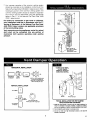
ROOF
RIDGE
3/4 HT MAXIMUM
HT
MUSTSLOPEUP
AT LEAST 1/41NCH
PER FOOT OF
HORIZONTAL RUN
HORIZONTAL INSTALLATION
TO FURNACE VENT TO CHIMNEY
OR BOILER DAMPER INSTALL VENT DAMPER WITH
ACTUATOR TO SIDES OF
VENT ONLY. DO NOT MOUNT
ABOVE OR BELOW VENT.
VERTICAL INSTALLATION
TO CHIMNEY
'6 ©
FLOW VENT
DAMPER
ACTUATOR MAY BE
TO FURNACE N INSTALLED IN ANY POSITION
OR BOILER
U
CAUTION: DO NOT INSTALL
THE VENT DAMPER
WmHIN 6 in. (152 ram) OF
COMBUSTIBLE MATERIAL
3HIMNEY
BOILER WATER HEATER
TYPICAL INSTALLATION FOR VENT DAMPER
NOTE CAUTION AND Foo'rNOTES
1. Installthe vent damper to ser,Ace only the single appliance for
which it is intended,if improperlyinstalled, a hazardous condition,
such as an explosion or carbon monoxide poisoning,could result.
2. Do not install _e vent damper on vent pipe curve.
3, Do not run wires near high temperature surfaces. Use stand-off
brackets if necessary
7o0o_

For safe, efficient operation, the vent damper and all flue
product carrying areas of the appliance must be checked
annually by you, with particular attention given to deterioration
from corrosion or other sources. If you see corrosion or other
deterioration, contact your heating contractor for repairs.
Check vent damper operation as follows:
1. When the boiler is off, check that the vent damper position
indicator points to the closed position, Fig. 11.
2. Turn the thermostat or controller up to call for heat and
check that the vent damper indicator points to the open
position, Fig. 11.
3. Turn the thermostat or controller down again and check
that the vent damper position indicator returns to the closed
position.
MANUAL OPERATION OF THE VENT DAMPER
The Effikal vent damper may be placed in the open position
to permit burner operation by using the "HOLD DAMPER
OPEN" switch, located on the damper controller. The
thermostat will control the burner firing as before, while the
damper will remain open. DO NOT turn damper open manu-
ally or motor damage will result. Set switch to "AUTOMATIC
OPERATION" to close vent damper during burner off cycle.
Forfurther information, and for a vent damper troubleshooting
guide, refer to the Effikal manual that was packaged with
the vent damper.
The vent damper must be inspected at least once a
year by a trained, experienced service technician. The
name of the person who originally installed your vent
damper is shown on the installation label.
DAMPER CLOSED DAMPER OPEN
SHOWING OPEN AND CLOSED POSITION

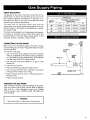
CHECK GAS SUPPLY
The gas pipe to your boiler must be the correct size for the
length of the run and for the total Btu per hour input of all
gas utilization equipment connected to it. See Fig. 12 for
the proper size. Be sure your gas line complies with local
codes and gas company requirements.
The boiler and its individual shutoff valve must be
disconnected from the gas supply piping system during any
pressure testing of that system at test pressures in excess
of V2psig (3.5 kPa).
The boiler must be isolated from the gas supply piping system
by closing its individual manual shutoff valve during any
pressure testing of the gas supply piping system at test
pressures equal to or less than V2psig (3.5 kPa).
CONNECTING THEGASPIPING
Refer to Fig. 13 for the general layout at the boiler. It shows
the basic fittings you will need. The gas line enters the boiler
from the right side.
The following rules apply:
1. Use only those piping materials and joining methods
listed as acceptable by the authority having jurisdiction,
or in the absence of such requirements, by the National
Fuel Gas Code, ANSI Z223.1-latest revision.
2. Use pipe joint compound suitable for LP gas on male
threads only.
3. Use ground joint unions.
4. Install a sediment trap upstream of gas controls,
5. Use two pipe wrenches when making the connection
to the gas valve to keep itfrom turning.
6. Install a manual shut-off valve in vertical pipe about 5
feet above floor.
7. Tighten all joints securely
NATURAL GAS
Pipe Capacity - BTU Per Hour Input
Length of Includes Fittings
Pipe - Ft.
112" 3/4" 1" 111+"
20 92,000 190,000 350,000 625,000
40 63,000 130,000 245,000 445,000
60 50,000 105,000 195,000 365,000
The length of pipe or tubing should be measured from the gas meter
MANUAL
SHUT'OFF
VALVE
AUTOMATIC
GAS
VALVE
GROUND
JOINT
MANIFOLD UNION
FLOOR
LINE
SEDIMENT TRAP
CHECKING THE GAS PIPING
Upon completion of piping, check immediately for gas leaks.
Open the manual shut-off valve. Test for leaks by applying
soap suds (or a liquid detergent) to each joint. Bubbles
forming indicate a leak. CORRECT EVEN THE SMALLEST
LEAK ATONCE.
I
WARNING
Never use a match or open flame to test for leaks.
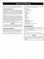
0 _I]A

All electrical work must conform to local codes as well as
the National Electrical Code, ANSI/NFPA-70, latest revision.
ELECTRIC POWER SUPPLY
Run a separate 120 volt circuit from a separate overcurrent
protective device in the electrical service entrance panel.
This should be a 15 ampere circuit. Locate a shut-off switch
at the boiler. It must be turned off during any maintenance.
Connect 120 volt power supply to aquastat terminals LI (HOT}
and L2.
The boiler, when installed, must be electrically grounded in
accordance with the requirements of the authority having
jurisdiction or, in the absence of such requirements, with the
National Electrical Code, ANSI/NFPA No. 70-latest revision.
Run a 14 gauge or heavier copper wire from the boiler to
a grounded connection in the service panel or a properly
driven and electrically grounded ground rod.
I
WARNING
Turn off electric power at fuse box before making any
line voltage connections. Follow local electrical codes.
I
INSTALL YOUR THERMOSTAT
The thermostat location has an important effect on the
operation of your boiler system. BE SURE TO FOLLOW THE
INSTRUCTIONS INCLUDED WITH YOUR THERMOSTAT.
Locate the thermostat about five feet above the floor on an
inside wall. It may be mounted directly on the wall or on
a vertically mounted outlet box. Itshould be sensing average
room temperature, so avoid the following:
DEAD SPOTS:
Behind doors
Corners and alcoves
HOT SPOTS:
Concealed pipes
Fireplace
TV sets
Radios
Lamps
Direct sunlight
Kitchens
COLD SPOTS:
Concealed pipes or ducts
Stairwells - drafts
Doors - drafts
Unheated rooms on other side of wall
Set heat anticipator at .2 amps.
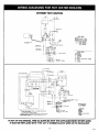
VENT DAMPER WIRING
The boiler is equipped with a factory wired harness with 4
pin molex plug, that plugs into a 4 pin molex receptacle
inside the vent damper operator.
The vent damper must be connected for the boiler to
operate.
Wiring diagrams follow for the various different models.
CAUTION
Label all wires prior to disconnection when servicing
controls. Wiring errors can cause improper and
dangerous operation. Verify proper operation after
servicing.
..... 11

INTERMITTENT IGNITION
I-"_Z • L8148E
I //--AQUASTAT
r L
W_RE COOE
FJ:x"?;_':IT'P':_IDAMPER CABLE
l_:z_ ICNIT}ON CABLE
--LINE VOLTAGE
--LOW VOLTAGE
-- --LOW VOLTAGE
FIELD WIRING
COLOR COOE
BK-BLACK
BR-BROWN
O -ORANGE
Y -YELLOW
R -RED
BT-BLACK WITH WHITE TRAX_ER
W -WHITE
B -GREEN
_i? r? _?;........
LelIK _,r
_,: il F"_ I..............
I i\_-,'_ LF--;_!! i !_-°'! _ / ,,_-
i IiiIi!T ?il II
t .1.o I _-_=111 i I!! i !
"° _ _ "°l _ I : "_-_ T I I,':',__: : [ ==="='_,_'_
Br-B_ W_ V_ TR_FR
IF ANY OF THE ORIGINAL WIRE AS SUPPLIED WITH THIS APPLIANCE MUST BE REPLACED,
IT MUST BE REPLACED WITH TYPE 105° C THERMOPLASTIC WIRE OR ITS EQUIVALENT,
1_ 70011A

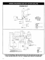
STANDING PILOT
WIRE CODE
F_';'Pr_DAMPER CABLE
C_=:zzZ_ICNITrON CABLE
--LINE VOLTAGE
--LOW VOLTAGE
-- --LOW VOLTAGE
FIELO WIRING
COLOR CODE
BK-BLACK
BR-BROWN
0 -ORANGE
Y -YELLOW
R -RED
BT-BLACK WITH WHITE TRACER
W -WHIT[
G -GREEN
_ [ ' r ................................. •
14 ; '
, I
II !',_-' I f-:-! t_ 7_'', _ ( _J I ',
II Y -o
,,., : ,,, ,,,,-L_I@'_..__'
II I_?, ?! li, ,,_ ,,",,
.... II , ,
---,U { ..... :.... ,,
IF ANY OF THE ORIGINAL WIRE AS SUPPLIED WITH THIS APPLIANCE MUST BE REPLACED,
IT MUST BE REPLACED WITH TYPE 105 ° C THERMOPLASTIC WIRE OR ITS EQUIVALENT.

RELIEF VALVE
You must have a relief valve on your boiler. Water expands
as it is heated. If there is no place for the water to expand
into, water pressure will build up inside the boiler and system.
Should this happen, the relief valve will automatically open
at a pre-determined pressure. This wi(I relieve the strain on
the boiler and system. Run a pipe from the relief valve outlet
(pipe must be same size as outlet and the open end must
not be threaded} to an open drain, tub or sink, or other suitable
drainage point not subject to freezing. Failure to do so may
cause water damage or injury should relief valve release.
EXPANSION TANK
In a properly assembled system, the expanding water flows
into an expansion tank. This tank should be of the correct
size.
The tank is filled with air. As the water expands it compresses
the air inthe tank to form an air pressure cushion. This "spring-
like" cushion serves to maintain correct operating water
pressure regardless of water temperature. This assures a
"full measure" of water, even in the highest radiation unit
of the system. It also prevents blowing off of the relief valve.
The air in the tank in the beginning (with system filled with
cold water) is sufficient for proper operation. The tank also
serves as a trap for excess air in the system. The air would
cause gurgling in the pipes and inefficient circulation in the
radiators if left in the system.
It is possible for a tank to become "water-logged" (filled with
water). It can also become overfilled with air.This can happen
after filling the system with new water. Fittings provided on
the tank and in the line to the tank are for bleeding off excess
water or air.
When installing this tank, it is important: 1} That the tank be
higher than the boiler top. 2) That the pipe to the tank
continuously rises up to the tank (so that air can "bubble"
up to it).
DIAPHRAGM TYPE EXPANSION TANK
The diaphragm type expansion tank (EX-TROL} takes the
place of the conventional expansion tank. Carefully read the
instructions packed with your EX-TROL tank assembly
The EX-TROL tank comes to you with a 10-12 pounds per
square inch air charge. This is the same as the pressure
produced in the system by the automatic fill valve. When
the system is first filled, the EX-TROL tank will contain little
or no water.
As the water is heated its pressure increases. It expands
into the EX-TROL tank, compressing the air in the tank. This
compressed air cushion permits the water in the system to
expand as the temperature changes.
The diaphragm type tank can be mounted on the air purger
fitting or at any other convenient place in the supply or return
line.
AIR ELIMINATING FITTING (AIR PURGER)
An air purger is used to remove excess air from the system.
It is installed in the supply line. It will eliminate air from the
water before it reaches the radiators and bleed off this air.
MAIN AIR VENT FOR DOWN FLOW SYSTEMS OR
DIAPHRAGM TYPE EXPANSION TANK
Before a system is filled with water, there is air in the pipes
and radiation units. Some of it will be trapped as the system
is filled. It is possible to eliminate most of this air through
the air vents on the radiation units. A main air vent will speed
and simplify this. It should be installed on the highest point
in the supply main when all radiation is below top of boiler.
AUTOMATIC FILL VALVE
For safe, efficient operation, a hot water system must be
completely tilled with water. Adding new water, when
needed can be done manually (by use of a hand valve in
the water supply line}. This requires regular attention to the
system's needs. An automatic fill valve accomplishes this
without attention. It is installed in the supply line on hot water
boilers only The valve operates through water pressure
differentials. It does not require an electrical connection.
DRAIN VALVE
This manual valve provides a means of draining all water
from the boiler and system. It is often installed in the 3A,
tapping at the bottom of the end boiler section. Or it can
be installed in a tee where the return line enters the boiler.
WATER TEMPERATURECONTROL
The water temperature limit control in the relay is adjustable
and may be set as necessary. It may be set as low as 140°
E, or as high as 240 ° E This depends on the type and amount
of radiation involved and weather conditions.
CIRCULATING PUMP
Every forced hot-water system requires a circulating pump.
A separate pump or zone valve is required for each zone,
if you have a two or more zone system. This pump must
have the capacity to provide the circulation required by your
system. The pump is connected into the return main just
ahead of the boiler. It is also wired to the electrical system.
VENT DAMPER
This product is an automatic, motorized stack damper that
has been developed to increase the efficiency of heating
systems by reducing standby losses from the heating
apparatus and the conditioned air space. The damper closes
the chimney vent when the burner is off and fully opens
it when combustion is required.
,_,_, 14

ROLLOUT SWITCH
(FLAME ROLLOUT SAFETY SHUTOFF)
The rollout switch is a temperature-sensitive fuse link device.
It is located on the boiler base just outside the fire box. In
the event of heat exchanger flueway blockage causing flame
to roll out of the fire box, the fuse will blow, shutting down
the f!ow of gas to the main burners. The fuse does not change
in appearance when blown.
If the rollout sw!tch blows, it must be replaced with an exact
replacement. Check heat exchanger flueways for blockage
when restoring system to operating condition. Do not operate
system without a rollout switch.
SPILL SWITCH
(BLOCKED VENT SAFETY SHUTOFF)
The spill switch is a manual reset disc thermostat with a fixed
setpoint (340°F), and normally closed contacts. It is located
at the relief opening of the integral draft diverter. In the event
of chimney or venting system blockage causing products
of combustion to spill out of the relief opening, the spill switch
disc heats up and the spill switch contacts will open, shutting
down the flow of gas to the main burners by removing power
to the gas valve.
In the event that the spill switch contacts open, the reset
button on the back of the switch wilt pop up The spill switch
must be reset manually, after the switch has cooled off, by
pushing the reset button down. Check the venting system
and chimney for blockage when restoring the system to
operating condition. DO NOT operate the boiler without a
spill switch.
HOW A HOT-WATER SYSTEM OPERATES
Your entire heating system (boiler, piping and radiation units}
is filled with water. As the water in the boiler is heated, it
is pumped from the top of the boiler through the supply
main to the radiation units. The cooler water in them flows
back through the return main to the boiler. This provides
positive and rapid response to the thermostat.
FILLING SYSTEM WITH WATER
Close the air vents on all radiation units. Open the valves
to these units. Make sure the boiler and expansion tank drain
cocks are closed. The air bleed screw on the tank drain
fitting should be closed. Open the valve in the line from the
boiler to the expansion tank (see page 17 for additional
information}. Open the water inlet to your boiler and leave
it open. Start with the lowest radiation unit. Open the air
vent on this unit. When all the air has escaped and water
starts to flow from the vent, close it. Go to the next radiation
unit, and repeat this process. Repeat until you have covered
every radiation unit in the system (ending up at the highest
unit in the system}. If your units have automatic vents, this
manual venting is unnecessary but itwill speed up the proper
filling of your system.
If your system is a closed expansion tank system, you may
have an Automatic Fill Valve. You may leave it open to refill
the system automatically as needed. Check the temperature-
pressure gauge. Not the position of the hand indicating
pressure. This should be between t 0 and t5 Ibs.Any lowering
of this movable hand below 10 Ibs. will indicate loss of water
due to leakage. The automatic fill valve should compensate
for this. Instructions are packaged with the valve.
I WARNING - Never run water into a hot empty boiler. I
5 7oal,

I
WARNING: If you do not follow these instructions exactly, a fire or explosion I
may result causing property damage, personal injury or loss of life,
I
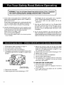
A. Some boilers are equipped with an intermittent ignition
device which automatically lights the pilot. Do not try to
light the pilot by hand.
Some boilers are equipped with a continuous pilot and
must be manually lighted. (See lighting instructions on
page 15.)A match holder is included in the parts bag.
B. BEFORE OPERATING smell all around the appliance area
for gas. Be sure to smell next to the floor because some
gas is heavier than air and will settle on the floor.
WHAT TO DO IF YOU SMELL GAS
• Do not try to light any appliance.
• Do not touch any electric switch; do not use any phone
in your building.
C,
D,
*Immediately call your gas supplier from a neighbor's
phone. Follow the gas supplier's instructions.
elf you cannot reach your gas supplier, call the fire
department.
Use only your hand to push in or turn the gas control
knob. Never use tools. If the knob will not push in or turn
by hand, don't try to repair it, call a qualified service
technician. Force or attempted repair may result in a fire
or explosion.
Do not use this appliance if any part has been under
water. Immediately call a qualified service technician to
inspect the appliance and to replace any part of the control
system and any gas control which has been under water.
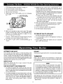
1. STOP! Read the safety information on page 14.
2. Set the thermostat to lowest setting.
3. Turn off all electric power to the appliance.
4. This appliance is equipped with an ignition
automatically lights the pilot. Do not try to
by hand.
device which
light the pilot
•AsINLET
GAS CONTROL KNOB
SHOWN IN "ON" POSITION
5. Remove lower front panel.
6. Rotate the gas control knob clockwise _I to "OFE"
7. Wait five (5) minutes to clear out any gas. Then smell
for gas, including near the floor. If you smell gas, STOP!
Follow "B" in the safety information on page 14. If you
don't smell gas, go to next step.
8. Rotatethe gascontrol knobcounterclockwise If to "ON."
9. Replace lower front panel.
10. Turn on all electric power to the appliance.
11. Set thermostat to desired setting.
12. If the appliance will not operate, follow the instructions
"To Turn Off Gas To Appliance" and call your service
technician or gas supplier.
TO TURN OFF GAS TO APPLIANCE
1. Set the thermostat to lowest setting.
2. Turn off all electric power to the appliance if service is
to be performed.
3. Push in gas control knob slightly and turn clockwise
to "OFF' Do not force.
.... 16

1. STOP! Read the safety information on page 14.
2. Set the thermostat to lowest setting.
3. Turn off all electric power to the appliance.
4. Remove lower front panel.
5. Rotate gas control knob slightly and turn clockwise
to "OFE"
_ GAS CONTROL KNOB
SHOWN IN "ON" POSITION
GAS
INLET
......i
I Ol
6)1"i
RESET BUTTON
6. Wait five (5) minutes to clear out any gas. Then smell
for gas, including near the floor. If you smell gas, STOP!
Follow "B" in the safety information on page 14. If you
don't smell gas, go to next step.
7. Find pilot - follow metal tube from gas control. The pilot
is between two burner tubes as shown in Fig. 14.
8. Turn knob on gas control counterclockwise It to
"PILOT"
9. Rotate the gas control knob counterclockwise It to
"PILOT" Push down and hold the red reset button while
you light pilot burner with a match.
After about one minute, release reset button. Pilot should
remain lit. If it goes out, turn gas control knob clockwise
to OFE To relight, repeat steps 5-9.
• If button does not pop up when released, stop and
immediately call your service technician or.gas supplier.
• If the pilot will not stay lit after several tries, turn the
gas control knob to "OFF" and call your service
technician or gas supplier.
10. After pilot remains lit when red reset button is released,
turn gas control knob counterclockwise ic to "ON."
11. Replace lower front panel.
12. Turn on all electric power to the appliance.
13. Set thermostat to desired setting.
TO TURN OFF GAS TO APPLIANCE
1. Set the thermostat to lowest setting.
2. Turn off all electric power to the appliance if service is
to be performed.
3. Push in gas control knob slightly and turn clockwise
_I to "OFE" Do not force.
AUTOMATIC GAS VALVE
The Automatic Gas Valve opens or closes according to the
heat requirements of the thermostat and temperature limit
control. It closes if the pilot goes out. Each individual control
must be operating correctly before any gas can pass to the
burners. Any one control can hold the gas supply from burner
regardless of the demand of any other control.
SAFETY PILOT
Safety Pilot prevents the flow of gas to burner if the pilot
goes out, or will not ignite.
GAS VALVE SAFETY SHUTDOWN TEST
1. For boilers equipped with continuous pilot, with main
burners firing, disconnect the thermocouple from the gas
valve. The gas valve should immediately shut off the main
burners and the pilot.
2. For boilers equipped with intermittent ignition, with main
burners firing, disconnect the ignition cable from the
intermittent pilot control box. The gas valve should shut
off the main burners. TURN OFF ELECTRIC POWER to
boiler before reconnecting ignition cable, to prevent
electric shock.
RELIGHT
Theelectricand gasshallbeofffor 5 minutesbeforerelighting.
THERMOSTAT
Keep it set at a desired room temperature. If windows are
to be opened or heat is not needed, move thermostat pointer
to a lower setting.
NOTE
In the event of failure of any component, the system
will not operate or will go into safety lockout. The system
iscompletely self-checking On every call for heat, each
component must be functioning properly to permit
operation. On safety lockout the system has to be reset
by turning the thermostat to the lowest setting for one
minute, then back to the normal setting.
Safe lighting and other performance criteria were met with
the gas manifold and control assembly provided on the boiler
when the boiler underwent tests specified in ANSI Z21.13
- latest revision.
7 _8

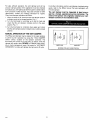
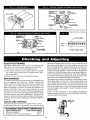
pRESSURERI_GUI._TO/I
AOJUSTMKNT
(UNC)I[ R CA/' SCRI[W
PRI_SURI_ TA
WIRING
TAr
a T| RMIF_AI._II)
IN,
€ _LOT OUTUtT
oo._
(UNr_ER CAP SCREW)
MANTEL
SHARPINNERCONES
ADJUST PILOT BURNER
Pilot flame should surround 3/8" to 1/2" of the pilot sensor.
Refer to Fig. 18. If flame needs adjusting, do it as follows:
1. Remove screw cover over pilot adjusting screw.
2. Insert small screwdriver and adjust flame as needed.
Turn screw counterclockwise to increase flame, clock-
wise to decrease.
3. Replace screw cover over pilot adjusting screw.
MAIN BURNER(S)
The main burners do not require primary air adjustment and
are not equipped with primary air shutters. Main burner
flames should form sharp blue inner cones in a softer blue
outer mantel, with no yellow. Puffs of air from blowing on the
flame or stamping on the floor will cause the flames to turn
orange momentarily. This is not unusual. Remain still when
observing the main burner flames. If the flame appearance is
not correct, check main burner orifices and the burner throat
and flame ports for dust and lint obstruction. It may be nec-
essary to remove the rollout shield to observe the main burn-
er flames. Replace rollout shield after observation. Refer to
Figure 17.
ADJUST LIMIT CONTROLS
Instructions for each control are included with the controls.
These settings can be changed after you have had some
J RECOMMENDED BOILER WATER TEMPERATURES
Type of Heating Unit Limit Control Setting
Standing Radiators .................... 180° F.
Baseboard and Convector Radiators ...... 200 ° F.
idea how the system works. Example: If your system does not
give quite enough heat in very cold weather, you can raise
the limit setting to 220° R Use the boiler gauge to check your
settings. Make the adjustments according to its readings.
Check thermostat operation. When set above temperature
indicated on the thermometer, boiler should ignite. Make cer-
tain the thermostat turns off the boiler when room tempera-
ture reaches the selected setting and starts the boiler oper-
ating when room temperature falls a few degi-ees.
After setting limit control to limit setting, check to see if it shuts
off the gas supply to the burners. Turn your thermostat up to
call for heat and let your boiler run until the temperature of the
water reaches the limit setting. The gas valve should shut off
and the circulator keep running until the thermostat is satis-
fied, or the water cools enough to restart the burners through
the limit control.
Finally, set the thermostat for the desired temperature.
Special conditions in your home and the location of the ther-
mostat will govern this setting.
3/8" to 1/2"

BURNERS
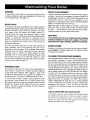
A visual check of the pilot and main burner flames should
be made at least once each year, preferably at the beginning
of the heating season. See page 18.
RELIEF VALVE
This valve should open automatically if the system pressure
exceeds the pressure rating (usually 30 psi) of the relief valve.
Should it ever fail to open under this condition, shut down
your system. Drain the system until system pressure is
reduced below the relief valve pressure rating. If valve
discharge occurs, or if valve fails to open as described above,
contact an authorized contractor or qualified service
technician to replace the relief valve and inspect the heating
system to determine the cause, as this may indicate an
equipment malfunction.
This valve should be tested every month during periods of
boiler operation, and at the beginning and end of any
extended non-service period. Prior to testing, make certain
discharge pipe is properly connected to valve outlet and
arranged so as to contain and safely dispose of boiler
discharge. Test at normal system operating pressure. Hold
the trip lever fully open for at least five seconds in order
to flush free any sediment that may lodge on the valve seat.
Then permit the valve to snap shut.
EXPANSION TANK
As previously noted, this tank may become waterlogged, or
may receive an excess of air. Frequent automatic opening
of the relief valve indicates water logging. A high boiler
temperature accompanied by unusually low radiation unit
temperature (and "knocking") indicates excess air in tank.
To correct either condition, close the valve between the boiler
and the tank. Drain the tank until it is empty Check all the
tank plugs and fittings. Tighten as necessary Open the valve
between the boiler and tank. Water will rise to the normal
height in the tank ifyou have an automatic fill valve (otherwise,
manually refill the system).
BOILER FLUE PASSAGES
Under normal operating conditions, with the burners properly
adjusted, it should not be necessary to clean the boiler flue
gas passages. However, to assure trouble-free operation, we
recommend that you have the flue passages, burner
adjustment, and operation ofthe controls checked once each
year by a competent Service Technician.
Before the start of each season (or whenever system has
been shut down for some time) recheck the whole system
for leaks.., and recheck the boiler and vent pipe for leaks.
Replace or patch any boiler seals that are faulty
VENT PIPE
The venting of this unit is very important and the piping
should be checked at least once a season. If the vent
piping shows any sign of leaking, replace it immediately.
WATER SYSTEM
If system is to remain out of service during freezing weather,
always drain It completely (water left in to freeze will crack
the pipes and/or boiler).
CLEANING YOUR BOILER AND BURNERS
Flue passages between sections should be examined yearly
and cleaned if necessary. To clean, remove burners, pilot,
and vent pipe. Remove top and front jacket panels. Remove
the two screws attaching the intermediate front panel to the
left and right side jacket panels. Remove the draft diverter
and intermediate front panel as a unit. Carefully remove the
cerafelt gasket strips. Clean passageways between sections
with a flexible handle wire brush. Remove dirt from bottom
of boiler and from between sections by vacuuming. Make
sure all flame ports in burners are open and clear. Shake
out or blow out all loose dirt in burners. Reseal seams between
adjacent sections as necessary with 400 F RTV silicone
sealant. Reassemble all parts. Be sure to check tightness
of pilot connections and condition of burner flames after
reassembly (see Figures 17 and 18). Be sure vent pipe
connections to chimney are secure and no obstructions are
present.
CIRCULATOR PUMP ISOLATION VALVES
The isolation valves in the circulator pump flanges should
be operated manually once or twice per year to prevent
the valves from becoming stuck in the open position.
Rotate the valves from the open position to the closed
position and back to the open position.

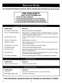
You may avoid inconvenience and service calls by checking these points before you call for service.
FOR YOUR SAFETY
WHAT TO DO IF YOU SMELL GAS
1. Do Not try to light any appliance.
2. Do not touch any electric switch, do not use the phone.
3. Leave the building immediately, then call your gas supplier.
4. If you cannot reach the gas supplier, call the fire department.
Poseibie Cause
Thermostat is not set correctly
Burner is not operating properly
No electric power to boiler
Controls out of adjustment
Radiators not heating
Circulating pump not running
Poor electrical contact
Rollout switch blown
Spill switch blown
Vent damper not operating
Possible Cause
Gas input amount is incorrect
What to do
Reset thermostat above room temperature.
Check flame. If it is yellow, the burner is not getting enough air. Or, if flame
is blue and noisy and seems to lift off the burner, the burner is getting too
much air. Contact your service technician.
Check overcurrent protection. Check to be sure electric power supply circuit
is "ON."
Reset according to instructions.
Open radiator vents to vent excess air. Check flow control valve (if used). It
may be in closed position.
Check overcurrent protection. Check relay operation.
Check all control terminals and wire joints.
Have your service technician check heat exchanger for blockage. Replace rollout
switch with exact replacement.
Have your service technician check venting system and chimney for blockage,
or down draft condition. Reset spill switch.
Consult troubleshooting guide in Effikal manual, packaged with vent damper.
What to do
Contact your service technician.
HAVE YOUR SERVICE TECHNICIAN CHECK ANY PROBLEM YOU ARE UNABLE TO CORRECT.
Page is loading ...
Page is loading ...
Page is loading ...
Page is loading ...
-
 1
1
-
 2
2
-
 3
3
-
 4
4
-
 5
5
-
 6
6
-
 7
7
-
 8
8
-
 9
9
-
 10
10
-
 11
11
-
 12
12
-
 13
13
-
 14
14
-
 15
15
-
 16
16
-
 17
17
-
 18
18
-
 19
19
-
 20
20
-
 21
21
-
 22
22
-
 23
23
-
 24
24


Kenmore 229960081 Owner's manual
- Category
- Water heaters & boilers
- Type
- Owner's manual
Ask a question and I''ll find the answer in the document
Finding information in a document is now easier with AI
Related papers
Other documents
-
 Smith Cast Iron Boilers GB200-S-3 User manual
-
Weil-McLain CG Control Supplement
-
 Ace Heating B Series Operating And Maintenance Manual
-
Dunkirk PWB IOM Installation & Operation Manual
-
Dunkirk PWX Installation & Operation Manual
-
-
 Smith Cast Iron Boilers GB100W User manual
-
Burnham 8H/8HE Operating instructions
-
-


